However, the length of the non-real-time pr2 and pr3 queues are same. â¢. DMP scheduling theme uses a multichannel. MAC protocol to send multiple packets ...
ISSN (Online) 2278-1021 ISSN (Print) 2319-5940
International Journal of Advanced Research in Computer and Communication Engineering Vol. 4, Issue 5, May 2015
Dynamic Approach for Real time and Non-Real time Packet Scheduling in WSNs. Pavithra J1, Vishwanath V Koli2, Varalakshmi B D3 M.Tech Student, Department of CS&E, Acharya Institute Of Technology, Bengaluru, India 1 M.Tech Student, Department of CS&E, Acharya Institute Of Technology, Bengaluru, India 2 Associate Professor, Department of CS&E, Acharya Institute Of Technology, Bengaluru, India 3 Abstract: Wireless sensor networks (WSNs) have a large kind of military and civil applications. Packet Scheduling is one in all the foremost essential functions of the nodes within the Wireless Sensor Networks. The sensor nodes are high-powered by batteries with restricted energy. Aggressive or enterprising environments wherever the sensor nodes are deployed or the sheared variety of the sensors prevents replacement or recharge of the batteries. So in WSNs, planning of various kinds of packets is of important energy consumptions and end-to-end task transmission delays. Most of the existing packet-scheduling mechanisms of WSN use First Come First Serve (FCFS), non-preemptive priority and preemptive priority scheduling algorithms. These algorithms deserve a high process overhead and long end-to-end task transmission delay because of improper allocation of data packets to queues in multilevel queue scheduling algorithms. Moreover, these algorithms are not dynamic to the dynamic requirements of WSN applications since their planning policies are preset. During this paper, we tend to propose a Dynamic multilevel Priority (DMP) packet scheduling scheme. Within the proposed scheme, each node, except those at the last level of the virtual hierarchy within the zone- primarily based topology of WSN, has 3 levels of priority queues. real time packets are placed into the very high priority queue and may preempt data packets in alternative queues. Non-real-time packets are placed into 2 alternative queues supported a precise threshold of their calculable time interval. Leaf nodes have 2 queues for real time and non-real-time data packets since they are doing not receive task from alternative nodes and so, reduces end-to-end delay. Keywords: Wireless Sensor networks, Priority scheduling, FCFS (FIFO), non-preemptive priority and preemptive priority, Real time and non-real time data etc. I. INTRODUCTION Wireless sensor networks encompass a bunch of sensor nodes randomly distributed during a given space as shown in Figure 1. A basic challenge of such networks lies within the energy constraint of powered sensor nodes that poses a performance limit on accomplishable network time period.
Figure 1: wireless sensor networks
The data packet delivery maintain priority and fairness with minimum latency According to the appliance, real time data packet ought to tend higher priority and non real time data packet ought to tend less priority. Many Packet scheduling algorithms square measure applied primarily to ensure packet data quality of service and transmission rate in wireless sensor networks [1]-[4] Indeed, most existing system WSN package use first come first serve (FCFS), non preemptive priority packet scheduling and preemptive priority packet scheduling. In FCFS [5] schedulers, that Copyright to IJARCCE
process data packets within the order of their time of arrival and, thus, need lots of your time to be delivered to a relevant BS (Base Station). Packet scheduling schemes are classified by the priority of data packets that area unit detected at completely different detector nodes and there's no priority for the crucial queries. In non- preemptive priority packet scheduling, the delay is more and it will ignore high priority queries. and in preemptive priority packet scheduling higher priority packets area unit processed 1st and preempt lower priority packets by saving the context of lower priority packets if they are already running in order that Interruption might occur high priority question may occur. Further-more, most existing packet scheduling algorithms of WSN area unit neither dynamic nor appropriate for big scale applications since these schedulers area unit preset and static, and can't be modified in response to a modification within the application needs or environments [6]–[8]. As an example, in several real time applications, period priority hardware is statically used and can't be modified throughout the operation of WSN applications. In this paper, we have a tendency to propose a Dynamic Multilevel Priority (DMP) packet scheduling theme for WSNs within which sensor nodes area unit nearly organized into a hierarchical data structure. Nodes that
DOI 10.17148/IJARCCE.2015.4590
409
ISSN (Online) 2278-1021 ISSN (Print) 2319-5940
International Journal of Advanced Research in Computer and Communication Engineering Vol. 4, Issue 5, May 2015
have an equivalent hop distance from the BS area unit thought-about to be situated at an equivalent gradable level. Data packets detected by nodes at completely different levels area unit processed employing a TDMA theme. As an example, nodes that an area unit situated at very cheap level and one level higher to very cheap level will be allotted timeslots one and a couple of, severally. Every node maintains 3 levels of priority queues. this can be as a result of we have a tendency to classify data packets as (I) real-time (ii) non-real-time remote data packet that area unit received from lower level nodes and (iii) non-real-time local data packets that area unit detected at the node itself . Non-real-time data packets with an equivalent priority area unit processed victimization the shortest job first (SJF) hardware theme since it's terribly economical in terms of average task waiting time. The remainder of this paper is organized as follows. In Section II, We discuss existing WSN packet scheduling algorithms. In Section III presents the premises, terminologies, working principle, pseudo-code and flow chart of the proposed DMP packet-scheduling theme. In Section IV Evaluates the performance of the DMP packet scheduling scheme. In Section v evaluates simulations and compares it against that of the prevailing FCFS and multilevel queue scheduling algorithms.
ready queue. So p2 should wait within the ready queue until the completion of the method p1. ii Preemptive: In Preemptive packet scheduling algorithm, the context of lower priority Packets is saved by processing the higher priority packets first. C. FACTOR: DATA PACKET TYPE On the basis of data packet types, packet scheduling algorithms are divided as i Real-time packet scheduling: Based on the priority and packet types, packets at the nodes should be scheduled. Among all the task packets within the queue, real time data packets are considered the very best priority packets. So the real time emergency area unit processed 1st so transmitted to the Base Station with minimum end-to-end delay. ii Non-real time packet scheduling: Non-real time task packets have lesser priority in comparison to the real time data packets. In planning of non-real time task packets either first come back first Served (FCFS) or Shortest Job first (SJF) scheduling rule will be used at the ready queue of every node.
II. LITERATURE SURVEY D. FACTOR: NUMBER OF QUEUES In this Section, numerous standard packet scheduling On the basis of number of levels of a node, packet scheduling algorithms are classified as algorithms are mentioned that supports many factors. A. FACTOR: DATA DELIVERY DEADLINE Packet scheduling algorithms area unit is classified looking on the point of the arrival of task packets to the BS (Base Station). i First Come First Served (FCFS): Most of the prevailing Wireless applications use FCFS within which the data’s area unit processed per their arrival times at the ready queue. Here, task from the distant nodes that comes later at the intermediate nodes want longer to be delivered to the BS (Base Station) however packets from the nearest nodes take less time at the intermediate nodes. In FCFS, most of the packets observe longer waiting time.
i Single-Queue: Every node features a ready queue. Data packets of all the kinds reach the ready queue and are scheduled on the premise of size, type, priority, etc., this sort of scheduling has high starvation rate. ii Multi-level Queue: A node has 2 or additional queues. Packets square measure unbroken within the queues supported their varieties and priorities. The ready queue gets separated into 3 levels of priorities. Period task packets with highest priority is unbroken in First priority queue and is processed FCFS. Non-real time data packets square measure place into the lower second and third priority levels and processed victimization completely different scheduling algorithms. Data packets square measure regular in every queue or among completely different queues. A node at bottom level has lesser variety of queues whereas a node at the upper level has several queues so as to attenuate the end-to-end transmission delay and maintain energy consumption within the network.
ii Earliest Deadline First (EDF): Whenever there square measure a lot of data packets available at the ready queue and each packets have a deadline inside that it should be transmitted to BS, the packet that has the earliest deadline is transmitted 1st. this can be considered as efficient algorithmic rule in terms of end-to-end delay and average In the analysis work the energy consumption drawback in packet waiting time. Wireless Networks has attracted world-wide. Several works [9-11] has been finished a vision of minimizing the B. FACTOR: DATA PRIORITY Packet Scheduling algorithms are classified according to energy consumption on the wake-up mode in wireless systems. A period of time design for large-scale networks the priority of data packets. [12] was planned wherever priority primarily based i Non-Preemptive: In Non-preemptive packet Scheduling computer hardware is employed. The task packets that algorithm, once a packet P1 starts process, method p1 travel most distance from the supply node to SB and have carries on even if a higher priority packet p2 arrives at the the minimum point in time are prioritized. A packet scheduling theme and formula known as event [13] for Copyright to IJARCCE
DOI 10.17148/IJARCCE.2015.4590
410
ISSN (Online) 2278-1021 ISSN (Print) 2319-5940
International Journal of Advanced Research in Computer and Communication Engineering Vol. 4, Issue 5, May 2015
period of time massive scale networks was planned. It uses Bellman-Ford formula in order to search out ways in which with less traffic and delay. Earliest point in time 1st (EDF) scheduling formula was utilized in event to transmit packets with shortest point in time. [14] Presents the largely used package of Wireless Network and differentiate them as Cooperative and preventative. Cooperative scheduling algorithms are supported by Adaptive Double Ring Scheduling (ADRS) and EDF [15] that has 2 queues with numerous priorities. Primarily based upon the point in time of the arrival packets, the computer hardware switches between the 2 queues. Cooperative schedulers are utilized in applications with restricted resources. Preventative scheduling relies on EFRM theme that is AN extension of Rate Monotonic (RM) theme. In [16], the state of distributed task aggregation in Wireless Networks is being reviewed.
level one and level 2, severally. Each zone is in addition divided into style of very little squares in such however that if a sensor nodes exists in square S1, it covers all neighbouring squares. Thus, this protocol reduces the probability of obtaining any sensing hole [17] among the network all the same the neighbouring squares of a node have not got any device node.
Routing Protocol: For the sake of energy efficiency and balance in energy consumption among sensor nodes, we tend to see using a zone-based routing protocol [4, 8]. In associate extremely zone primarily based routing protocol, each zone is understood by a zone head (ZH) and nodes follow a scheduled structure, supports the number of hops they are distant from Base station (BS). as an example, nodes in zones that unit one hop and a couple of hops distant from the academic degree unit thought of to be at
C. WORKING PRINCIPLE Scheduling data packets among several queues of a sensing element node is given in Figure 2. Data packets that are detected at a node are scheduled among type of levels among the ready queue. Then, the type of packets in each level of the ready queue is scheduled. For instance, Figure 2 demonstrates that the data packet, Data1 is scheduled to be placed among the first level, Queue1.
TDMA Scheme: Task or packet coming up with at each nodal level is performed using a TDMA theme with variable-length timeslots. Data unit transmitted from very lowest level nodes to BS through the nodes of intermediate levels. Thus, nodes at the intermediate and upper levels have extra tasks and method wants compared to lowerlevel nodes. Considering this observation, the length of timeslots at the upper-level nodes is on the point of consequent value compared with the timeslot length of lower-level nodes. On the other hand, real time and time III. PROPOSED DMP SCHEDULING SCHEME crucial emergency applications got to stop intermediate All paragraphs must be indented. All paragraphs must be nodes from aggregating data since they need to be delivered to complete users with a minimum come-at-able justified, i.e. both left-justified and right-justified. delay. Hence, for amount of your time data, the length of A. Premise timeslots at utterly totally different levels is almost equal Data traffic includes exclusively amount and non- and short. real-time data, e.g., amount health data perceived by body Fairness: This metric ensures that tasks of varied priorities sensors and non-real-time temperature data. All data packets (real-time and non-real-time) are get distributed with a minimum waiting time at the ready queue supported the priority of tasks. as an example, if of same size. associate lower priority task waits for an extended quantity Sensors are time synchronal. No data aggregation is performed at intermediate of some time for the constant arrival of higher-priority tasks, fairness defines a constraint that allows the lowernodes for real time data. Nodes are thought of located at totally different priority tasks to urge processed once a precise waiting time. levels supports the amount of hop counts from BS Timeslots are assigned to nodes at totally different levels exploitation TDMA theme, e.g., nodes at Priority: As mentioned earlier, real time and emergency the bottom level, Lk are assigned timeslot one. Details of data got to have the easiest priority. The priority of nontimeslot allocation are explained among the real-time data packets is assigned supported the sensed location (i.e., remote or local) and additionally the “Terminologies” section. The ready queue at each node has almost three dimensions of the data. The data packets that are received levels or sections for total data (pr1) non-real-time remote by node x from the lower level nodes element given higher priority than the data packets perceived at the node x itself. data (pr2) and non-real-time local data (pr3). However, if it's discovered that the lower priority non-real The length of data queues is variable. As an time native data cannot be transmitted because of the example, the length of amount data queue (pr1) is assumed continual arrival of higher priority non-real-time remote to be smaller than that of non-real-time data queues (pr2 data, they are pre-empted to allow low-priority data and pr3). However, the length of the non-real-time pr2 and packets to be processed once a precise waiting quantity. pr3 queues are same. All constant, these tasks are pre-empted by amount of your DMP scheduling theme uses a multichannel time emergency tasks. Simply just in case of two same MAC protocol to send multiple packets simultaneously priorities data packets the smaller sized data packets unit given the higher priority. B. TERMINOLOGIES
Copyright to IJARCCE
DOI 10.17148/IJARCCE.2015.4590
411
ISSN (Online) 2278-1021 ISSN (Print) 2319-5940
International Journal of Advanced Research in Computer and Communication Engineering Vol. 4, Issue 5, May 2015
Then, Data1 and Data3 of Queue1 are scheduled to be transmitted primarily based of varied criteria.
Figure 4: Proposed DMP packet scheduling scheme
D. Algorithm PSEUDO-CODE Figure 2: Scheduling data among multiple queues
Steps: Data packets that make a node area unit regular among all the degree within the ready queue. Next, data packets in every level of the queue area unit regular. Every node at different levels consists of a variable length ready queue. Pr1 queue is supposed for real time data packet, Pr2 queue is for non-real time remote data packet and Pr3 queue is for non-real time native data packet. The data packets from rock bottom level nodes traverses varied intermediate nodes and at last reaches the base station. The projected scheduling method presumes that the nodes area unit nearly organized in a very data structure. Nodes that area unit At the equal hop count from the Base station (BS) area unit thought to be placed at a similar level. Time-Division Multiplexing Access is being employed for the process of data packets at totally different levels. As an example, nodes that area unit placed at bottom level and therefore the immediate next lowest level may assign timeslots for one or pair of severally. We tend to take the biggest range of levels within the queue of a node to be 3. The motivation for choosing most 3 range of queues area unit is as follows. i. real time emergency packets with highest priority to accomplish the general aim of the Wireless Networks ii. Non-real time packets to accomplish minimum average waiting time and end-to-end delay iii. Non-real time packets with lowest priority to accomplish fairness. Shown in the figure 3 and 4
Figure 3: Block Diagram
Copyright to IJARCCE
Step 1: Node deployment. Step 2: Packet transmission starts in between neighbors. Step 3: Packet scheduling using SJF algorithm. Step 4: Design of DMP packet scheduling Queue. Step 5: take input as real time data, Non real time Remote data and Local data in the network. Step 6: Form number of levels for the network. Step 7: send data to base station. For Shortest job first Input: Sensor nodes Step 1: Calculate the distance Step 2: forward data packets to neighbour node destiny For DMP Packet scheduling Input: Source node Step 1: source node. Step 2: find priorities of data packets. Step 3: forward the packets to the queuing nodes. In our proposed DMP packet scheduling theme, nodes at very low level, lk, sense, method and transmit data throughout their allotted timeslots, whereas nodes at level lk−1 and higher levels receive data additionally to sensing, processing and transmission data. Now, we tend to gift the pseudo-code of our proposed DMP packet scheduling theme. we tend to take into account solely 2 levels within the ready queue of sensing element nodes that are set at low level since these nodes do not receive packets from any lower level nodes. Alternative nodes have 3 levels within the ready queue and place non real time native tasks into pr3 queue. We tend additionally to take into account that every node needs time to sense data packets and additionally method native and/or remote data
DOI 10.17148/IJARCCE.2015.4590
412
ISSN (Online) 2278-1021 ISSN (Print) 2319-5940
International Journal of Advanced Research in Computer and Communication Engineering Vol. 4, Issue 5, May 2015
packets. For example, t1 (k) within the pseudo-code represents the period of time data sensing time at a node. If the interval of real time data at node is a smaller amount than t1 (k) then node can have time remaining to method non-real-time pr2 data packets. Similarly, if the nodes still has some remaining time, it will process non-real-time pr3 data packets. The pseudo-code additionally shows that if the pr1 queue is empty and pr2 packets are processed α consecutive timeslots, the process of pr2 data packets are preempted for j timeslots. E. Flowchart
Figure 5. Flowchart for DMP Scheme
IV. PERFORMANCE ANALYSIS In this section, we analyse the performance of the proposed DMP task scheduling scheme in terms of end to end Delay, and total waiting time. A. End-to-End Delay In the following, we tend to formulate the typical end-toend delay of sending completely different priority data packets to the Base station (BS). Again, we tend to interchange knowledgeably use task and data to represent the data packets that area unit perceived at a detector node. Real-time Priority1 Queue Data: Let us assume that a node X, residing at level Lk is sensing a period, emergency event, e.g., fireplace detection. This node transmits the emergency priority1 data to base station through lk−1 intermediate levels. We tend to take into account the subsequent situation whereby whenever a real time data packet reaches a neighbouring active node, y at Associate in higher level, a non-real time lowers priority data is being processed that node. Hence, task delivery at y is preempted to send period real time data. While taskk, i is received by node at level k, i.e., Lk do If Type (taskk, i) = real − time then Put taskk, i into pr1 queue Else if node I is not at lowest levels then If task k, i is not local then Put task k, i into pr2 queue Else Put taskk, i into pr3 queue Copyright to IJARCCE
End if Else Put task k, i into pr2 queue End if Assume, the duration of a timeslot at Lk ← t (k) Data sensing time of node at Lk ← senseT imek (t) Remaining time after data sensing, t1 (k) = t (k) − senseT imek (t) Let total real-time tasks for node at Lk ← nk (pr1) Let procT imepr1 (k) ← Σnk (pr1) j=1 procT ime (j) If procT imepr1 (k) < t1 (k) then All pr1 tasks of node at Lk are processed as FCFS Remaining time t2 (k) ← t1 (k) − procT imepr1 (k) Let, total pr2 tasks for node at Lk ← nk (pr2) Let procT imepr2 (k) ← Σnk (pr2) j=1 procT ime (j) If procT imepr2 (k) < t2 (k) then All pr2 tasks are processed as FCFS Pr3 tasks are processed as FCFS for the remaining time, t3 (k) ← t2 (k) − procT imepr2 (k) Else Pr2 tasks are processed for t2 (k) time No pr3 tasks are processed End if Else Only pr1 tasks are processed for t1 (k) time No pr2 and pr3 tasks are processed End if If pr1 queue empty & pr2 tasks are processed α consecutive timeslots Since t (k) ≤ procT imepr2 (k) then Pr2 tasks are preempted at α + 1, . . ., α + j timeslots by pr3 tasks If pr1 task arrives during any of α+1, α+2, . . ., α+j timeslots then Pr3 tasks are preempted and pr1 tasks are processed Context are transferred again for processing pr3 tasks End if End if End while Transmission time or delay that's needs to position real time task from a node into the medium is equal to datapr1/st. The propagation time or delay to transmit task from the supply to destination is often developed as d/sp. considering the top of mentioned situation the end-to-end delay for causation real time task satisfies the subsequent difference. delaypr1≥Lk×(datapr1/st+pr1proc(t))+d/sp+(Lk×toverhead) where datapr1 denotes the period data size, st denotes the data transmission speed, d is that the distance from the supply node to BS, wherever d = ΣlkI=1 di, sp denotes the propagation speed over the wireless medium, pr1proc(t) is that the time interval of real time at every node However, a period task t1 has got to wait if there's variety, npr1, of a real time. Task prior to t1 at the pr1 queue. We have a tendency to assume that every real time task have identical size. Therefore, the end-to-end delay for a period task t1
DOI 10.17148/IJARCCE.2015.4590
413
ISSN (Online) 2278-1021 ISSN (Print) 2319-5940
International Journal of Advanced Research in Computer and Communication Engineering Vol. 4, Issue 5, May 2015
considering that t1 has npr1 variety of period tasks prior to ready queue thus that we've pr21(t) ≤ pr22(t) ≤ . . . pr2n(t). If it, pr2 tasks area unit not preempted by pr1 tasks and may be delayt1≥Σnpr1i=1(delaypr1 )i completed at intervals the t2(k) time, the common waiting time for pr2 tasks may be expressed as follows: Non-real time Priority two Queue Data: Tasks at pr2 queue are often preempted by period ones. The coordinated universal time or delay to position pr 2 task from a node into the medium are often so computed as datapr2/st. Thus, the entire end-to-end delay for a pr2 task The average waiting time of pr2 tasks is given by that may be processed within the same timeslot exceeds
Non-real time Priority three Queue Data: In the best case, once no task is on the market at the pr1 and pr2 queues, the end-to-end delay of the pr3 tasks are nearly adequate to that of the pr1 queue tasks though it will disagree slightly supported the scale of the pr3 queue task. We have a tendency to assume that the pr3 queue tasks square measure processed by preempting pr 2 queue tasks if for α consecutive timeslots there's no task at the pr1 queue however there square measure tasks obtainable at the pr2 queue. Let tk denote the length of a timeslot of nodes at level lk. The coordinated universal time or delay to position pr3 task from a node into the wireless medium is adequate to datapr3/st. However, throughout the process of the pr3 queue tasks, these tasks are often preempted by real time tasks. they're processed once more once the completion of period tasks. Thus, the end-to-end delay for processing pr3 tasks are surpassing.
B. Average waiting time In the following, we have a tendency to formulate the average waiting time of tasks at completely different workloads. Allow us to assume that priji represents the time interval of the j-th pri task at a node x, Where, 1 ≤ i ≤ 3 and 1≤ ji ≤ ni. For time period tasks, i=1 (i.e., pr1). Presumptuous that real time and emergency tasks seldom occur and need a awfully short time to urge processed, pr 1(t) < t(k). Hence, all tasks,1 ≤ j1 ≤ n1, within the pr1 queue complete process and tasks in the pr2 and pr3 queues are processed for the remaining, t2(k) = t(k) − pr1(t), amount of your time. Since pr1 tasks are processed as FCFS, the typical waiting time for time period, pr1 tasks at node x is
Where the primary pr1 task has no waiting time and waiting time for the j-th pr1 task is adequate ∑Jm=1 pr1,m(t). Now, let pr2 tasks be sorted in step with the ascending order of the processing time, pr2j2 (t), of pr2 tasks at the Copyright to IJARCCE
The above equation presents the waiting time of pr2 tasks of the nodes at higher levels and have pr1, pr2 and pr3 queues at every node. However the lowest-level nodes solely have the pr1 and pr2 so, pr2 tasks are not preempted by pr3 tasks at very lowest level. Similarly, we are able to formulate the common waiting time for Pr3(t). The average waiting time of pr3 tasks at a node. exceeds
V. PERFORMANCE EVALUATION The simulation model is implemented using the C language. It is used to evaluate the performance of the planned DMP packet scheduling theme, examination it against the FCFS, and Multilevel Queue scheduling schemes. The comparison is created in terms of end-to-end data transmission delay. The ready queue of every node will hold a most of fifty tasks. Every task contains a Type ID that identifies its type. As an example, type zero is taken into account to be a real time task. Data packets are placed into the ready queue supported the processing time of the task. Moreover, every packet contains a hop count range that's allotted every which way,
DOI 10.17148/IJARCCE.2015.4590
414
ISSN (Online) 2278-1021 ISSN (Print) 2319-5940
International Journal of Advanced Research in Computer and Communication Engineering Vol. 4, Issue 5, May 2015
and therefore the packet with the best hop count range is placed into the highest-priority queue. We have a tendency to run the simulation for a particular range of within the network till data from a node in every level reach base station. Simulation results are given for both real time data and all kinds of data traffic. Table I presents simulation parameters, and their various values. TABLE 1 Simulation parameters And their respective values
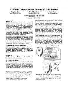
Figure 7: End-to-End delay of real time data over a number of levels
Figure 6 illustrates the end-to-end packet transmission delay of real time packets over variety levels. We have a tendency to expect that the proposed DMP scheduling theme outperforms the present FCFS, and multilevel queue scheduler. this is often as a result of the proposed scheduling theme provides the highest priority to real time tasks and additionally permits real time task packets to preempt the process of non-real time data packets. Thus, real time task packets have lower data transmission delays Figure 8: waiting time of real time data over number of levels
Figure 8 demonstrates the common waiting time of real time task over range of levels. From these results, we find that the DMP task scheduling theme outperforms FCFS, and Multilevel queue scheduler in terms of end-to-end task transmission delay. This can be as a result of within the proposed scheme, the tasks that arrive from the lower level nodes area unit given higher priority than the tasks at this node. Thus, the average task transmission delay.
Figure 6: End-to-end delay of real time data over number of zones
Figure 7 demonstrates the end-to-end delay of all kinds of data traffic over variety of levels. From these results, we discover that the DMP task scheduling theme outperforms FCFS, and Multilevel queue scheduler in terms of end-toend data transmission delay. This is often as a result of within the proposed scheme, the tasks that arrive from the lower level nodes area unit given higher priority than the tasks at the present node. Thus, the common data transmission delay is shortened.
Figure 9: Fairness over Number of Zones
The Figure 9 demonstrates the fairness of DMP comparing to the Existing FCFS and Multilevel.
Copyright to IJARCCE
DOI 10.17148/IJARCCE.2015.4590
415
ISSN (Online) 2278-1021 ISSN (Print) 2319-5940
International Journal of Advanced Research in Computer and Communication Engineering Vol. 4, Issue 5, May 2015
VI. CONCLUSION AND FUTURE SCOPE In the paper, we have got planned a dynamic multilevel priority packet scheduling algorithmic rule for wireless sensing networks considering the prioritization data packets to satisfy the goals of WSN and additionally to cut back the delay time of the packets returning from lower level nodes by giving preference to real time packets and so to data packets from lower level nodes severally. that the planned scheduling theme adapts higher to the wants that are dynamical in WSN applications and schedules the important time data packets with higher priority maintaining a minimum quantity delay from supply to destination. Dynamic structure Priority (DMP) packet scheduling theme for Wireless sensor Networks (WSNs). The theme uses three-level of priority queues to schedule data packets supported their types and priorities. It ensures minimum end-to-end data transmission for the very best priority data whereas exhibiting acceptable fairness towards lowest-priority data. Experimental results show that the proposed DMP packet scheduling theme has higher performance than the present FCFS and multilevel queue scheduling in terms of the common task waiting time and end-to-end delay.. As enhancements to the proposed DMP theme, we have a tendency to envision assignment task priority supported task deadline rather than the shortest task interval. to cut back process overhead and save task measure, we have a tendency to might conjointly think about removing tasks with expired deadlines from the medium. what is more, if a real time task holds the resources for an extended amount of your time, alternative tasks have to be compelled to stay up for associate degree vague amount time, other tasks need to wait for an undefined period of time, causing the occurrence of a deadlock. this deadlock degrades the performance of task scheduling schemes in terms of end-to- end delay. Hence, we'd cope with the circular wait and preventive conditions to stop standstill from occurring. We’d conjointly validate the simulation result employing a real test-bed.
[8] Available: http://webs.cs.berkeley.edu/tos, accessed June 2010. [9] R. Zheng, J. C. Hou, and L. Sha, “Asynchronous wakeup for ad hoc networks,” in Proc. 4th ACM Int. Symp. Mobihoc, Annapolis, MD,Jun. 2003, pp. 35–45. [10] X. Yang and N. H. Vaidya, “A wakeup scheme for sensor networks: Achieving balance between energy saving and end-to-end delay,” in Proc.IEEE 10th RTAS, Toronto, Canada, May 2004, pp. 19–26. [11] M. Peng and W. Wang, “An adaptive energy saving mechanism in the wireless packet access network,” in Proc. IEEE WCNC, Las Vegas, NV, Apr. 2008, pp. 1536–1540. [12] C. Lu, B. M. Blum, T. F. Abdelzaher, J. A. Stankovic, and T. He, “RAP: a real-time communication architecture for large-scale wireless sensor networks,” in Proc. 2002 IEEE Real-Time Embedded Technol. Appl. Symp., pp. 55–6 [13] K. Mizanian, R. Hajisheykhi, M. Baharloo, and A. H. Jahangir, “RACE: a real-time scheduling policy and communication architecture for largescale wireless sensor networks,” in Proc. 2009 Commun. Netw. Services Research Conf., pp. 458–460 [14] P. A. Levis, “TinyOS: an open operating system for wireless sensor networks (invited seminar),” in Proc. 2006 International Conf. Mobile Data Manag., p. 63. [15] K. Lin, H. Zhao, Z. Y. Yin, and Y. G. Bi, “An adaptive double ring scheduling strategy based on tinyos,” J. Northeastern University Natural Sci., vol. 28, no. 7, pp. 985– 988, 2007.. [16] Z. Ye, A. A. Abouzeid, and J. Ai, “Optimal stochastic policies for distributed data aggregation in wireless sensor networks,” IEEE/ACM Trans. Netw., vol. 17, no. 5, pp. 1494–1507, Oct. 2009. [17] L. Karim, N. Nasser, and T. El Salti, “Efficient zone-based routing protocol of sensor network in agriculture monitoring systems,” in Proc. 2011 International Conf. Commun. Inf. Technol., pp. 167–170.
REFERENCES [1] G. Anastasi, M. Conti, and M. Di Francesco, “Extending the lifetime of wireless sensor networks through adaptive sleep,” IEEE Trans. Industrial Datarmatics, vol. 5, no. 3, pp. 351–365, 2009. [2] G. Bergmann, M. Molnar, L. Gonczy, and B. Cousin, “Optimal period length for the CQS sensor network scheduling algorithm,” in Proc. 2010 International Conf. Netw. Services, pp. 192–199. 1458 IEEE TRANSACTIONS ON WIRELESS COMMUNICATIONS, VOL. 12, NO. 4, APRIL 2013 [3] E. Bulut and I. Korpeoglu, “DSSP: a dynamic sleep scheduling protocol for prolonging the lifetime of wireless sensor networks,” in Proc. 2007 International Conf. Advanced Inf. Networking Appl., vol. 2, pp. 725– 730. [4] S. Chachra and M. Marefat, “Distributed algorithms for sleep scheduling in wireless sensor networks,” in Proc. 2006 IEEE International Conf. Robot. Autom., pp. 3101–3107. [5] W. Stallings, Operating Systems, 2nd edition. Prentice Hall, [6] Y. Zhao, Q. Wang, W. Wang, D. Jiang, and Y. Liu, “Research on the priority-based soft real-time task scheduling in TinyOS,” in Proc. 2009 International Conf. Inf. Technol. Comput. Sci., vol. 1, pp. 562–565. [7] TinyOS. Available: http://webs.cs.berkeley.edu/tos, accessed June 2010. Copyright to IJARCCE
DOI 10.17148/IJARCCE.2015.4590
416