Nov 24, 2010 - AbstractâBackground updating is fundamental in mobile objects detection applications. This paper proposes a background updating method ...
The 8th France-Japan and 6th Europe-Asia Congress on Mechatronics November 22-24, 2010, Yokohama, Japan
Dynamic background modeling for moving objects detection using a mobile stereo camera Alessandro Moro, Enzo Mumolo University of Trieste Trieste, ITALY
Massimiliano Nolich IFACE s.r.l. Trieste, ITALY
Abstract—Background updating is fundamental in mobile objects detection applications. This paper proposes a background updating method with a moving stereo camera. The proposed algorithm is based on the detection of the regions in the image that have major color intensity in the scene (called light zones). From these light zones some keypoints are extracted and matched between the previous background and the current foreground images. Image registration is performed by moving the old background image according to the keypoints matching so that the foreground and background images are mostly aligned. The proposed method requires that the camera moves slowly and it is used for moving objects detection with background subtraction. Three types of keypoints are tested using the same homography: light zone, SIFT and SURF keypoints. We show experimentally that, on the average, light zone keypoints performances are equal to or better than SIFT keypoints, and are faster to compute; moreover, the SURF keypoints perform worse. To get better performances, when the light zone keypoints fail, then the SIFT keypoints are used in a data fusion framework.
I. I NTRODUCTION Moving object detection from a moving camera is fundamental in many mechatronic tasks, including autonomous and industrial robotics and transportation systems. Most of the moving objects detection schemes refer to fixed cameras. The main difference between motion detection from a fixed and a moving camera, is the creation of the background model. In this paper we deal with the problem of achieving a stable background while the camera moves. In this work, we use the following camera movements: rotations on the vertical camera axis and translations of the optical axis. The basic idea is to acquire an initial background image, and to align it to the subsequent frames. If the camera movement is slow, there are several features that can be matched between the two images. The alignment is obtained by moving each pixel of the background image according to a registration matrix computed on the basis of the correspondence between the anchor-points (in the following called keypoints) detected in the background and foreground images. The main contribution of this paper is the use of the light zones detected in the images to extract keypoints. Light zones are intrinsic features of every image and include reflecting surfaces and light emitting devices. When the light zone keypoints fail, then the SIFT keypoints are used in a data fusion framework. The proposed method have better performances
Kenji Terabayashi, Kazunori Umeda Chuo University, CREST JST Tokio, JAPAN
than using SIFT or SURF keypoints in terms of computational complexity, number of correctly matched frames and quality of alignment. It is worth noting that the light zones do not describe objects characteristics, but only the light and reflectance properties of the environment; hence, their field of application is more limited than SIFT or SURF. We will show that SIFT and light zones keypoints have similar performances in the background updating task; however the SIFT keypoints are about one order of magnitude more computationally complex than the light keypoints and SURF keypoints are simpler to compute but perform worse. The background updating algorithm described in this paper has been used in a background subtraction moving objects detection framework. This paper is structured as follows. In Section II previous work on background modeling and updating is summarized. In Section III an overview of the proposed background modeling is presented. A detailed presentation of keypoints based on light zones is reported in Section IV, and the registration and updating technique is presented in Section V. In Section VI SIFT and SURF features are briefly recalled, and their performances are compared to light zone keypoints. Finally, Section VII reports some concluding remarks. II. R ELATED WORK There are many papers dealing with background modeling, mostly related to fixed cameras and for mobile object detection. To this extent, early approaches assumed a stable background that was coupled with a simple, and known, noise process or assumed a pixel-wise statistical model that conformed to a Gaussian [1]. Although stable in controlled indoor conditions, these techniques are sensitive to global illumination changes or when local pixel variation is not modeled in the noise term. More sophisticated approaches using a multi-modal Gaussian Mixture Model (GMM), for example [2], were introduced to deal with more scene changes than previously possible. Non-parametric estimation of a probability density function (pdf) for both background and foreground was introduced by Elgammal et. al. [3] to partly alleviate this. Less papers that deal with moving cameras, as compared to fixed cameras, have been published. Notably, [4] deal with pan/tilt camera movements. The authors describe approaches for coping with inaccuracies due to motion
143
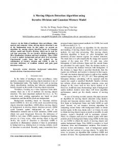
blur, mixed pixels at object boundaries, and errors in image stabilization caused by noise, small camera translations or minor errors. The background modeling problem under freemoving camera movements is treated in [5] and [6]. Both derive a dense-correspondence between pixels, but [5] models the correspondence between current frame and background model using a minimal span tree, while [6] derives a multilayer homography algorithm. Detection of motion regions in video sequences observed by a moving camera is described in [7], using a measure of the inconsistency between the projective structures from the same point under camera motion and reference plane change. In [8] is described an approach that estimates the camera motion between consecutive frames using the similarity between frames; the similarity is computed by correlating edge segments. In [9] the background model is obtained by collecting good statistics among the appearance of each 2D location. III. BACKGROUND MODELING ALGORITHM OVERVIEW The stereo camera used in this work is a Bumblebee [10] stereo camera, which is a Firewire CCD camera with a definition of 640x480 pixels at 48 fps. We consider images acquired by the stereo camera: they are combined and rectified, and for each pixel its depth is computed. As a moving camera is considered, the background image should be updated in order to take into account the viewpoint change. If the movement of the stereo camera is slow, the previous (background) and the current (foreground) images acquired by the system have a strong correlation, as the portion of the environment captured in the images is almost the same, as shown in Fig. 1.
Fig. 1.
Background (left) and foreground (right) images.
The algorithm is summarized as follows (Fig. 2). Initially,
Fig. 2.
Overview of the background update algorithm.
the system uses the first image as initial background. Then,
starting from a stereo image of the foreground, the algorithm performs the following steps: A) detection of keypoints in both foreground and background images; B) matching of keypoints between foreground and background; C) images omography using pixel position and depth; D) background update. As the algorithm provides to map the old background on the new viewpoint of the camera, a change detection algorithm (based for instance on background subtraction) can be performed. We propose to use the regions of the images that have high color intensity. The updating process based on these regions in some cases can fail, for example when the number of detected keypoints is not enough to compute the registration transform. In these cases, another set of keypoints are estimated using other approaches, i.e. SIFT. IV. L IGHT ZONE KEYPOINTS In computer vision, researchers have concentrated their attention on the detection of changes or features in order to recognize and localize objects. The use of illuminated components of images as features has not been taken into account so far. Light sources or reflecting surfaces are usually present in real images taken both in indoor and outdoor environment, and are not so wide in the image if the camera has an automatic white balance activated. Starting from these considerations, we have defined a technique suited to identify such keypoints in every image. The proposed methodology uses the color distribution histograms, that can be computed for every image, to detect keypoints: a threshold on each color component is adaptively chosen and the regions of the images that are over these thresholds (light zones), are used to estimate the points to correlate the background and the foreground images, under the assumption that the two images are taken from a camera that moves slowly. More precisely, the proposed method analyzes the color histograms of the image in order to detect the pixels belonging to light zone. The images are taken using the Bumblebee color camera as reported in Section III and are represented in the RGB color space [11]. More precisely, a pixel in the color image is considered belonging to a light zone if the intensity of each color channel Ic is greater than a threshold mc , where c represent the name of the color channel (Red, Green or Blue). The threshold mc is adaptively computed in each image, as reported in the following. Given an image A, for each channel of the image, the histogram Hc is computed: Hc represents, for every intensity value in the range [0..255], the number of pixels in the image that present that particular value of the component (Fig. 3). The histogram Hc is analyzed as follows. For each Hc , the last local maximum Mc is computed, starting from the maximum intensity down to the minimum: � ( � i i if M i − Mα ≥ Hci and Hci > σ (1) Mc = 0 otherwise where i is the histogram index in the range [0, 255] and M i is the maximum number of entries obtained since the bin i.
144
Fig. 3. RGB component histogram of a 2D color image. The vertical lines depict local minimum.
From Mc is than searched the local minimum mc as follows: � ( � i i if mi − mα ≤ Hci and Hci > σ (2) mc = 0 otherwise i
where m is the minimum number of entries obtained since the bin i. In eq. (1) and (2), α is greater that one constant value needed for reducing oscillations, and σ is the noise level. The mc thresholds are then used to create a mask M 1 which defines if a pixel is in a light zone. For each point of the image, a pixel (x, y) is considered belonging to a light zone if (IR ≥ mR ) ∧ (IG ≥ mG ) ∧ (IB ≥ mB ) is true. In Fig. 4 some examples of light zones are depicted in red. Finally, the keypoints are selected in each light zone. More precisely, adjacent pixels are grouped in connected regions using an iterative connecting graph approach on the mask M 1. Only the regions containing more than k points are used (k=5 is usually a good choice). The center of each light zone is a light zone keypoint. A. Light zone keypoints matching The light zones keypoints belonging to the foreground image (C) and the background image (C 0 ) are matched in order to perform registration. Let us call n the maximum number of points in C and C 0 , n = max(|C|, |C 0 |), and k = min(|C|, |C 0 |). There are k possible connections between background and foreground: a list of indexes, l[.], is built considering all possible groups of k indexes�in the�set of n keypoints; the number of such groups n is ln,k = . k For each keypoint, a matching score is estimated to represent the spatial relation that each keypoint has with the other keypoints of its group. The matching score is evaluated on the basis of the Euclidean distance, the Manhattan distance, the horizontal and vertical distances and the orientation distance of the point with the other points. The five distances p are estimated as follows: Pl[k] di = j=l[1] (Ci,x − Cj,x )2 + (Ci,y − Cj,y )2 , Pl[k] dMi = j=l[1] |Ci,x − Cj,x | + |Ci,y − Cj,y |, Pl[k] dHi = j=l[1] (Ci,x − Cj,x ), Pl[k] dOi = j=l[1] (Ci,y − Cj,y ),
Fig. 5. Successful (left) and unsuccessful (right) correspondence points detection with light zone detection. The unsuccessful correspondence is due to insufficient number of light zones.
Pl[k] Ci,y −Cj,y dφi = j=l[1] arctan Ci,x −Cj,x , for every region i. Each light zone keypoint of the background image is matched with each light zone keypoint of the foreground image. The matching score of each group is computed as the sum of the normalized distances. The match between the group i (from background image) and j (from foreground image) is obtained as the minimum difference of normalized distances as follows. Given � �2 dj −dmin di −dmax ∆d = dmax , −dmin − dmax −dmin �2 � dMj −dMmin dMi −dMmax − ∆dM = dM , −dMmin dMmax −dMmin � max �2 dHj −dHmin dHi −dHmax ∆dH = dH , −dHmin − dHmax −dHmin �2 � max dOj −dOmin i −dOmax , ∆dO = dOdO −dOmin − dOmax −dOmin � max �2 dφj −dφmin i −dφmax ∆dφ = dφdφ − dφmax , −dφmin max −dφmin the match is performed as � �p ∆d + ∆dM + ∆dH + ∆dO + ∆dφ . (i, j) = argmin (3) In Fig. 5, left column, we report a correspondence points example. In the top image, the background picture of an indoor environment is shown. After a camera rotation, the acquired picture is reported in the bottom of Fig. 5, left column, showing that a person moved into the scene. The keypoints detected as light zones are depicted in red. In the same environment, after a while, another image is acquired and it shown in Fig. 5, right column. In this case there are no enough light zones and other keypoints must be used. V. BACKGROUND UPDATE We use the registration method described in [12][13][14] to evaluate the registration matrix needed to perform the
145
Fig. 4.
Examples of detection of light zones in indoor and outdoor environments.
rototranslation of the background. From the matching phase, we obtain a list of keypoint pairs suitable for initial estimation of the relative pose. The light zone keypoints can be replaced by SIFT [15] keypoints if using light zones the performances are not satisfactory. The following pseudocode represents a data fusion framework that describes how the two kinds of keypoints are used together. IF
we compute the minimum of the alignment error X 2 E= [(R bi + t − fi ) · ni ]
(4)
i
with respect to the rotation R (3x3 matrix) and translation t (3x1 matrix), where the points (bi , fi ) have normals ni . B. New background
(number of light zones > thr1) THEN Use the light keypoints; IF (background updated image rotation > thr2) THEN Use the SIFT keypoints;
ELSE Use SIFT keypoints;
where thr1 is the minimum number of keypoints required for a correct registration transform (typically equal to 3), and thr2 is the maximum allowed camera rotation. As we use a stereo camera to get the input foreground images, we associate the coordinate (x,y) of every keypoint with its depth provided by the stereo camera. A. Stereo images registration We call bi = (xi , yi , zi )T a generic keypoint in the old background image (from the previous viewpoint) and fi = (x0i , yi0 , zi0 )T its corresponding keypoint in the foreground image (from the current viewpoint). The pairs (bi , fi ) of matched keypoints are used to calculate the transformation matrix to rotate the background image. A registration transform is applied to determine the optimal rotation and translation of the first collection of points. Hence,
The transformations given by R and t in eq. (4) are applied to the old background image to obtain the coordinate of the new background (relative to the current viewpoint of the camera): 0 x x � � y0 0 = R t y (5) z 0 1 z 1 1 With the rotated points, a mask M 2 is created. This mask is used to avoid the subtraction of not rotated points and it will be used in eq. (6). Then, an orthogonal projection matrix is used to calculate the coordinate of the points of the background Bx,y on the new viewpoint. Moreover, the background Bx,y is updated including the information of the current foreground Fx,y . � Bx,y if M 2(x, y) is true 0 Bx,y = (6) Fx,y otherwise The inclusion of part of the foreground can corrupt the background which should be reset to the foreground when no mobile objects are detected in the current frame.
146
VI. SIFT, SURF KEYPOINTS AND COMPARISON WITH LIGHT ZONES
To test light zone keypoints in the update background technique, we have compared its performances to other classical techniques used in literature to identify keypoints in an image. More precisely, Scale-Invariant Feature Transform (SIFT) [16], [15] is an algorithm to detect and describe local features in images and can be used to estimate keypoints. In [17] it was presented a variant of SIFT, called SURF, which requires much less computations than SIFT. SURF is a performant scale and rotation invariant interest point detector and descriptor algorithm. Both the algorithms use the k-nearest neighbor (KNN) algorithm on the features for correspondence matching between two images. The methodologies related to the keypoints obtained with light zones, SIFT and SURF have been experimentally compared by computing the average luminosity levels of the background subtracted images for different environments when the number of keypoints were sufficient to update the background. Clearly, if the background updating were ideal, the background subtracted image would be completely black (or zero intensity level). Since the background updating is not ideal, the subtracted image is gray. In general, the darker is the image, the better the algorithm performs. This comparison, reported in Fig. 6, is performed by computing the average intensity versus translation and rotation movements of the camera. Fig. 6 shows that light zones keypoints performs slightly better than SIFT keypoints and SURF performs worse. The computing time using a 2 GHz AMD processor is about 0.33 s for the SIFT keypoints, 0.08 s for SURF and 0.02 s for light zone keypoints. The current implementation of the whole algorithm using light zones requires about 0.2 s in the above PC, versus about 0.8 s for the program based on SIFT keypoints. Another test aims at detecting in how many frames the background updating fail. In a test considering 10000 frames, about 80% have been correctly matched using only light zone keypoints, about 85% using only SIFT keypoints, and about 90% using the algorithm described in Sec. V. That means that the described data fusion framework correctly recover about 10% of the frames. From this test, we have noted that SIFT and light zones are rather complementary, because when there are insufficient or poor light zones the light zone method typically fails while SIFT typically succeeds and vice-versa. Finally, Fig. 7 shows how the proposed algorithm updates the background. In this image, from left to right, four different scenarios are depicted. The camera is slowly rotating to the right. The top four rows represent the updated background, the fifth row represent the foreground and the bottom row represents the background subtracted image. VII. F INAL REMARKS AND CONCLUSION In this paper an algorithm for background updating using images taken from a mobile stereo camera for the purpose of mobile object detection is described. The proposed method is based on light zones keypoints, i.e. regions that have intensity
over an adaptive threshold, and to the spatial correlation between two consecutive viewpoint of the camera. Stereo images are used to obtain a registration in 3D space. The property of light zones and light zone keypoints are: the light zones are defined on every image; light zones are defined based on an adaptive threshold; light zones are capable to identify light sources and reflections if present in the image; light zone keypoints are defined as the center of light zones that have more than a certain number of connected points; the number of light zone keypoints can be small, even zero in artificial images, but in real images are usually enough to match the background. The proposed keypoints are not an alternative to SIFT or SURF keypoints, however. They do not represent interesting points in the image as does SIFT for example, their utility is limited to background-foreground images registration, and they are constrained to slow movements of the camera. However, they have better performance in the described algorithm and are faster than both SIFT and SURF. The camera has small movements, only translation or rotation. In the majority of the tested environments, the two methods produce the same result. As there are cases in which the light zone methods is not capable to detect keypoints (for example on non-decrescent histograms), we use both the methods, namely light zone keypoints if a sufficient number is detected, otherwise using SIFT keypoints. Current work is directed towards a real-time implementation of the algorithm. R EFERENCES [1] C. Wren, A. Azarbayejani, T. Darrell, and A. Pentland, “Pfinder: Realtime tracking of the human body,” IEEE Transactions on Pattern Analysis and Machine Intelligence, vol. 19, pp. 780–785, 1997. [2] C. Stauffer and W. E. L. Grimson, “Adaptive background mixture models for real-time tracking,” in Computer Vision and Pattern Recognition, 1999. IEEE Int. Conference on., vol. 2, August 2002, p. 252. [3] A. Elgammal, R. Duraiswami, D. Harwood, L. S. Davis, R. Duraiswami, and D. Harwood, “Background and foreground modeling using nonparametric kernel density for visual surveillance,” in Proceedings of the IEEE, 2002, pp. 1151–1163. [4] E. Hayman and J.-O. Eklundh, “Statistical background subtraction for a mobile observer,” in Computer Vision, IEEE International Conference on, 2003, pp. 67–74. [5] N. I. Rao, H. Di, and G. Xu, “Panoramic background model under free moving camera,” in FSKD ’07: Proceedings of the Fourth International Conference on Fuzzy Systems and Knowledge Discovery. Washington, DC, USA: IEEE Computer Society, 2007, pp. 639–643. [6] Y. Jin, L. Tao, H. Di, N. Rao, and G. Xu, “Background modeling from a free-moving camera by multi-layer homography algorithm,” in Image Processing, 2008. ICIP 2008. 15th IEEE International Conference on, oct. 2008, pp. 1572 –1575. [7] C. Yuan, G. Medioni, J. Kang, and I. Cohen, “Detecting motion regions in the presence of a strong parallax from a moving camera by multiview geometric constraints,” IEEE Transactions on Pattern Analysis and Machine Intelligence, vol. 29, pp. 1627–1641, 2007. [8] T. Kim and K.-H. Jo, “Generation of multiple background model by estimated camera motion using edge segments,” in ICIC ’08: Proceedings of the 4th international conference on Intelligent Computing. Berlin, Heidelberg: Springer-Verlag, 2008, pp. 536–543. [9] Q. Yu and G. Medioni, “A gpu-based implementation of motion detection from a moving platform,” in IEEE Workshop on Computer Vision on GPU, 2008. [10] “Point grey,” http://www.ptgrey.com. [11] J. Y. Hardeberg, Acquisition and Reproduction of Color Images: Colorimetric and Multispectral Approaches. Universal-Publisher.com, 2001.
147
CAMERA MOVEMENT: ROTATION
CAMERA MOVEMENT: TRANSLATION 50
LIGHT ZONE SIFT SURF
40 30
INTENSITY [%]
INTENSITY [%]
50
20 10 0
-90
-60
-30
0
30
60
30 20 10 0
90
LIGHT ZONE SIFT SURF
40
-15
-10
-5
0
5
10
15
ANGLE [degree]
DISPLACEMENT [cm]
Fig. 6. Average luminosity intensity of difference images over translational (left) and rotational (right) movements of the camera. The light zone keypoints are compared to SIFT and SURF keypoints. Lower intensities represent better performances.
Fig. 7.
Background updated using the proposed algorithm. The four column represent four different application scenarios.
[12] O. D. Faugeras and M. Hebert, “The representation, recognition, and locating of 3-d objects,” Int. J. Rob. Res., vol. 5, no. 3, pp. 27–52, 1986. [13] B. K. P. Horn, “Closed-form solution of absolute orientation using unit quaternions,” Journal of the Optical Society of America. A, vol. 4, no. 4, pp. 629–642, Apr 1987. [14] P. Besl and N. McKay, “A method for registration of 3-d shapes,” IEEE Transactions on Pattern Analysis and Machine Intelligence, vol. 14, pp. 239–256, 1992.
[15] D. G. Lowe, “Distinctive image features from scale-invariant keypoints,” International Journal of Computer Vision, vol. 60, no. 2, pp. 91–110, November 2004. [16] ——, “Object recognition from local scale-invariant features,” in Computer Vision, IEEE International Conference on, vol. 2, 1999, p. 1150. [17] H. Bay, T. Tuytelaars, and L. V. Gool, “Surf: Speeded up robust features,” in In ECCV, 2006, pp. 404–417.
148