ICWMC 2011 : The Seventh International Conference on Wireless and Mobile Communications
Dynamic Group PCI Assignment Scheme Xu Zhang1 , DiBin Zhou2 ,Zhu Xiao3 Enjie Liu1 , Jie Zhang1 and Andres Alayon Glasunov4 123
Institute for Research in Applicable Computing, 4 Electromagnetic Engineering University of Bedfordshire, 2 Hang Zhou Normal University, 3 Hunan University, 4 School of Electrical Engineering 1 Luton, UK, 2 Hang Zhou, China, 3 Chang Sha, china,4 Stockholm, Sweden 1 Email: [xu.zhang1,Enjie.Liu, Jie.Zhang]@study.beds.ac.uk, 2
[email protected], 3
[email protected],4
[email protected] 1
Abstract—The Physical Cell Identity (PCI) is used to identify femtocell in LTE femtocell as the physical layer identity. Due to the fact that a) the PCIs are normally allocated without planning; and b) the limitation of the number of PCI, the cross-tier PCI confusion problem has arisen. The current solution in 3GPP Release 9 is to use Cell Global Identity (CGI) associated with PCI to solve this problem of confusion. However, using CGI has many serious drawbacks. Especially CGI might cause the inboundhandover is failure. In order to mitigate the CGI problem, this research proposes a dynamic PCI assignment scheme of DGPCI in the macrocell and femtocell environment. The proposed scheme is tested by using system-level simulation. The simulations showed that the approach offers an optimal PCI distribution between macrocell and femtocell. The test showed that the CGI problem can be solved, and hence increase the successful rate of inbound-handover. 1 Index Terms—PCI, CGI, LTE femtocell, Graph Colouring, PCI release
I. I NTRODUCTION A femtocell is a small cellular base station used by operators to extend indoor service coverage and enhance overall network performance. Since 2008, it has gradually become a mainstream technology supported by industrial standardization bodies such as the 3rd Generation Partnership Project (3GPP). As a consequence, an explosive deployment has been anticipated by industry leaders, which pose new challenges [1]. In the LTE femtocell systems, the Physical Cell Identity (PCI) is used by User Equipment (UE) to identify a femtocell. Unfortunately, the number of PCIs is limited to 504 and they are normally allocated without planning and network operator intervention. Reflecting this, the PCI assignment problems which are called single-tier PCI collision and confusion (conflict) have recently been addressed for LTE network [2][3]. In LTE femtocell system, if a large number of femtocells are deployed under a macrocell coverage area and there are more than one femtocell-neighbour cells assigned with the same PCI due to PCI reuse, the network is unable to identify the femtocell in the measurement report. This may cause inboundhandover (handover from macrocell to femtocell) preparation to be directed to a wrong target and results in handover failure [4]. This is called cross-tier PCI confusion. Moreover, the PCIs 1 Our work is supported by the Fundamental Research Funds for the Central Universities (531107040276) and State Key Laboratory of Integrated Services Networks Open Project (ISN12-05).
Copyright (c) IARIA, 2011.
ISBN: 978-1-61208-140-3
reuse in femtocell identification is very common and the crosstier PCI confusion problem could potentially become quite destructive. The remainder of this paper is as follows. Section II introduces some related work on PCI allocation; Section III introduces the proposed approach and some useful definitions; Section IV gives the scheme discussion and also proposed a method as Unutilised femtocells PCI release; Section V is the performance evaluation for the scheme. In Section VI, we have the conclusion. II. RELATED WORK Some related works are described as below: A. Review on the Latest Standardisation In order to solve the cross-tier PCI confusion, a Cell Global Identity (CGI) has been proposed to identify the cells in 3GPP release 9[5]. This approach temporarily solves the cross-tier PCI confusion problem. However, compared to PCI, using CGI has many serious drawbacks. Firstly, PCI is a reference signal sequence which means that the UE reads the identity of the target cell in a very short time - up to 20ms in LTE. Yet, CGI is not a reference signal sequence, and it needs to be obtained by reading the system information which requires a large measurement time gap (e.g., up to 160 ms (milliseconds) for LTE) [5][6]. Secondly, during this relatively long measurement gap (e.g. 160ms), the UE cannot receive or transmit any data to or from the serving cell, thus, it probably leads to unnecessary service interruption, such as a call drop in the situation where the signal strength fades rapidly [5]. This becomes more critical in a busy and dense network scenario and causes many handover failures [7]. Lastly, a long measurement time is required to obtain the system information which causes concerns regarding the UE battery life[4]. The UE battery life is important for batteryhungry multimedia applications. It is therefore preferable to use PCI rather than CGI to identify cells. However, as mention previously, the PCI has a conflict problem. This research aims to solve the drawbacks of CGI and meanwhile, mitigate PCI conflict in the crosstier network environment, with co-existence of macrocell and femtocell.
101
ICWMC 2011 : The Seventh International Conference on Wireless and Mobile Communications
B. Review of the Literature In [8], the authors proposed a solution for PCI conflict problem in single-tier LTE networks. A Graph Colouringbased mathematical method has developed for the PCI autoconfiguration of LTE network. Each nodes ID (PCI) is assigned a color, and the neighboring nodes get different ID based on graphic coloring theory. In [2], the authors proposed to use mobile measurements to update the Neighbour-Cell-List (NCL) in single-tier LTE networks, in order to detect PCI conflict. The solution proposes that if the PCI conflict appears, the mobile send this information to Core Network (CN) and Operation Support System (OSS) will require the involved conflict cells to change their PCIs. In the above papers, the authors analysed the PCI conflict issue in single-tier LTE system. However, none of them have included the impact of the layered structure of a heterogeneous network with a combination of macrocell and femtocell (crosstier network) on the PCI auto-configuration. In [9], the authors proposed an automation PCI allocation system (APCIAS) and APCIA method to allocate the PCI in a cross-tier LTE networks in order to reduce the planning time of PCI. In the paper, the researchers used the cell information which includes cell state information, type information and neighbour list information to create the PCI resource and also allocate the PCIs. In [10], the authors proposed an automatic assignment of femtocell PCIs depending on different access modes for network optimization in order to reduce the operational expenditure for PCI allocation. The proposed scheme autonomously detects the neighbour cells of target femtocell and sends the neighbourhood information to the centre controller. By using a centre controller, the PCIs can be assigned in an optimal way. In [6], the authors proposed an approach to reduce the time spent on femtocell cell selection/reselection. This approach uses two groups of PCIs, a femtocell group which is a reusePCI-group and a macrocell group which is a unique-PCI-group When the UE moves into a new marcocell service, it automatically obtains the network information of this macrocell, which sets certain PCI numbers for macrocell and femtocell. During the handover process, the UE easily detects whether the target device is a marcocell or a femtocell by using this informations and leading to a reduction in unnecessary signalling with the CN and identification time. In the above papers, the authors proposed the cross-tier PCI allocation scheme. However, none of them solve the cross-tier confusion problem. III. DYNAMIC GROUP PCI ASSIGNMENT SCHEME This scheme is described as below: A. Busy Femtocell In Dynamic Group PCI Assignment Scheme (DG-PCI), the traffic density information is the most important features to describe the network situation. Busy Femtocell (BFemtocell)
Copyright (c) IARIA, 2011.
ISBN: 978-1-61208-140-3
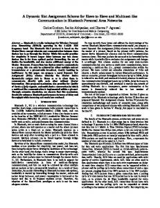
concept is introduced to describe this. The principle of this concept is that there might be some femtocells which have a higher numbers of inbound-handovers than others during the same time period. For the operators, more attention should be paid to these BFemtocells in order to maintain a high quality of service since they have a potentially higher probability to be involved in cross-tier PCI confusion and result in handover failure due to CGI drawback. B. Dynamic PCI Group Assignment In the proposed DG-PCI, PCIs are categorised into three groups - CSG group (Closed Subscriber Group), non-GSG group, and marcocell groups. Furthermore, in CSG and nonCSG groups, PCIs are further categorised into two sub-groups - unique and reuse group, shown in Fig. 1. The PCIs are set according to their group and sub-group, it would be updated depending on the various environments.
Fig. 1.
Proposed Dynamic PCI Group Structure
Since this dynamic PCI group method is similar to the profile of proposed the PCI distribution in [6] and [11], it inherits their advantages such as the fast CSG cell, non-CSG cell and macrocell selection/reselection. The unique PCI group is used to offer unique PCI to BFemtocells. As we know cross-tier PCI confusion may happen when reusing PCIs under the large range of macrocell service, thus, if an approach guarantees unique PCIs being allocated to femtocells, there will be no confusion in inbound-handover. For obvious reason, it is sensible to offer the unique PCI to BFemtocells whenever the system has unique PCI available. C. The Scheme used for Different Access Policys 3GPP defined three types of cell access modes: closed, hybrid and open mode. The following section discusses applying the scheme in different access scenarios. 1) The cross-tier confusion case in different access modes: a) For the closed and hybrid access modes: Cross-tier PCI confusion occurs as follows: during inbound-handover, after UE has determined that this cell is a closed or a hybrid cell, the UE needs to obtain the PCI of the target femtocell to achieve handover. Since there might be multiple femtocells within the coverage of the Serving Radio Network Control (SRNC) that have the same PCI ID,cross-tier confusion may occur.
102
ICWMC 2011 : The Seventh International Conference on Wireless and Mobile Communications
b) For the open access mode: Cross-tier PCI confusion occurs as follows: during the inbound-handover, after the UE has determined that this cell is an open cell, the UE needs to obtain the PCI of the target femtocell to achieve handover. As the femtocell with open access mode operates just like a normal LTE cells, these cells’ PCI could be included in NCL of the macrocell. There might be multiple same femtocell PCI within the NCL of the macrocell which involve the cross-tier confusion issue. c) Comparing these confusion cases in different modes: Three modes contain almost the same process involving the PCI confusion by using the same PCI. Therefore, giving a unique PCI to identify BFemtocells in order to mitigate the drawbacks of CGI is fit for both of the confusion cases.
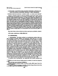
Start
MME collects the network information
Determine which PCIs are using in CSG cell
CN creates the handover report by using network information
OSS uses the handover report to re-allocate PCSG-unique and PCSG-reuse for femtocells
Interval time T
Change PCI request
PCSG-unique>0 Determine the PCSG-unique in CSG unique PCI group
PCSG-unique,0
femtocells change their PCIs in order to mitigate the CGI drawbacks
PCSG-unique=0 Scheme DG-PCI Process CSG mode
Fig. 3.
End
DG-PCI Flow Chat
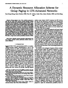
CSG cell. Since non-CSG and CSG have most of the same PCI confusion mentioned early, the process in the proposed scheme for non-CSG and CSG cell scheme can be considered the same process. The author provides the CSG mode flow chat of the proposed scheme process instead of the chat of both the non-CSG and CSG mode. IV. DISCUSSIONS OF THE PROPOSED SCHEME In this section, we will analyse some important issues for DG-PCI. A. Determination of the BFemtocell in LTE Femtocell System Fig. 2.
PCI Distribution in femtocell PCI Group
2) The PCI IDs in different access modes distribute in CSG/non-CSG sub-groups: a) According to release 9, the System Information Block Type1 (SIB1) uses two parameters: CSG-Indication and CSGIdentity: The closed mode cells have a CSG-Identity and CSGIndication bit set to TRUE, hybrid model cells have a CSGIdentity and CSG-Indication bit set to FALSE, open mode cells do not have the CSG-Identity and CSG-Indication bit set to FALSE. b) The PCI IDs in different access modes distribute in CSG/non-CSG sub-groups: Since the CSG-Identity ID involves using the PCI ID [14] and both of the hybrid and close cell mode support CSG-identity ID, closed and hybrid access mode can be treated as the same CSG group, using the set range of PCI IDs (CSG-identity ID). The open access mode is called non-CSG-group also using the set range of PCI IDs (CSG-identity ID). Moreover, there are two sub-groups in each CSG-group/non-CSG group, the PCI in unique PCI sub-groups is used in identification of the BFemtocell which may be CSG or non-CSG mode in order to mitigate the drawbacks of CGI, and also the reuse PCI sub-group is used in identification of the normal femtocell which may be in CSG or non-CSG mode as shown in Fig. 2. D. The Proposed Scheme The DG-PCI Flow Chat is shown in Fig. 3. In the graph, PCSG−unique is the number of unique PCIs for CSG cells; PCSG−reuse is the number of reuse PCIs for
Copyright (c) IARIA, 2011.
ISBN: 978-1-61208-140-3
In a real network scenario, the handover procedure is associated with the Mobility Management Entity(MME). During the inbound-handover, severed femtocell PCI or CGI information is stored in MME. Due to the fact that PCI is dynamically allocated and CGI is statically allocated, in order to ensure the data on the list is available at any time, it is desirable to use CGI ID for data recording. MME is connected with a Home Subscriber Server (HSS), which is responsible for femtocell management, authentication and authorization, the mapping of PCI to the unique CGI and the NCL of each femtocell could be obtained from them [12]. This CGI list will be build by using HSS in order to find the corresponding CGI ID depending on the temporary PCI stored in the MME. After a interval time of T, the MME will send the recorded CGI list to CN. CN will build the BFemtocell list (InboundHandover Report) according to the CGI list and permit OSS [2] to send the updating PCI request to the BFemtocell. B. Graph Colouring-Based Method in Single-Tier PCI Conflict Free The number of unique PCIs is quite an important issue in our scheme. The P CIunique is equal to the total number of PCIs take off the P CIreuse and P CIreuse depends on the single-tier conflict. Reflecting this, the P CIunique is relative to single-tier conflict. We support using Graph Colouring-based mathematical for PCI assignment in order to find the minimum ofP CIreuse and also avoid single-tier PCI conflict in cross-tier LTE femtocell. The method is described as below:
103
ICWMC 2011 : The Seventh International Conference on Wireless and Mobile Communications
Begin Do Sort the new femtocells in order by which femtocell has the highest nNeighbours For (set i=0; i