Dynamic Load Balance for Optimized Message Logging in Fault Tolerant HPC Applications Esteban Meneses, Laxmikant V. Kal´e Department of Computer Science University of Illinois at Urbana-Champaign Urbana, IL 61801, USA {emenese2,kale}@illinois.edu
Abstract—Computing systems will grow significantly larger in the near future to satisfy the needs of computational scientists in areas like climate modeling, biophysics and cosmology. Supercomputers being installed in the next few years will comprise millions of cores, hundreds of thousands of processor chips and millions of physical components. However, it is expected that failures become more prevalent in those machines to the point where 10% of an Exascale system will be wasted just recovering from failures. Further, with such large numbers of cores, fine-grained and dynamic load balance will become increasingly critical for maintaining good system utilization. This paper addresses both fault tolerance and load balancing by presenting a novel extension of traditional message logging protocols based on team checkpointing. Message logging makes it possible to recover from localized failures by rolling back just the failed processing elements. Since this comes at a high memory overhead from logging all communication, we reduce this cost by organizing processing elements into teams and only logging messages between teams. Further, we show how to dynamically partition the application into teams to simultaneously minimize the cost of fault tolerance and to balance application load. We experimentally show that this scheme has low overhead and can dramatically reduce the memory cost of message logging. Keywords-load balancing, causal message logging, fault tolerance.
I. I NTRODUCTION To satisfy the needs of computational scientists for computing power, future computing systems will grow significantly larger and more complex. At the same time, those machines will be more likely to fail. Today’s systems are already known to be vulnerable to system faults. For instance, a study of failures in large systems at the Los Alamos National Laboratory (LANL) found that they failed at a rate of 0.2-0.5 failures/year/processor chip [1]. Further, the 108K-node BlueGene/L at the Lawrence Livermore National Laboratory (LLNL) suffers one L1-cache bit flip every 46 hours and the ASCI Q machine experienced 26.1 cache errors per week [2]. At Exascale, according to the most optimistic projections, the probability that some component will fail will grow so high that 10% of an Exascale system’s time will be wasted just recovering from failures [3].
Greg Bronevetsky Center for Applied Scientific Computing Lawrence Livermore National Laboratory Livermore, CA 94551, USA
[email protected]
Furthermore, as scientists scale their applications to bigger machines, they will face a set of new challenges due to the unique architecture of these supercomputers. Their algorithms will become more sophisticated as they try to incorporate more considerations. For example, adaptive refinements to match the physical space of a simulation may create uneven computation distribution. This will make more complex the task of anticipating the performance characteristics for different scenarios. One inevitable consequence is that programs may exhibit load imbalance for most of the inputs. Some contexts are more susceptible to suffer load imbalance: weather forecast [4], molecular dynamics [5] and cosmology [6]. For all these fields, a smart runtime system working with migratable threads may provide the ideal solution to obtain good load balance and monitor the application to rebalance the load whenever an imbalance occurs again. This paper examines the design of scalable rollbackrecovery protocols for tolerating the effects of component failures. Since global checkpointing requires all processors to roll back when just one of them fails, it will become increasingly more wasteful as the mean time between failures approaches the time to write or read a checkpoint. As such, we focus on message logging protocols that allow one task to recover while others are free to continue their execution. Although traditional message logging protocols must store all application communication, this paper shows how to significantly reduce the storage overhead by partitioning the application tasks into teams and logging only messages between teams. Further, we present an efficient and effective team partitioning algorithm and show that in frameworks that support migratable threads it is possible to combine team partitioning with load balancing. The paper is organized as follows. Section II describes rollback-recovery strategies and Section III introduces the optimized message logging protocol. Section IV shows how to partition processing elements into teams and combine this with traditional load balancing. This approach is experimentally evaluated in Section V. Section VI connects our approach to related work. Section VII concludes the paper.
PE A PE B PE C PE D
Failure
Checkpoint
Early Message
}
Late Message
Time
Time (a) Types of Messages
(b) Global Checkpointing
Time (c) Message Logging
Time (d) Team-based Message Logging
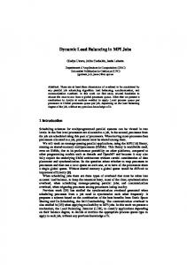
Figure 1: Operation of rollback-recovery protocols.
II. ROLLBACK -R ECOVERY A. System Model The application’s computation is assumed to be divided into a number of objects. Each object has a thread of execution and a private memory. Objects execute concurrently on a set of processing elements (PEs), with one or more objects running on one PE. The distribution of objects onto PEs can be either static or dynamically adjusted by the runtime system. Objects interact by exchanging messages over a network that is reliable but does not guarantee FIFO delivery. The set of all objects is denoted as O and the set of all PEs as P. The fraction |O|/|P| is called the virtualization ratio. We assume it is possible to checkpoint the state of any object at those points in the application where the state of the program is close to its minimal. Either the programmer or a compiler can find those points. This is consistent with application-level checkpointing. The minimum unit of failure is one PE. We assume that PE failures follow the fail-stop model where a failed PE ceases all operation and communication and never recovers. Objects on failed PEs are thus lost. PEs may checkpoint the state of their objects to reliable storage or the memories of other PEs. The frequency of the checkpoints depends on the mean time between failures (MTBF) and can be computed using one of several known methods [7]. When a PE fails we assume that the system has sufficient spare PEs to provide the application with a fresh one. Thus, to recover from a failure, the state of the application’s PEs, including the fresh PE, must be rolled back to a valid state based on the data stored in its checkpoints. The traditional approach for this requires all processes to periodically save the state of the entire application. When one PE fails, all PEs have to roll back to a prior checkpoint to bring the application into a consistent state. However, as the size of systems grows to hundreds of thousands of PEs to reach Exascale performance, the MTBF will grow so low as to make this approach prohibitively expensive [8].
B. Protocols Figure 1 illustrates the fundamental ideas of rollbackrecovery. Suppose for simplicity that one object executes on each of the PEs A, B, C and D. All objects periodically checkpoint their own state, ensuring that some set of checkpoints forms a recovery line (shown as the bold line connecting checkpoints and/or current states). If a recovery line is not crossed by any communication, recovering objects may compute as normal. Suppose, however, a recovery line is crossed by some message from PE D to PE C that was sent before D checkpointed and was received after C checkpointed (denoted Late Message). On restart it will not be replayed by D but will be expected by C. To recover from such a recovery line is necessary to record the data of all late messages in a log and on restart to replay them for their receivers from the log. This provides the illusion that they were in-flight at the time of the checkpoint. Similarly, consider a message from B to A that was sent after B checkpointed and received before A did (denoted Early Message). Such messages will be resent by B on restart but A will not be ready to receive them, which means that they must be suppressed on restart. Further, if there are any non-deterministic events between the checkpoint on B and the send of this message, their outcomes must be recorded during the original execution and they must be replayed exactly the same way on restart because A’s state in its checkpoint depends on their original outcomes. Traditional checkpointing is shown in Figure 1(b). When some PE fails and its objects are lost, all PEs roll back to the checkpoints of a recovery line and resume computation. Checkpointing protocols manage late and early messages in a wide variety of ways, from ensuring that early and/or late messages cannot exist (via coordinated checkpoint) to performing the appropriate logging [9]. Since checkpointing protocols require all objects to roll back whenever any one of them fails, message logging protocols were developed to enable just the failing objects to roll back and allow the others to continue execution as
Team X
Recovery Line
PE A
MLOG DLOG
α
PE B
MLOG
β
DLOG
γ
PE C
MLOG DLOG
m1 m2
m3⊕d1⊕d2
ACK
δ Time
Figure 2: Simple Causal Message Logging.
normal. Figure 1(c) illustrates this. Since only the failing PE rolls back, the recovery line connects the failed object’s checkpoint to the current state of the non-failed objects. This means that any messages sent by the failed object after its checkpoint are early and any messages received by it since the checkpoint are late. As such, message logging protocols must log the data of all messages and the outcomes of all non-deterministic events as the price of providing a more flexible recovery. Recently, there has been work to combine the two families of protocols to provide flexible recovery with a low logging overhead [10]. The idea, illustrated in Figure 1(d), is to group PEs into teams. PEs within each team use a traditional checkpointing protocol, where if a PE of any team fails, all PEs in the team must roll back and restart. Message logging is used for communication between teams, so if one team rolls back, others can continue work without interruption. This means that only messages across teams must be logged, although all non-determinism must still be logged. Team-based message logging can be seen as a compromise between global checkpointing and message logging. If there is only one team, it is equivalent to global checkpointing, whereas if the number of teams equals |P|, it is equivalent to message logging. III. O PMITIZED M ESSAGE L OGGING This paper presents and evaluates techniques for dynamically managing the division of application objects into teams based on their computation and communication requirements. It is performed in the context of a specific combination of checkpointing and message logging protocols. All PEs belonging to the same team checkpoint coordinately. Communication inside a team and between teams is managed using the causal logging protocol [11], [12]. This protocol logs the data of outgoing messages to ensure that if the receiver fails, the messages it received since its last checkpoint will be re-sent to it. Outcomes of non-deterministic events (called determinants) on a given object are logged away from the object so that if it fails, it can recover them from surviving portions of the system.
The prime example of a non-deterministic event is message reception. The insight of causal logging is that the reason to save non-deterministic events on a given object is because other objects may depend on them. As such, if the object restarts and executes these events differently, the states of these other objects may become inconsistent with these new post-restart outcomes. As such, it lazily waits to save each event e on an object o until the point in time when another object r may depend on its outcome, which happens when o sends a message to r after performing event e. Since r is the reason for e being saved, e’s outcome is attached to the message to r, making r responsible for storing its outcome. There are extensions of causal logging that ensure that the outcome of each event is replicated on at least some number of PEs. Our evaluation focuses on the variant that maintains one redundant copy of each determinant. On object hα, Ai: Non-Deterministic Event generates determinant d Store d in dets(A) On object hα, Ai: Send(m, hβ, Bi) if A and B are NOT on same team then α stores m in M LOG(A) end if if A 6= B then SendNetwork(hβ, Bi, m, dets(A)) else SendNetwork(hβ, Bi, m, ∅) end if On object hβ, Bi: Receive(m, dets) from object hα, Ai Store dets in DLOG(B) Deliver(α, m) SendNetwork(ACK, A) On PE A: ReceiveACK(d) from PE B Remove d from dets(A) Figure 3: Pseudocode of team-based causal message logging. Figure 2 depicts the basic operation of simple causal message logging. We can see four objects (α, β, γ and δ) distributed into three PEs in the system (A, B and C). Let’s imagine α sends message m1 to β. After receiving m1 , β generates a determinant for m1 , denoted by d1 . Later on, γ sends m2 to β and another determinant, d2 , is generated at β. Now, β will piggyback these determinants on all the next outgoing messages until it receives a confirmation that the determinants are safely stored. For instance, when β sends m3 it has to piggyback the two determinants. We represent the piggyback operation by the symbol ⊕. Once
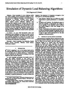
IV. L OAD BALANCING In prior work we evaluated a simplified version of the team-based approach with pessimistic message logging on various applications [10]. Our experiments demonstrated the value of this method, showing that memory used by message logs was reduced by 73% in NPB-CG using teams of 16 PEs each. However, this work was limited because the teams were created by grouping each consecutive set of 16 PEs into a team and maintaining this static team assignment for the entire execution. This simple approach can result in poor performance if it causes most communication to cross team boundaries because all such communication will need to be logged. Further, such a static assignment is unlikely to perform consistently well for applications where the communication pattern changes over time. Communication characteristics may change due to load imbalance in the application. As such, it is necessary to ensure that the partitioning matches the application’s communication pattern and tracks this pattern as it evolves over time. The communication patterns of parallel computing programs are usually well-structured since such structures are easier to implement and optimize and because large patterns are composed of smaller patterns from individual kernels. Figure 4(a) presents the communication topology of a 256-rank instance of the Conjugate Gradient NAS Parallel Benchmark, Class D. Each point represents the number of messages exchanged by a pair of ranks, with brighter points corresponding to more messages. The figure shows a clear pattern of numerous clusters of 16 tightly connected
ranks. Thus, best performance will be achieved if each checkpointing team included one or more such clusters since only inter-cluster communication must be logged. The same lesson applies to applications with dynamic communication patterns, such as NAMD [5], where the choice of teams must evolve to provide good performance throughout the application’s execution. While some applications have simple regular patterns, others have a more complex locality structure. Figure 4(b) shows the communication topology for a 256-rank instance of the multi-zone version of the Block Tri-diagonal NAS Parallel Benchmark, Class C. It this case, we see a very different pattern, where it is more difficult to spot the clusters by a simple look. The next section analyzes this case more deeply, showing a general algorithm to partition arbitrary communication patterns into teams.
0
1
2
3
4
5
6
7
8
0
2
Thousands of Messages
4
6
8
10
12
Megabytes
250
250
200
200
Receiver Rank
Receiver Rank
δ receives m3 and determinants d1 and d2 , it will return an ACK message to β for it to stop piggybacking those two determinants. Figure 2 also presents the two sources of memory overhead for any message logging protocol. First, and more important, we have the message log (MLOG) that stores all the outgoing messages. Depending on the size of the messages and the communication dynamics of the application, this overhead can quickly become a major concern. Second, the determinant log (DLOG) has to store the determinants produced in other PEs. Figure 3 shows the pseudo-code of the causal message logging algorithm that has been adapted to work with teambased checkpointing. Objects are denoted hα, Ai, where α is the object and A is the PE it runs on. The data structure that temporarily stores the determinants generated at PE A is called dets(A). Determinants in dets(A) must be piggybacked in outgoing messages until they are safely stored in other PE. We call our protocol optimized message logging, primarily for two reasons. First, it is based on simple causal message logging, which we recently showed has a smaller execution time penalty [11]. Second, it incorporates the team-based approach which we demonstrated may reduce dramatically the memory overhead of message logging [10].
150 100 50
150 100 50
0 0
50
100 150 Sender Rank
(a) NPB-CG
200
250
0 0
50
100 150 Sender Rank
200
250
(b) NPB-BT multi-zone
Figure 4: Communication Topology. Given the importance of providing high-performance fault tolerance for future HPC systems we have designed a technique to minimize the overhead of message logging dynamically assigning PEs to teams. The assignment (i) minimizes communication to reduce the cost of logging cross-team messages and (ii) ensures that computational work is balanced across PEs. Team work assignments must be balanced to ensure that the amount of work lost due to a failure is consistent across all possible failures. Further, balanced assignments work to PEs ensure that computational resources are used efficiently. Our algorithm satisfies these goals by using a graph partitioning algorithm to map objects into teams of PEs and using a greedy load balancing algorithm to assign objects within each team to PEs. A. Graph Partitioning We represent the application as an undirected graph G = (V, E), where V is a set of weighted vertices and E is a set of weighted edges. Vertices represent objects and their weights correspond to the amount of compute work performed by each object. Edges represent communication between objects and their weights represent the amount of message traffic in terms of the total amount of message data.
PE B
PE C
PE D
Step 2
Team Y
Step 1
PE A
Team X
Team X
Team Y
Figure 5: Load Balancer Architecture.
The goal is to partition this graph’s vertices to minimize the weights on the edges across partitions (also called the edge cut) and produce partitions with approximately equal sums of vertex weights. This task can be done by a variety of graph partitioning tools, most notably METIS [13] and SCOTCH [14]. These libraries usually implement one of two major algorithms for graph partitioning. In an approach called multilevel partitioning, the initial graph is first coarsened by merging vertices that look like promising members of the same cluster. Then, the graph is partitioned at that point to get into a refinement phase, where the partitioning will be performed with finer vertices. In contrast, recursive bipartitioning splits each sub-graph into two smaller sub-graphs until the whole graph reaches the required number of partitions. B. Load Balancing Framework After the graph is partitioned into teams it is necessary to assign individual objects to PEs. This is done by greedily assigning objects to minimize the variance between the load on different PEs. The algorithm iterates through the objects and assigns each object, which has load l, to the PE that minimizes the function I=
maxl − avgl avgl
where maxl is the maximum load assigned to any PE and avgl is the average assigned load. Figure 5 shows the load balancing process. The set of objects and their communication graph are displayed at the left, with objects that have a heavier load shown in a darker color. For simplicity the edges among objects all have the same weight. We first apply graph partitioning (Step 1) to divide the objects into teams X and Y that minimize cross-team communication. We then balance load within each team to minimize I (Step 2). Since the clustering algorithm balances load across teams and the greedy algorithm balances load among PEs within a team, this results in a globally balanced load assignment.
V. E XPERIMENTAL E VALUATION A. Software Infrastructure We chose to implement the multi-level load balancer described in the previous Section in C HARM ++, since it provides all the required infrastructure to experiment with adaptive techniques for HPC. C HARM ++ is a parallel programming language and a model for parallel computation based on message-driven object decomposition [15]. A C HARM ++ programmer conceptually decomposes the computation into objects, or chares, in a way that is independent of the number of physical processors the application will run on. This independence on the actual number of processors enables the programmer to overdecompose the program and create a collection of objects that will be mapped, migrated and scheduled on the processors by an intelligent runtime system. The system manages failures using one of several fault tolerance protocols.
(a) Imbalanced Execution
(b) Balanced Execution
Figure 6: Load imbalance in NPB-BT multi-zone. The C HARM ++ framework also supports Adaptive Message Passing Interface (AMPI) [16], which enables MPI programs to run on top of C HARM ++, allowing them to leverage its load balancing and fault tolerance features. AMPI permits us to evaluate the proposed algorithm with any MPI program. C HARM ++ provides a flexible interface to define various load balancers. The load balancing infrastructure collects information about the load of every object in the system and its communication with other objects. This information, along with the current mapping of objects to PEe, is passed to any load balancer which returns a new mapping for the objects. In the C HARM ++ nomenclature, a load balancer implementing a particular strategy is called StrategyLB. For instance, the implementation of the technique laid out previously on this paper is called TeamLB. We used SCOTCH graph partitioning library to implement TeamLB and we used the default partitioning strategy in SCOTCH. B. Experimental Setup All our experiments were run on Steele supercomputer at the Rosen Center for Advanced Computing (RCAC). Steele has 893 nodes with 16GB of memory each and connected through Ethernet for a total peak performance of 60 TFlops. We evaluated our team-based logging protocol on the applications described in Table I. The common factor of
all of them is that they show load imbalance. If the load balance is static it means applying the load balancer once is sufficient to balance the load. The dynamic load imbalance requires the periodic application of the load balancer.
Mol3D Biophysics Charm++ Dynamic
LBTest Synthetic Charm++ Dynamic
The multi-zone version of the NAS Parallel Benchmarks (NPB) compute discrete solutions in three spatial dimensions for the unsteady and compressible Navier-Stokes equations. There are three different benchmarks, Lower-Upper symmetric Gauss-Seidel (LU), Scalar Penta-diagonal (SP) and Block Tri-diagonal (BT). We chose, however, to experiment with BT since it presents the highest load imbalance among the three. BT solver operates on a logical cube that is seen as a structured discretization mesh. Nevertheless, to describe a complex domain, BT uses multiple meshes (called zones) to cover it. Mol3D is a molecular dynamics program that simulates biomolecular systems by computing the forces between the atoms of different molecules. Mol3D is based on the same technology as NAMD [5] and reads the same input format. Mol3D has two sets of objects: patches which cover all the tri-dimensional space to simulate and computes which are in charge of computing the interaction forces between the atoms in the patches. Finally, LBTest is a synthetic benchmark in C HARM ++ for load balancing experimentation that creates a collection of objects with different customizable properties. Its parameters include the communication topology among the objects, a range for the load of objects, frequency of load balancing and whether the load in each object changes across the execution. This program allows us to analyze the effect of one single parameter at a time and measure how susceptible the load balancer is to different scenarios. C. Results We start by illustrating the effects of load balancing on a relatively small-scale application: NPB-BT with Class C input, 256 ranks and 64 cores on Abe. At this scale, it is possible to visually examine the load on each core. Figure 6 shows the load distribution across all the cores during a run of the benchmark. Each plot shows the percentage of CPU load on each core, with the Figures 6(a) and (b) showing the load distribution without a load balancer and with our load balancing algorithm, respectively. The load distribution without load-balancing is very skewed, with the first core spending more than 95% of the time in processing, while the last core has below 5% CPU utilization. The average of processor utilization is just 27% and load imbalance I is
280
108 96 84
240
72
200
60
160
48
120
36
80
24
40
12
0 Execution Time
Memory Overhead
Memory (MB)
Field Language Load Imbalance
NPB-BT Algebra MPI Static
NoLB(8) GreedyLB(8) TeamLB(1) TeamLB(8)
320
Time (seconds)
Table I: Applications
NPB-BT multi-zone (64 PEs, Steele) 360
0
Figure 7: Performance comparison of various load balancers.
2.52. Figures 6(b) shows that our algorithm can dramatically improve the application’s load balance. When our algorithm is employed after iteration 10 (out of 200), the distribution of load becomes much more even. The average CPU utilization improves to 59% and the load on all cores is consistently close to this level. Load imbalance I is brought down to 0.32. In this case we used 8 teams with 8 cores per team. It is clear that load imbalance is an inherent feature of NPB-BT multi-zone. Equally important is to know what its communication features are. Figure 4(b) presents the communication volume topology for this benchmark. As opposed to figure 4(a), it is not obvious what the clusters are. Nevertheless, this communication graph has a clustering structure. Applying SCOTCH to this graph and looking for a partition into 8 teams gives us an edge cut ratio of 0.18. This is, only 18% of the total number of bytes sent between different ranks crosses team boundaries. Another feature of figure 4(b) is that it shows a skewed distribution of the communication volume across ranks. Lower index ranks tend to communicate more bytes than higher index ranks. Indeed, there is a small positive correlation (index of 0.32) between the distribution of load (figure 6(a)) and communication volume of application ranks. Figure 7 compares the performance of the team-based load balancer to four others on NPB-BT. The numbers in the parentheses denote the team size. In all the cases, the mechanism to form teams consists in grouping consecutive PEs to make a team. All teams have the same number of PEs but not necessarily the same number of objects. We measured the benchmark’s execution time and memory used to store message logs for recovery. The NoLB creates teams of PEs but does not migrate objects across PEs. Not surprisingly, it has the worst performance. The GreedyLB algorithm maps the heaviest object to the least loaded core. This reduces the execution time dramatically, for a speedup of 2.12x. This algorithm has the least load imbalance but
NoLB TeamLB
2
512
NoLB TeamLB
Execution Time (seconds)
Speedup
Mol3D (Steele)
NPB−BT multi−zone (Steele)
2.5
1.5 1 0.5 0
64(C)
128(C) 256(D) 512(D) Number of PEs
1,024(E)
Figure 8: Scaling NPB-BT multi-zone with TeamLB.
256
128
64 128
256 512 Number of PEs
1024
Figure 9: Strong scaling benchmark APOA1 with Mol3D. increases the message log size. The TeamLB algorithm changes the execution time little compared to GreedyLB, with just 1% and 2% overhead for team size 1 and team size 8, correspondingly. This slight performance reduction is caused by its somewhat worse load imbalance. Team size 1 increases the message log to the maximum because of the small team sizes but produces the smallest logs, when using 8-core teams. This is just 56.73% of GreedyLB’s logs. These results show that team-based load balancing significantly improves the amount of memory required for logging messages while having a minimal effect on the application’s failure-free performance. We analyzed the 8 clusters generated by TeamLB in figure 7. That partition has an edge cut ratio of 0.26, which is 0.08 higher than what SCOTCH would do without considering the load of the objects. In other words, we have to log an additional 8% of the total number of bytes sent if we account for load balance when the teams are been formed. Since we originally had 256 objects, on average each team had 32 objects, but with a high dispersion of the data. Standard deviation in the number of objects per team was 13.76, or a coefficient of variation equals to 0.43. The maximum and minimum cluster size were 53 and 19, respectively. Figure 8 shows the difference in NPB-BT performance with the NoLB and TeamLB algorithms as the number of PEs is scaled from 64 to 1024 on Steele. Experiments at all scales used 8 teams and we focused on weak scaling. Classes C, D and E were run with 256, 1024 and 4096 objects, respectively. The data shows that the ratio of objects to PEs has little effect on the speedup. With class C we obtained speedups of 2.12 and 2.04 for 64 and 128 PEs, respectively. For class D, speedups of only 1.21 and 1.20 were obtained for 256 and 512 PEs. Class E showed an speedup of 1.17 on 1024 PEs. In the second scaling experiment we analyzed what happens when we strong scale the Mol3D molecular dynamics benchmark. Mol3D was executed on the APOA1 benchmark problem, which models a bloodstream lipoprotein particle that has around 92,000 atoms. Figure 9 presents the results with and without TeamLB. We can see it makes sense to
apply load balancing in the whole scale. Starting at 128 PEs, the speedup is 2.23. It is reduced to 1.82 at 256 PEs. For 512 PEs it reaches 1.49 and it finishes in 1.16 at 1024 PEs. To study load balancer’s ability to adjust to dynamic changes in load and communication we evaluated it with the LBTest benchmark, which can be configured to simulate a wide range of communication behaviors. The communication topology was a three-dimensional mesh, where each object had 6 other neighbors. There were 4096 objects in total and all of them executed 50,000 iterations. In each iteration, every object sent a 1KB message to its neighbors and waited for their reply before computing for t microseconds. The value t varied in the range of 100 to 1,200 microseconds. Each object started with the same value of t equal to the midpoint of this interval and during execution the t value of each object drifted toward one of the extremes. At the end of execution, the object with ID 4095 had a t value equals to the upper limit in the interval, whereas object ID 0 had a t value equals to the lower limit. The rest of the objects had an execution time linearly distributed in the interval. Figure 10 shows the LBTest’s performance in terms of the time per iteration for an execution of 50,000 iterations where the load balancer was applied every 10,000 iterations. When no load balancing is performed, the imbalance and iteration times increase steadily. The team-based load balancer eliminates this imbalance, resulting in drops in iteration times every 10,000 iterations. TeamLB ultimately causes a factor of 1.23 speedup in this benchmark. Since load balancing is easiest when computational and communication load are uncorrelated, we studied TeamLB’s limits by measuring its performance in the more complex case where they are correlated. We did this by parametrizing LBTest to have the most heavily-loaded object send the largest messages and use the highly clustered communication topology from NPB-CG shown in figure 4(a). Since NPB-CG has a simple cluster structure, we divided load unevenly among objects. Lower indexed objects computed
LBTest (256 PEs, Steele)
Mol3D (256 PEs, Steele) NoLB TeamLB
14
Edge Cut (ratio)
Time per iteration (milliseconds)
1 12 10 8 6 4 2 0
10000
20000 30000 Iteration
40000
0.6 0.4 0.2 0
NoLB TeamLB
0
0.8
50000
8
16 32 Team Size (PEs)
64
Figure 11: Effect of team size in edge cut ratio.
Figure 10: Dynamic load imbalance in LBTest.
less and the distribution was increasingly linear up to the last object, which had the most computation. Thus, we created light clusters with very low load and heavy clusters with most of the computation time. We then compared the two different scenarios. In the uncorrelated case, object would send a message whose size was not related to the current load. On the other side, in the correlated case, heavier objects would send larger messages. The results of table II show that correlation of load and message size in a clustered application hurt the performance of TeamLB. Although the execution time was marginally affected, the portion of the edge cut that was not captured by the teams increased by 6%. Table II: Load and Message Size Correlation Execution time (seconds) Edge cut (ratio)
Uncorrelated 115.09 0.47
Correlated 118.90 0.53
Finally, we decided to show the effect of team size on the amount of data that can be contained inside the teams. Although it is clear that larger teams should decrease the edge cut, it is not easy to see by what margin. We ran Mol3D on the APOA1 problem with 256 cores on Steele and compared the results after changing the team size. We ran the test with (i) a simple team selector that uses no load balancing and assigns PEs to teams randomly and (ii) the TeamLB algorithm. Figure 11 presents the comparison of the two scenarios, showing that TeamLB is superior to the random approach. VI. R ELATED W ORK The idea of improving rollback-recovery techniques by decomposing an application into subgroups of tasks has been applied in various scenarios in the past. Monnet et al presented the hybrid checkpointing approach [17] to facilitate the checkpoint of applications running on federated clusters. An application is run on several supercomputers.
Each machine coordinately checkpoints the state of the tasks running on it and communication induced checkpoint with optimistic message logging are used to create a recovery line across machines. They used a simulator to test their algorithm. Wei et al [18] offered a purely theoretical framework to combine checkpoint in atomic subgroups of tasks with message logging. They based their algorithm on checkpoint dependency graph (CDG) and formally demonstrated different properties of this technique. Specifically in parallel computing, Yang et al proposed a partitioning of the ranks of an MPI program into groups to improve the efficiency of rollback-recovery protocols [19] In their algorithm, ranks are divided into g clusters, causal message logging is used inside a cluster and pessimistic message logging is used across clusters. Changing the number of clusters changes the system’s performance both during normal execution and during recovery. Each cluster checkpoints independently of the rest and it is assumed that each cluster has approximately synchronized clocks. No coordination among ranks of the same cluster is performed. Clusters are static and created at random. Performance results include applications up to 16 ranks. Ho et al [20] proposed a group-based checkpoint/restart scheme to avoid rolling back all the ranks in an MPI application in case of a failure. They presented an algorithm to obtain the clusters out of the communication topology of an application. The number of clusters is not an input to the algorithm, but an output of it. Message logging is used to store messages across groups, but applications have to be deterministic. All partitions are static and their implementation on LAM/MPI scaled up to 144 ranks. Singh and Graham [21] studied groups of MPI ranks in applications in order to perform partial checkpoint and co-migration. Their work targets Grid architectures were overloaded machines may involve a significative loss in performance. By having a group of closely related MPI ranks, a group of tasks could be migrated away from overloaded processors and avoid a decrease in performance. A pattern matching algorithm statically forms the groups. Results did not scale beyond 8 processors.
VII. C ONCLUSIONS AND F UTURE W ORK As computational scientists scale their applications to larger machine sizes, they will face at least two major challenges: frequent failures and load imbalance. This paper argues that we can tackle both in a combined fashion. Using graph partitioning tools we created a load balancer that has a small execution time overhead (below 3% for NPB-BT multi-zone) and that can create groups to drastically reduce the storage overhead of message logging. The results showed that our scheme can scale to large system sizes, providing high performance and low storage overhead. We showed that although correlations between computation load and communication intensity present a challenge to our approach, the effect on application performance is minimal. In our future work we will examine the effectiveness of our approach on applications from a wider range of scientific domains, such as adaptive mesh refinement (AMR) applications. ACKNOWLEDGMENTS This research was supported in part by the US Department of Energy under grant DOE DE-SC0001845 and by a machine allocation on the Teragrid under award ASC050039N. This work was partially performed under the auspices of the U.S. Department of Energy by Lawrence Livermore National Laboratory under Contract DE-AC52-07NA27344. R EFERENCES [1] B. Schroeder and G. Gibson, “A large scale study of failures in high-performance-computing systems,” in International Symposium on Dependable Systems and Networks (DSN), 2006. [2] S. Michalak, K. W. Harris, N. W. Hengartner, B. E. Takala, and S. A. Wender, “Predicting the Number of Fatal Soft Errors in Los Alamos National Laboratory’s ASC Q Supercomputer,” IEEE Transactions on Device and Materials Reliability, vol. 5, no. 3, 2005. [3] P. Kogge, K. Bergman, S. Borkar, D. Campbell, W. Carlson, W. Dally, M. Denneau, P. Franzon, W. Harrod, J. Hiller, S. Karp, S. Keckler, D. Klein, R. Lucas, M. Richards, A. Scarpelli, S. Scott, A. Snavely, T. Sterling, R. S. Williams, and K. Yelick, “Exascale computing study: Technology challenges in achieving exascale systems,” 2008. [4] E. R. Rodrigues, P. O. A. Navaux, J. Panetta, A. Fazenda, C. L. Mendes, and L. V. Kale, “A Comparative Analysis of Load Balancing Algorithms Applied to a Weather Forecast Model,” in 22nd SBAC-PAD, Itaipava, Brazil, 2010. [5] J. C. Phillips, R. Braun, W. Wang, J. Gumbart, E. Tajkhorshid, E. Villa, C. Chipot, R. D. Skeel, L. Kal´e, and K. Schulten, “Scalable molecular dynamics with NAMD,” Journal of Computational Chemistry, vol. 26, no. 16, pp. 1781–1802, 2005. [6] F. Gioachin, A. Sharma, S. Chakravorty, C. Mendes, L. V. Kale, and T. R. Quinn, “Scalable cosmology simulations on parallel machines,” in VECPAR 2006, LNCS 4395, pp. 476489, 2007.
[7] J. T. Daly, “A higher order estimate of the optimum checkpoint interval for restart dumps,” Future Generation Comp. Syst., vol. 22, no. 3, pp. 303–312, 2006. [8] F. Cappello, “Fault tolerance in petascale/ exascale systems: Current knowledge, challenges and research opportunities,” IJHPCA, vol. 23, no. 3, pp. 212–226, 2009. [9] G. Bronevetsky, D. Marques, K. Pingali, and P. Stodghill, “Automated application-level checkpointing of MPI programs,” in PPoPP’03, 2003. [10] E. Meneses, C. L. Mendes, and L. V. Kale, “Team-based message logging: Preliminary results,” in 3rd Resilience, May 2010. [11] E. Meneses, G. Bronevetsky, and L. V. Kale, “Evaluation of simple causal message logging for large-scale fault tolerant hpc systems,” in 16th DPDNS, May 2011. [12] L. Alvisi and K. Marzullo, “Message logging: pessimistic, optimistic, and causal,” Distributed Computing Systems, International Conference on, vol. 0, p. 0229, 1995. [13] George Karypis and Vipin Kumar, “Multilevel k-way Partitioning Scheme for Irregular Graphs,” Journal of Parallel and Distributed Computing, vol. 48, pp. 96–129 , 1998. [14] F. Pellegrini and J. Roman, “Scotch: A software package for static mapping by dual recursive bipartitioning of process and architecture graphs,” in HPCN Europe, 1996, pp. 493–498. [15] L. Kal´e and S. Krishnan, “CHARM++: A Portable Concurrent Object Oriented System Based on C++,” in Proceedings of OOPSLA’93, A. Paepcke, Ed. ACM Press, September 1993, pp. 91–108. [16] C. Huang, O. Lawlor, and L. V. Kal´e, “Adaptive MPI,” in Proceedings of LCPC 2003, College Station, Texas, October 2003, pp. 306–322. [17] S. Monnet, “Hybrid checkpointing for parallel applications in cluster federations,” in Proceedings of CCGRID’04, 2004, pp. 773–782. [18] Z. Wei, H. F. Li, and D. Goswami, “A locality-driven atomic group checkpoint protocol,” in PDCAT, 2006, pp. 558–564. [19] J.-M. Yang, K. F. Li, D.-F. Zhang, and J. Cheng, “A coarsegrained pessimistic message logging scheme for improving rollback recovery efficiency,” in Third DASC. Washington, DC, USA: IEEE Computer Society, 2007, pp. 29–36. [20] J. C. Y. Ho, C.-L. Wang, and F. C. M. Lau, “Scalable groupbased checkpoint/restart for large-scale message-passing systems,” in IPDPS, 2008, pp. 1–12. [21] R. Singh and P. Graham, “Grouping mpi processes for partial checkpoint and co-migration,” in Euro-Par, 2009, pp. 69–80.