Dynamic Load Balancing through Backup Relay in Bluetooth Scatternet Sheikh Tahir Bakhsh
Halabi Hasbullah
Department of Computer and Information Sciences, Universiti Teknologi PETRONAS, Bandar Seri Iskandar, 31750 Tronoh, Perak, Malaysia
Department of Computer and Information Sciences, Universiti Teknologi PETRONAS, Bandar Seri Iskandar, 31750 Tronoh, Perak, Malaysia
[email protected] [email protected] Fazli Subhan Department of Computer and Information Sciences, Universiti Teknologi PETRONAS, Bandar Seri Iskandar, 31750 Tronoh, Perak, Malaysia
Sabeen Tahir
[email protected]
Aamir Saeed
[email protected]
[email protected] ABSTRACT A mobile ad-hoc network (MANET) is a collection of wireless mobile nodes, which creates an infrastructure less temporary network. Bluetooth is a short range, low-cost, and low power wireless technology. Bluetooth allows communication among electronic devices through a basic network called piconet. One device controls piconet, which is called master and other act as slaves. Multiple piconets may exist in Bluetooth network known as scatternet. The connection among different piconets is provided through a common node known as relay. Relay is connected with more then one master with different hopping pattern, relay node forwards data among different piconets. The degree (number of connection) of relay has a serious impact on network performance. The larger degree relay increases packet loss rate and transmission delay, and it has to switches among different piconets that also increase scheduling overhead. This paper considers the problem of designing an effective Dynamic Load Balancing (DLB) technique to share traffic load through Backup Relay (BR). The proposed technique avoids bottleneck and reduces transmission delay. The simulation is also conducted to show the supremacy of proposed work by using UCBR that is an extension of NS-2. Proposed technique reduces packet loss moreover it increases throughput and network lifetime.
Keywords Bluetooth, Dynamic, Load Balancing, Backup Relay.
1. INTRODUCTION Bluetooth (BT) is a promising Wireless Personal Area Networks (WPAN) standard for short range ad hoc wireless networks [1]. Initially, Bluetooth was launched as cable replacement technology therefore, initially radio frequency (RF) range of BT devices was 10 meters. Bluetooth uses a set of RF frequencies (79) and it Permission to make digital or hard copies of all or part of this work for personal or classroom use is granted without fee provided that copies are not made or distributed for profit or commercial advantage and that copies bear this notice and the full citation on the first page. To copy otherwise, or republish, to post on servers or to redistribute to lists, requires prior specific permission and/or a fee. FIT’10, December 21-23, 2010, Islamabad, Pakistan. Copyright 2010 ACM xxx-x-xxxxx-xxx-x/xx/xx....$10.
works at about 2.4GHz. Frequency Hopping Spread Spectrum (FHSS) technique is utilized by BT to avoid interference. A BT device hopping sequence is determined from the piconet master and Bluetooth Device Address (BD_addr) that is known as channel [2]. Each channel is divided into 625µs time slot, BT device channel is synchronized with the clock of its master. A BT device uses different frequency in each time slots and its medium access based on Time Division Duplex scheme.
1.1 Bluetooth Communication Bluetooth allows communication through piconet. A piconet contains maximum eight active BT devices that include one master and seven active slaves at a time. The master manages and schedules data transmission and channel allocation to its slaves [2]. A master sends packet to slave in even-numbered slots and slave replies to master in subsequent odd-numbered slot. Slaves are allowed only to send packet in response of master’s packet. All slaves listen the master, slave is allowed to transmit only after being addressed by the master. Data are transmitted in the form of packets, each packet can be long 1, 3 or 5 slots. Each packet is transmitted on different frequency, the frequency changing is called fast hopping that increase the communication reliability. Slave maintains a queue of packets sent to be master and master has a unique queue for each of active slave. When there is no data for slave in his turn master sends zero payload POLL packets to slave in response slave sends NULL packet to the master.
1.2 Scatternet in Bluetooth Bluetooth devices belong to different piconets cannot communicate directly although, their distance from each other is smaller than radio communication range. The reason is that their channel hopping sequence is different [3] from each other. It is more complex structure when joining two piconets, inter-piconet communication is possible through scatternet that consists of multiple piconets. A mobile node that participates in multiple piconets has to play role of a relay/bridge. A relay can be S/S (Slave/Slave), which concurrently participates in more than one piconet as slave or M/S (Master/Slave) a relay that plays master role in one piconet and slave role in other piconets [4]. A relay can be slave more then one piconet but the role of master can be played only in one piconet. The reason is if two piconets have
same master then there frequency hoping would be same that causes interference in network. A relay shares its time among all the piconets in which it participates, relay switches from one piconet to another in a cyclical sequence. The source piconet master delivers data to relay during its residence in piconet [5]. The duration of relay in each piconet and switch-over time is arranged by the chosen bridge scheduling algorithm [5, 18]. Bluetooth allows only synchronize transmission so every time a relay needs to re-synchronize its clock according to the present piconet master clock. A relay needs 3 slots for synchronization, if degree of a relay is higher that creates delay in network. The scatternet routing and piconet communication has not defined in the Bluetooth specification [2]. The bridging function also does not exist in Bluetooth specification and it is handled by layer protocol stack which affects system performance.
1.3 Relay Role in the Scatternet A master switches to inquiry state before adding a new slave and gets clock information and BD_addr (48-bit). When master changing paging state it assigns a unique 3-bit Active Member Address (AM_Addr) to active slaves on the channel that is extracted from BD_addr and clock information. The AM_Addrs range is 1-7 or in binary (000-111), if AM_Addrs reach to its limit after that no AM_Addr can be assigned to new slave. Thus, AM_Addr is a useful resource, if a relay participates in (n) piconets it consume (n) AM_Addrs that increase network managing overhead. Bluetooth is a special type of ad-hoc network, BT has two type of routing protocols; table driven [14] and on-demand [15, 16, 17] routing protocol. In the literature, a number of papers [6, 7, 8, 9, 10] have been used to develop routing protocols for Ad-Hoc networks. Packet flooding is broadly used for routing from source host to destination. When a route is required most of routing protocols flood a broadcast query to find the destination. When any node receives route request packet it replies to query, it forwards the broadcast query if it is not the required destination. Source host try to find the shortest path by considering all the possible paths. A Routing Vector Method (RVM) [7] is a routing protocol that based on flooding scheme. RVM is an on-demand routing protocols, it floods a route search request to find destination. When destination device receives the first route search packet it replies to the query and constructs route. RVM depends on network structure for efficient route, its main drawback is longer route and inefficient flooding due to unnecessary relays. Relay reduction and disjoint routes construction (LORP) [6] uses the RVM as base to reduce distance between source and destination in addition, LORP reduces lower degree of unnecessary relays. Although, huge amount of relays are beneficial for less disconnection and fast flooding but it uses extensive packet flooding that increases scheduling overhead in network. LORP has still some weaknesses it does not considers traffic load, if load increases on a relay that causes bottleneck and frequent network disconnection. The main contribution of proposed works is summarized as follows: This paper presents a technique to avoid bottleneck and increases lifetime of network by sharing traffic load. The rest of the paper is organized as follows Section 2 discusses the overview of related works, relation between relay and piconet. Dynamic Load
Balancing technique is presented in section 3. The performance of the proposed protocol and its comparison with some standard protocols are discussed in Section 4. Finally conclusion of proposed work is drawn in Section 5 of the paper.
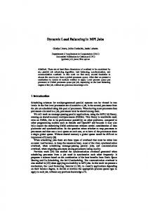
2. RELATED WORKS Bluetooth device has to play one of the three roles, master, relay or slave. Master manages piconet and relay connects different piconets. Bluetooth does not perform the global scheduling all piconet masters perform locally decision [11, 12, 13]. So for some work has been done to changing role of devices and alter the network structure [20, 18], but main bottleneck point is still neglected i.e. relay. It is analyzed that a large number of piconets traffic pass through a single relay reduce the system throughput. If a piconet is congested, means all seven slaves are active and their destination is in different piconet. If one relay provides connection among different piconets, so throughput of system will not be optimized. If multiple links pass through a single relay, when a relay serves one link, other traffic is blocked due to unavailability of relay. When relay time ends in first link it switches to other piconet and allows transmission, which causes bottleneck in the network. A relay node consumes more energy comparative slave, when relay supports multiple piconets it sharply reduces energy that reduces the network lifetime. As relay has to synchronize with each of participated piconet as shown in Fig. 1 the relay r1 is connecting piconets P1 and P2. The packet transmission from P1 to P2 is illustrated as follows. In time slot t1 relay r1 synchronizes with P1 and receives a data packet from master m1, as relay needs three slots to synchronize so r1 transmits to m2 in next available odd slot. Relay r1 first enters into sniff mode (low power) in P1 and switches to P2. Relay r1 synchronizes with P2, and waits for m2 once r1 receive transmission signal from m2 so it transmits in the next odd slot. Relay is requirement of scatternet [18] for inter-piconet communication but needless relays has many disadvantages. Through literature review some existent protocols are analyzed.
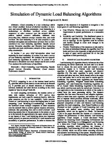
Figure 1. Scatternet Structure A Routing Vector Method (RVM) [7] constructs a routing path for a pair of Bluetooth devices that based on flooding scheme. Although, RVM utilizes all available relays that creates scheduling overhead but it does not consider traffic load that slow down system. As shown in Fig. 2(a) where five piconets exists and two relays r1 and r6 are connecting different piconets. It can observe that only r1 can provide connective among all the piconets, but RVM utilize both the relays. The RVM problem was solved through LORP, as shown in Fig. 2(a) the original scatternet. LORP performs relay reduction and disjoint routes construction for scatternet in distributed manner. LORP performs relay reduction and allows only higher degree of relay that
increases load on the relay. LORP does not consider traffic load in network that slow downs system performance. Fig. 2(b) shows scatternet structure after applying LORP, as r1 has higher degree so it connects all the five piconets therefore relay r6 changes his role and acts as a slave. A large number of traffic passes through the r1 that includes link-1: s1→ m1→ r1→m2 →s2, link-2: s2→ m2→ r1 →m5→ s5 and link-3: s3→ m3→ r1→ m4→ s4, the links are shown above the each arrow in Fig 2(b). It can be analyzed that r1 is always used that is a bottleneck point in the scatternet and it reduces network lifetime.
3. DYNAMIC LOAD BALANCING A relay transmits its information clock offset, BD_Addr and its degree to his masters. As shown in Fig. 2(a) r6 was a pure slave in P4, when it connects m3 and m1 it transmits its new information to all the connected masters. The master node builds a Relay Connection Table (RCT) as shown in Table. 1. When a master gets relay information it adds in the RCT, where 1 shows the connection between masters. According to LORP lower degree relay node breaks his link from all the piconets and participates as slave in a piconet where numbers of nodes are least. After applying LORP Fig. 2(b) shows that r6 role has changed to slave. In the DLB each master maintains relay information and considers lower degree of relay node as BR. A RCT is maintained by master m3 has shown in Table. 1, as r6 has assigned the BR role, because its degree is lower. The DLB does not remove lower degree relay information unlike LORP. Backup relay is basically used to share traffic load of current relay, master keeps BR information as a park node. Once, a master has BR information so it does not need to start from inquiry and inquiry scan procedure. According to Bluetooth specification this is most energy and time consuming process. When master gets the overload information from relay, it tries to resynchronize the backup relay to share the load. Table 1. Master Relay Connection Table Master / Relay Id r1 r6
Figure 2(a). Scatternet before relay reduction
m1
m2
m3
m4
m5
Role
1 1
1 Ø
1 1
1 1
1 Ø
r br
If multiple links pass through a single relay that create bottleneck in the network. The relay monitors traffic pattern, each relay maintains Flow Analysis Matrix (FAM), and it is a square matrix. As the distributed heavy traffic flow passes through relay r1 shown in Fig 2(b). A relay is always involves in the intre-piconet communication, thus the traffic among the different piconets can be easily determined by relay device. The FAM is maintained by r1 shown in Table.2, where r1 records the traffic among five piconets. Table. 2 shows the flow of traffic that passes through r1, the total upload (sends to master) and download (receives from master) traffic has recorded by r1 in FAM. The upload traffic (UT) is recorded in row whereas download traffic (DT) is recorded in column, UT of m2 is 28 and DT is 18. Total load of traffic (TLT) can be calculated through E.q. (1), as a relay can support maximum 7 piconets therefore value of n is less than eight. The values of FAM is reset 0 after every 20 cycles. Each relay switch in a cycle fashion in all the connected piconets, the cycle time depends on bridging policy. ∑
∑
1 , Figure 2(b). Scatternet after relay reduction In this paper we propose two technique firstly, a dynamic configuration approach to the backup relay. Secondly, a Dynamic Load Balancing (DLB) technique to avoiding bottleneck that reduces delay, packet loss moreover, it improves throughput and network lifetime. The next section describes complete process of DLB by selecting an appropriate device to share the traffic load.
1, 2, … ,
8
RVM [7] and LORP [6] are used as the base protocols for proposed technique because these two protocols have special relation with proposed work. According to RVM, a source node broadcasts route SEARCH packet on receiving at destination device considers only the first route SEARCH packet. The destination node unicasts a REPLY packet to the source node, route reply packet is in reverse order of SEARCH packet. Fig. 2(b) shows source (s3) node in P3 sends a route search packet for destination (s4) in P4. According to RVM the final routing path is
constructed as (s3 → m3 → r1 → m4 → s4). When r1 gets route reply packet is also includes its degree and the traffic load. On receiving route reply packet m3 finds total delay (TD) and cycle time of r1 through E.q. (2). The degree of master is multiplied by sum of synchronization and service time plus total traffic load on the relay. The TD is compared with θ, if delay is greater than θ master finds the BR. The θ value is fixed in our case that is 1sec; it gives the maximum throughput and reduces delay. The BR activation depends on the degree (D) of relay and traffic load that forwards through relay. Each master also maintains internal FAM and it calculates total loads of BR. If the BR is not under heavy load then master sends page (activation) message to BR. Once the BR activation operation completes master removes the last relay address from route REPLY packet and puts the BR address and forward the packet to next hop. Each relay and master repeats the same steps till the end of route REPLY packet. In above given case S3 will get route reply packet as (s4 → m4 → r6 → m3 → s3). The master of P3 will replace the r1 with r6 because the total delay through e.q. 2 becomes grater than θ. The service time depends on bridging algorithm; we used MDRP as a bridge algorithm. As r6 is activated as a BR, so the new topology is shown in Fig. 4. Through activation of r6, s3 and s4 can communicate simultaneously; r6 shares the r1 traffic load and avoids the bottleneck in the network.
• • •
Step 4: Once master connects the backup relay it replaces the relay address with BR address and forwards to the next hop. Step 5: At the end when source node gets the route reply packet it start transmission. Step 6: When the transmission ends the master breaks BR link and BR returns to original state as slave.
TD =D X (Synchronization_Time+ Service_Time) + TLT (2) Using an example, operation of BR is illustrated through Fig. 2(b), where s1 is the source node in P1 and sends a route search packet for destination node s2 in P2. The source node s1 transmits in time slot t1 to m1 and m1 forwards to r1 in t2. The time slot t3 is used for synchronization for r1 and m2. The packet is forward form r1 to m2 in t4 and finally it reaches to destination s2 at t5. At the same time in t1 through s3 transmits for s4 however, m3 can not forward due to unavailability of r1. As r1 joins m3 when it completes its task in P3 at t6, then m3 becomes able to forward the packet in t7 thus the total delay of m3 becomes 6 slots. After applying the DLB technique both the packets are forward simultaneously and traffic load of r1 has shard with r6. As shown the transmission from s1 to s2 {t1: s1 → m1, t2: m1 → r1, t3: r1 → m2, t4: m2 → s2} and s3 to s4 {t1: s3 → m3, t2: m3 → r6, t3: r6 → m4, t4: m4 → s4}. It can be analyzed that r6 avoids the bottleneck and increases network lifetime. Table 2. The Flow Analysis Matrix (FAM) Id m1 m2 m3 m4 m5
m1 0 18 42 26 35
m2 28 0 0 0 0
m3 0 0 0 0 0
m4 43 0 0 0 0
m5 35 0 0 0 0
The proposed technique follows the following steps to enable backup relay. Fig. 2(b) shows original topology and after applying DLB new topology is shown in Fig. 4: • • •
Step 1: A relay device records incoming and outgoing traffic in FAM. Step 2: When relay receives route reply packet it adds its traffic load plus degree and forwards to next piconet master. Step 3: When master receives route reply packet from relay it computes total delay, if it is greater then θ master checks for the BR.
Figure 4. Scatternet structure after applying DLB
In the next section, we show results comparison and improvements of proposed technique.
4. PERFORMANCE STUDY In this section we analyze the performance of DLB and compare with standard Bluetooth protocols such as RVM [7] and LORP [6]. The simulation is performed by using UCBT [19] that is and extension of NS-2 [20] for Bluetooth. UCBT is one of Bluetooth simulator that offers rich environment for simulation at different Bluetooth layers whereas, NS-2 is a discrete event simulation environment based on C++. Different parameters [21] are used to investigate the performance of proposed technique, as listed in Table. 3. The simulation space size was set 120 m x 120 m and nodes were deployed randomly varied from 20 to 100, to get the network performance under different loads. A node location, BD_Addr, traffic and internal clock is randomly generated, and transmission range of each node is 10m. Although, DH5 packet takes long time but it gives high throughput. Table 3 shows the performance metrics of the simulation. The Fig. 2(b) shows initial scatternet while, Fig. 4 shows new topology of network after DLB. Table 3. Simulation parameters Parameter Number of nodes Network size Radio propagation range Traffic model Mobility Energy consumption Packet type Pairs of source and destination
Value 20 ≤ N ≤ 100 120 m x 120 m 10m CBR No 0.0763 x 10⁻⁶ J/bit DH5 40
Average Delay (sec)
Transmission delay refers the time required from source to destination, different factors affects delay i.e. bandwidth, queue size, processing and propagation time etc. We analyze that load on a relays increases network delay, due to unnecessary relays utilization of RVM has the highest delay. If unnecessary relays exist in network and do not participate in the scatternet communication that also increases scheduling overhead. Although, RVM utilize all relays but it does not consider traffic load thus, new link also follows the overloaded relay node. On the other hand, LORP performs relay reduction so one relay participates in multiple piconets and number of routes follows the same relay. The proposed technique keeps information about BR, when delay increases due to relay it activates a BR that reduces delay. Fig. 5 shows delay of DLB is almost half comparative RVM and LORP.
RVM
100 90 80 70 60 50 40 30 20 10 0 20
LORP
40 60 80 Number of Nodes
DLB
100
Figure 5. Average Delay vs. Number of Nodes
Average Packet Loss Rate
4.1 Average Transmission Delay
RVM
9.0 8.0 7.0 6.0 5.0 4.0 3.0 2.0 1.0 0.0
20
DLB
40 60 80 Number of Nodes
100
Figure 6. Average Packet Loss Rate vs. Number of Nodes
4.3 Throughput Throughput refers to average rate of successful messages delivered or successful data bytes received by a node in per unit time. As shown in Fig 2(b) LORP creates the congestion after relay reduction and RVM also follows the same route. When large number of routes follow a single relay, due to unavailability of relay all other the masters are blocked only one pair can communicate at the same time. In the proposed technique not only monitoring congestion, same when there is no need of a relay the link is broken and useless time for synchronization is saved. Therefore, the DLB is more effective than RVM and LORP in term of throughput. DLB monitors the traffic load if load increases, it activates the BR as shown in Fig. 4 that improves overall throughput of the system. Fig. 7 shows when number of nodes increase more than 40 the LORP performs well comparative RVM because LORP needs some extra time to define the relay role. The DLB throughput is approximately double comparative LORP and RVM.
Throughput (kbps)
4.2 Packet Loss Rate When one or more packets fail to reach destination across the network that is called packet loss. In this subsection we describe the packet loss is reduced through the proposed technique. The piconet communication is depending on the master whereas, the scatternet performance depends a lot on the relay. A relay shares its time in the network, relay and master both depends on each other availability. As a relay node needs more energy because it participates in multiple piconets. RVM and LORP both are neglecting traffic load when heavy traffic passes through relay node it reduces lifetime of network. There are many chances that a relay node dies due to insufficient power, when a relay node dies it affects all the inter-piconet communication. Also when queue overflows packet loss rate increases, DLB controls packet loss rate by monitoring traffic flow and reduces bottleneck. The DLB activates backup relay that shares load and avoids congestion which ultimately reduce packet loss. After enabling BR when a relay dies it does not affects large number of links because the traffic load has shared through BR. It can be observed when number of nodes increased more than 60 RVM increases packet loss due to unnecessary relay flooding. The comparison of packet loss is shown in Fig. 6 by different protocols. It is observed that DCC has less packet loss, because DLB monitors traffic load and avoids bottleneck therefore its packet loss is less comparative RVM and LORP.
LORP
RVM
40 36 32 28 24 20 16 12 8 4 0 20
LORP
DLB
40 60 80 Number of nodes
100
Figure 7. Through vs. Number of Nodes
4.4 Network Lifetime The period of time during network remains connected is known as network lifetime, Fig. 8 shows the comparison of RVM, LORP and DLB lifetime. The lifetime of a network depends on the service time of each node as a relay node participates in multiple piconets so it decreases its battery frequently. RVM and LORP do not consider traffic load that pass through the relay. LORP only utilize higher degree selected relay due to heavy traffic relay power reduces quickly that decreases network lifetime. LORP follows the same route as RVM does, but due to less member of
Average Down-link by Relay Node
relay its lifetime is comparative better than RVM. It can be analyzed, when numbers of nodes increase the average down-link also increases due to large number of relays. On the other hand, DLB under intensive load enables backup relay and divide the traffic load moreover, DLB reduces the unnecessary relays that increases the lifetime proposed technique.
9.0 8.0 7.0 6.0 5.0 4.0 3.0 2.0 1.0 0.0
RVM
LORP
DLB
[7]
[8]
[9] [10] [11]
20
40 60 80 Number of Nodes
100
Figure 8. Network Lifetime vs. Number of Nodes
5. CONCLUSIONS The paper proposed an effective Dynamic Load Balancing technique to overcome the transmission congestion problem and improve the performance in Bluetooth WPANs. Although, RVM utilize maximum relays but still it do not consider traffic load. In contrary, LORP removes lower degree of relays and traffic load increases on higher degree of relay. Hence, there was a chance to improve system performance by introducing a flexible technique. Therefore, DLB is proposed to avoid bottleneck. The proposed technique shares traffic loads of a relay with the help of master therefore, multiple transmissions can made possible simultaneously. The BR reduces traffic load without affecting scatternet connection. Once the communication ends master node breaks BR link to avoid delay and BR goes to its original state. The simulation results show that proposed technique works well in terms of delay, throughput and packet loss comparative RVM and LORP. These applications can be used in earthquake, supermarkets, shopping malls and mobile e-commerce scenarios.
[12] [13]
[14] [15] [16]
[17] [18]
6. REFERENCE [1] Wireless PAN medium access control MAC and physical layer PHY specification. IEEE standard 802.15, IEEE, New York, NY, 2002. [2] Bluetooth SIG, Bluetooth Specification v2.0. 2004. [3] Chih-Yung Chang a, Kuei-Ping Shih a, Chung-Hsien Hsu b, Hung-Chang Chen., “A location-aware multicasting protocol for Bluetooth Location Networks“, in: Wireless Personal Communications, Vol 177 , Issue 15, pp. 3161-3177, 2007. [4] Csaba Kiss Kallo , Carla-Fabiana Chiasserini, Sewook Jung, Mauro Brunato, Mario Gerla., “Hop count based optimization of Bluetooth scatternets”. In: Ad Hoc Network Vol 5, Issue 3, pp. 340-359, 2007. [5] Vojislav B. Misic and Jelena Misic1., “Polling and Bridge Scheduling Algorithms in Bluetooth” technical report TR 03/04 Department of Computer Science, University of Manitoba Winnipeg, Manitoba, Canada R3T 2N2 September 2003. [6] Gwo-Jong Yua, Chih-Yung Changb, Kuei-Ping Shihb, ShihChieh Leeb., ”Relay reduction and disjoint routes construction
[19] [20] [21]
for scatternet over Bluetooth radio system”, in: Journal of Network and Computer Applications, Vol 30, pp. 728–749, 2007. P. Bhagwat, A. Segall., “A Routing Vector Method (RVM) for routing in Bluetooth scatternets”, Mobile Multimedia Communications, in proc. of IEEE International Workshop, pp. 375-379, 1999. Chih-Yung Chang, Prasan Kumar Sahoo, Shih-Chieh Le.,e., “LARP: A Novel Routing Protocol for the Bluetooth Scatternet”, in: Wireless and Optical Communications Networks, Second IFIP International Conference on, pp. 5660, 2005. F.J. Gonzalez-Castano, J. Garcia-Reinoso,”Survivable Bluetooth Location Networks”, in Proc. of IEEE ICC, Vol 2, pp. 1014-1018, 15 May 2003. A. Darling”Waiting for the m-commerce explosion”, in Telecommunication Internationa, pp. 34-39, 2001. Salonidis, T. Bhagwat, P. Tassiulas, L. LaMaire, R., “Distributed topology construction of Bluetooth wireless personal area networks”, in: IEEE Selected Areas in Communications, Vol 23, Issue: 3, pp. 633- 643, 2005. F.J. Gonzalez-Castano, J. Garcia-Reinoso., “Bluetooth location networks”, in: proc. of IEEE Global Telecommunications, 2005. Prasan Kumar Sahooa, Chih-Yung Changb, Sheng-Wen Changb., “Novel route maintenance protocols for the Bluetooth ad hoc network with mobility”, in: Journal of NETWORK and Computer Applicaiotns, 2007. Perkins, C., & Bhagwat, P., “Destination sequenced distance vector routing for mobile computers”, In Proc. ACM SIGCOMM, Vol 24, Issue 4, pp. 234 – 244, 1994. Perkins, C., & Royer, E., “Ad-hoc on-demand distance vector routing”, in Proc. Of IEEE Workshop on Mobile Computing Systems and Applications, pp. 90-100, 1999. Yang, C.-H., & Ruan, J., ”On-demand routing for Bluetooth Scatternets subject to device mobility”, in: proc. of the 19th International Conference on Advanced Information Networking and Applications, pp. 363- 366, 2005 . C.C. Chiang, M. Gerla., “On-demand multicast in mobile wireless networks” in: proc. of the 6th International Conference on Network Protocols, ICNP, pp. 262–270, 1998. J. Misic and V. B. Misic., “Bridges of Bluetooth county: topologies, scheduling, and performance”, in: IEEE Journal on Special Areas in Communications – Wireless, Vol 21, Issue: 2, pp. 240- 258, Feb 2003. University of Cinicinnati Bluetooth simulator (UCBT), http://www.ececs.uc.edu/_cdmc/ucbt/, June 2010. The Network Simulator ns-2, http://www.isi.edu/ nsnam/ns/ns-build.html, June 2010. O. Al-Jarrah, O Megdadi “Enhanced AODV routing protocol for Bluetooth scatternet” in: Computer and Electrical Engineering, Vol. 35, Issue 1, pp. 197-208, 2009.