S. R. Duncan is with the Department of Engineering Science, University of. Oxford, Oxford OX1 .... DUNCAN et al.: DYNAMIC ..... Wesley, 1995. [11] A. Hansson ...
IEEE TRANSACTIONS ON CONTROL SYSTEMS TECHNOLOGY, VOL. 8, NO. 4, JULY 2000
667
Dynamic Modeling of Cross-Directional Actuators: Implications for Control Stephen R. Duncan, Member, IEEE, Julian M. Allwood, Will P. Heath, and Kenneth W. Corscadden
Abstract—Actuators that bend slice lips are commonly used in cross-directional (CD) control systems for paper making and plastic film extrusion. A dynamic model of these actuators is developed which is used to investigate their spatial modes and dynamic responses. The model shows that both the shape and the amplitude of the spatial response depend upon the stiffness of the slice lip. The design of most practical CD control systems is simplified by assuming that the spatial and dynamic responses are separable in the sense that each of the spatial modes has the same dynamics. The validity of this assumption is examined and it is shown that subject to conditions that are likely to be satisfied in practice, the responses can be taken as separable. The model is verified using data from plastic film extrusion line and the consequences of separability for the design of CD control systems are discussed. Index Terms—Actuators, control systems, distributed parameter systems, metals industry, modeling, plastic films, pulp and paper industry.
of actuators in the array can vary from two (for example, when using jacks to adjust the amount of work roll bending for controlling shape variations in a cold rolling mill) up to one hundred (for controlling basis weight variations on a paper machine by bending the slice lip using the slice lip screws). The design of controllers for processes with large numbers of actuators is challenging due to the very high dimensionality of the system. In order to make the control design manageable, it is usual to reduce the dimension of the system by assuming that the spatial (or CD) and dynamic responses of the actuators are separable. denotes CD position, with being the width of the If will be used to describe the combined effect sheet, then of the actuators at a given CD location and time . Applying , which, a Laplace transform to the time variable gives under the assumption of separability, can be expressed as the product of a dynamic term and the combined spatial response of the actuators
I. INTRODUCTION (1)
T
HE DEMAND for high-quality finished products from industrial web processes such as paper making, metal rolling, plastic film extrusion and coating, means that attention is now being paid to variations in properties over the whole surface of the sheet. As a result, automatic cross-directional (CD) control systems are now commonplace in many of these industries and are used to regulate a range of properties including: • basis weight, moisture and caliper (thickness) variations in paper [1]; • gauge (thickness) profile in hot rolling and shape (residual tension) variations in cold rolling of metals [2]; • thickness variations in plastic film extrusion [3]; • coat weight and coat thickness variations in coating processes [4], [5]. In each case, the variations in sheet properties are controlled by adjusting the set points of an array of actuators. The number Manuscript received October 14, 1998. Recommendd by Associate Editor, G. Dumont. This work was supported by the Engineering and Physical Science Research Council of the United Kingdom under Grants GR/J65334 and GR/K04378, an Engineering Technology Foresight Award from the Royal Academy of Engineering and a Visiting Fellowship from the Advanced Systems Institute of British Columbia, Canada. S. R. Duncan is with the Department of Engineering Science, University of Oxford, Oxford OX1 3PJ, U.K. J. M. Allwood is with the Department of Mechanical Engineering, Imperial College of Science, Technology and Medicine, London SW7 2AZ, U.K. W. P. Heath is with the Centre for Integrated Dynamics and Control, University of Newcastle, Callaghan, NSW 2308, Australia. K. W. Corscadden is with JH Instrumentation Ltd., Larkfield, Aylesford, Kent ME20 6SE, U.K. Publisher Item Identifier S 1063-6536(00)05754-7.
is a scalar transfer function describing the dynamics, are the Laplace transforms of the input signals applied to the actuators and are the shapes of the spatial change produced by each actuator. It is assumed that each actuator has the same dynamic response. Subject to mild conditions, which are readily satisfied in practice, the individual spatial response can be expressed in terms of a basis function expansion
Here
(2) where
are a set of basis functions that are orthonormal on . Using this expression in (1) gives (3)
, means that The presence of the scalar transfer function, the assumption of separability requires that each of the spatial modes has the same dynamic response. Also, from (1), separability implies that when a change is applied to the actuators, the shape of the spatial response remains the same throughout the transient response. These are severe restrictions and in general, there is no reason to assume that the separable structure is valid. This paper examines the assumption of separability by modeling the response of a class of CD actuators which bend a
1063–6536/00$10.00 © 2000 IEEE
668
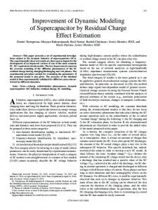
Fig. 1.
IEEE TRANSACTIONS ON CONTROL SYSTEMS TECHNOLOGY, VOL. 8, NO. 4, JULY 2000
Section of part of headbox slice showing pulp between flexible upper slice lip and rigid lower lip, together with slice lip screws (not to scale).
lip slice. The steady-state response of these actuators has been addressed by a number of authors, including [6]–[8], but in this paper, the analysis of [7] is extended by considering the full dynamic partial differential equation (PDE), rather than the steady-state version. It is shown that for this class of actuators, the assumption of separability is justified provided that a set of conditions associated with the stiffness of the beam and the supporting screws are satisfied. Section II describes the slice lip actuators used in paper making and plastic film extrusion. Section III models the response of these actuators and compares the response of the model with results from a plastic film extrusion line. Section IV concludes the paper. II. SLICE LIP ACTUATORS Slice lip actuators are used for regulating basis weight (or density) variations in paper making and thickness variations in plastic film extrusion processes. In paper making, the slice lip forms part of the headbox whose primary purpose is to convert the flow of stock (diluted pulp) from a round pipe to a narrow rectangular flow that is then projected onto the forming table [9]. Subsequent processes remove the water to create the sheet of paper. The purpose of the slice lip is to accelerate the pulp and to deliver a stable jet through a well-defined rectangular opening. The size of the width opening is adjusted by a series of screws attached to the slice lip at points across the machine, as shown in Fig. 1. Typically, the separation between the screws is less than 100 mm and on large machines there may be between 50 and 100 screws. If a screw is extended, this causes the lip to flex, locally narrowing the gap and redistributing pulp in the cross direction away from this point. When the water is removed from the stock by the downstream processing, this has the effect of reducing the density (basis weight) of the pulp in this region. By adjusting the length of all the screws, the slice lip can be bent (within limits) to provide the required CD basis weight profile. Originally the screws were extended and retracted manually, but modern systems either use thermal expansion, via heated bolts,
or motor drives to provide the required degree of bend to the slice lip [1]. In plastic film extrusion, the slot die is used to convert a flow of molten polymer to a thin, uniform curtain which is formed into a film on a chilled casting roll [3]. CD variations in the thickness of film can be adjusted by locally bending the die lip to change the width of the gap through which the polymer is extruded. As in the case of paper making, the die lip is bent by changing the length of the lip screws and as the die gap is narrowed, molten polymer is redistributed away from this point, causing a reduction in the thickness. Both thermal expansion and motor drives are used to move the screws. III. MODELING THE DYNAMIC RESPONSE OF A SLICE LIP ACTUATOR Following [7], it is assumed that the slice lip can be modeled equally spaced simple as a slender beam supported by supports, where the supports correspond to the slice lip screws. It is assumed that the screws only apply loads normal to the slice, so that there is no tangential component to the load, and that they are coupled through frictionless joints which impart no direct moment. If the beam is thin relative to its length, then the loads applied to the beam are sufficiently small so that the magnitude of the deflection is much less than the beam dimension. The , defined on , under a load, , deflection, is closely approximated by a linear Euler–Bernoulli model [10] (4) where denotes Young’s modulus; is the second moment of area of the beam; is the density of the beam; its cross-sectional area. The second term in (4) describes the effect of viscous damping on the movement of the slice lip with being used to denote the damping coefficient. It is likely that there will be other damping
DUNCAN et al.: DYNAMIC MODELING OF CROSS-DIRECTIONAL ACTUATORS: IMPLICATIONS FOR CONTROL
effects acting on the lip [10], but given that lip is in contact with the pulp flowing through the slice, it is reasonable to assume that the viscous effect is the dominant damping mechanism. , consists of two comThe normal load on the beam, , due to the ponents: the distributed force per unit length, pressure of the pulp on the slice lip, and the balancing forces applied by the individual screws, so that
(5)
denotes the force applied where to the th screw and is the separation between the screws, so . The individual forces applied by the screws that can be decomposed further as
669
The solution to this equation is separable and the deflection takes the form [10] (11) is a set of orthogonal basis functions describing the where describe the dynamics spatial modes of the deflection and into (10) of these modes. Substituting this expression for and rearranging gives a series of expressions of the form (12) each of which can be written as two separate equations (13)
(6) is the steady-state force that is applied to the th screw where and denotes a deviation from this in order to balance steady-state force. It is assumed that the pressure exerted by the pulp on the lip is not affected by small variations in the shape and are invariant to small changes of the lip, so that . in To model the effect of a change in the slice lip gap due to a movement of one or more or the screws, express the deflection, , as
(14) . If the beam is pinned by the screws at the where two ends, this imposes boundary conditions on the PDE and the allowable modes of the deflection are given by [10] (15) with
(7) (16) represents the steady-state deflection when all of where denotes the screws are at their nominal positions and the deviation from this steady state. The steady-state deflection satisfies [7]
Applying the separable solution in (11) to the inhomogeneous equation in (9) gives
(8) and because the system is assumed to be linear, the PDE deis obtained by substituting (8) into (4), giving scribing
(9) For simplicity, movements to the screws at either end of the and ) will not be considered, beam (i.e., for which means that these screws can be considered as simple supports for the beam. The analysis can be extended to allow for changes to the positions of these screws by including a linear and slope to the deflection of the form imposing conditions of force and moment equilibrium, as in [7]. In the absence of any forcing terms, the deflection of the beam is described by the homogeneous portion of the PDE in (9) (10)
(17) where the summation on the right-hand side is limited to the , because the end screws are taken to be range fixed. , gives Using (13) and exploiting the orthogonality of (18) and are zero, Assuming that the initial conditions on a Laplace transform can be applied to the time variable, leading to (19)
670
IEEE TRANSACTIONS ON CONTROL SYSTEMS TECHNOLOGY, VOL. 8, NO. 4, JULY 2000
where denotes the Laplace transform of the force applied to the th screw. The two components of the solution can be combined using (11) and (15)
(20) denotes the result of applying a Laplace transwhere and form to the time variable of (21) If a unit step change in the force is applied to the th screw while the forces on the other screws remain fixed, then applying the final value theorem, the steady-state deflection of the beam is (22)
and
is a diagonal matrix with entries . The aim of this paper is to derive a dynamic model of the lip deflection by extending the steady-state version considered in [7]. Unlike the steady-state case, it is not possible to deduce the dynamic forces directly from the model in (25), primarily because it requires the inversion of the transfer function which is strictly proper. This is a reflection of the fact that a without incurring infinite step change cannot be applied to forces. In reality, the slice lip screws are not rigid, but instead they act as stiff springs. If the screws are straight rods, normal to the slice lip, then when the actuators move one end of the rod, the other end, where the screw meets the slice lip, does not experience the same displacement. Modeling the screws as linear springs, the forces generated by the screws are proportional to the relative movement between the two ends of each rod, so that (27) is a vector containing the position of the end where of the rod attached to the actuator and is the spring constant gives of the screw. Using (25) to substitute for (28)
This response can be approximated by truncating the summation term is proporat a finite number of terms. Because the , it is only necessary to include a few terms in the tional to expansion in order to obtain a good approximation to the analytical solution of the steady-state PDE [7] (23) and represents the singularity function where whose value is zero unless the argument is greater than zero. So far, the deflection of the beam in (20) has been expressed in terms of the forces applied to each screw, rather than their positions. It is assumed that the screws are attached to the beam which constrains the deflection of the beam at the location of . If a force is applied to the screws, so that move a single screw, then the other screws must generate forces to ensure that the constraints are satisfied at . This is equivalent to requiring that
which can be rearranged to (29) This describes the forces generated in the screw as its end is moved by the actuator and can be used in conjunction with (19) to model the response of the lip to a step input. It is instructive to consider the screws as a form of inherent feedback mechanism which generates the forces required to make the deflection at the points where the screws are attached to the beam, match the changes applied to the end of the screws (as illustrated in Fig. 2). The screws act as a set of high gain proportional terms in the feedback loop, where the gains correspond to the spring constant of the screws . is chosen to be an integer multiple of , then from If , so the (26), the structure of means that can be rearranged to expression for
(30) (24) is the Laplace transform of the position of the th where terms, then (24) actuator. If the first summation is limited to can be written as (25) and are vectors containing the where Laplace transforms of the forces and the positions of the indiis a matrix whose th element vidual actuators. is (26)
where
is a diagonal matrix with entries (31)
is A similar expression can be derived for the case where , by taking the singular value not an integer multiple of decomposition of . Using (19), the Laplace transform of the dynamics associated with each spatial mode can be written as (32) is a vector whose elements describe the where dynamics of the individual modes. The steady-state magnitude
DUNCAN et al.: DYNAMIC MODELING OF CROSS-DIRECTIONAL ACTUATORS: IMPLICATIONS FOR CONTROL
671
Fig. 2. Block diagram of inherent feedback mechanism that generates forces, F (s), to match the movement of the screw at the slice lip, P (s) to the movement at the actuator, P (s).
Fig. 3. Steady-state deflection of a unit length slice lip with 11 screws with a unit force applied to the fourth screw, when the spring constant, k , is high (solid), medium (dashed), and low (dotted).
of each mode in response to a step change in the position of the th screw is given by
(33) is a vector containing the response of the where is a vector of zeros except for individual modes and and are both the th element, which is set to unity. th elements are diagonal matrices whose (34) Incorporating the steady-state values of each mode into equation , the steady-state deflection of the (11) gives beam in response to a step change in the position of the th screw. In the limit where the screw becomes infinitely stiff, so , the resultant response agrees with the shape of the that steady-state response given in [7]. Fig. 3 shows the shape of the steady-state step response for finite values of . The solid line gives the response when is large and approaches the response in [7]. The other curves show the response as the screws become less stiff, or equivalently as the slice lip becomes stiffer, and it can be seen that
• • • •
width of the CD responses increases; magnitude of the response reduces; response becomes less oscillatory; peak of the spatial response moves away from the location of the screw toward the center of the lip. All of these effects are observed in practice for stiff slice lips, particularly on machines producing heavy-weight papers or board [1], [11]. It has usually been assumed that these effects are caused by the flow of pulp on the wire, and while it is likely that the flow is the dominant effect, the analysis presented here suggests that the variation in the shape of the lip is also makes a contribution to the overall shape of the response. The shape of the steady-state response is determined primarily by the relative stiffness of the screws and the slice lip, but the dynamic response depends on , the viscous damping. From (32), the dynamic behavior of each mode consists of two components; the inherent feedback mechanism, , representing the forces generated by the screws , the response of each in response to the step change, and mode to these forces. In practice, the screws are stiff, so the loop gain of the inherent feedback is high and the response of this component is fast. As a result, the dynamic response of the lip is dominated by the response of the lip to the varying forces applied by the screws. The response of each mode to a change , as given in (21). in force is determined by the elements of
672
IEEE TRANSACTIONS ON CONTROL SYSTEMS TECHNOLOGY, VOL. 8, NO. 4, JULY 2000
(a)
(a)
(b)
(b)
Fig. 4. (a) Dynamic deflection of a unit length slice lip with 11 screws when a step change is applied to the end of the fourth screw. (b) Dynamic behavior of first (solid), third (dashed), fifth (dash-dotted), and seventh (dotted) spatial modes.
Fig. 5. (a) Dynamic deflection of unit a length slice lip with 11 screws when the change in position to the fourth screw is applied through a first-order transfer function. (b) Dynamic behavior of first (solid), third (dashed), fifth (dash-dotted) and seventh (dotted) spatial modes.
The magnitude of the response of each term is proportional to which from the expression for in (16) is proportional to , so it is likely that the dynamic response will be dominated by response of the low-order modes. Provided that the viscous for these modes, damping is sufficiently large, so that then each mode will have virtually the same overdamped response and as a result, the overall response can be regarded as separable. This is illustrated in Fig. 4 which plots the dynamic deflection of the beam along with the response of a selection of the low-order modes. It can be seen that after a very short initial transient, associated with the response of the inherent feedback mechanism, the shape of the response remains almost constant throughout, indicating that the response is close to being separable. This is confirmed by Fig. 4(b) which shows that the modes have very similar overdamped responses. In practical implementations, the position of the end of a screw is adjusted by applying an input to the screw’s actuator (usually a stepper motor or a heating element) and the actuators do not respond sufficiently quickly to apply a step change to the position of the screws. The more realistic situation is shown in Fig. 5(a) where the step change is applied through a transfer function describing the dynamics of the actuators themselves, so that
where is the Laplace transform of the input signal apis the transfer function of the replied to the th screw and sponse of the actuator. The dynamic response of the actuator has been taken to be first order, where the time constant is chosen so that the actuator dynamics are slower than the dynamics of the slice lip (determined by the damping on the lip). It can be seen that the shape of the spatial response remains constant throughout and Fig. 5(b) shows that there is no appreciable difference between the dynamic response of the modes. The slow response of the screws is often used as justification for the separability of the response, but the preceding analysis has shown that the response will be separable even when a step change is applied to the position of the screw.
(35)
IV. COMPARISON WITH RESULTS FROM PLANT TRIAL The model has used a number of assumptions which in practice are only approximations. In particular, the slice lip is not a simple beam as it is connected to the rest of the headbox at a number of positions along its length. In addition, the screws do not act as simple supports as they provide a distributed force on the beam rather than a point force, and it is likely that they will also apply a moment and a tangential force. Although the model that has been produced is idealized, its validity is demonstrated in Fig. 6(a), which shows the change in thickness due to a change in position of a single slice screw on a plastic film line
DUNCAN et al.: DYNAMIC MODELING OF CROSS-DIRECTIONAL ACTUATORS: IMPLICATIONS FOR CONTROL
(a)
673
extrusion line, the cross-directional flow is much less once the polymer has left the die lip, so the change in CD thickness profile matches the profile of the slice lip more closely, as can be seen from Fig. 6(a). Since the allowable spatial modes of the deflection in (15) are sinewaves, this suggests that a Fourier series is the most natural basis function expansion for decomposing the response of the CD actuators, rather than the Gram polynomials used in [7], [14]–[16]. This is a consequence of the boundary conditions imposed by assuming that the ends of the slice lip are pinned. However, as discussed above, in practice the shape of the spatial response on the sheet is distorted after it leaves the slice lip and in many processes, the edges of the sheet are trimmed before the variations are measured. Under these circumstances, the boundary conditions on the bending of the beam no longer apply to the variations observed on the sheet and it is equally valid to use other basis function expansions, such as Gram polynomials, to analyze the variations. V. CONCLUSIONS
(b) Fig. 6. (a) Change in thickness observed on a section of film from a plastic film extrusion line when a step change is applied to the setting of a single screw. (b) Dynamic behavior of first (solid), third (dashed), fifth (dash-dotted) and seventh (dotted) spatial modes.
[12]. The plant was producing a polyethylene film of width 2 m at a haul-off speed of 70 m/min. Unm and thickness like a paper machine, on plastic film lines, it is common to bend both the slice lips on both sides of the extrusion die. On this line, a total of 73 thermal expansion bolts were divided between the two lips, with each bolt having a time constant of around 11 min. Data was collected using a scanning gauge with a scan time of 55 s. The data has been preprocessed to compensate for the known filtering within the gauge and to remove the high-frequency components of the noise [13], [12]. The observed response closely matches the response in Fig. 6(a) that was generated by the model. Fig. 6(b) shows that the spatial modes of this response have very similar dynamics, indicating that the response is separable. The model that has been developed in this section describes only the effect on the slice lip that results from a change in the position of the lip screws. In practice, the response that is observed at the gauge depends upon the effect of the bending of the slice lip on the flow of pulp or polymer through the slice. On a paper machine, if the slice lip is bent to restrict the flow of pulp, then this sets up waves which spread across the sheet until the pulp reaches the dry line [11]. The shape of the CD basis weight response can therefore be very different from the profile of the slice lip bending, particularly on processes producing heavy-weight papers and boards. By contrast, on a plastic film
This paper has produced a dynamic model of the actuators that adjust CD variations by bending a slice lip. The model has shown that the shape of the steady state spatial response of these actuators is primarily determined by the relative stiffness of the slice lip and the screws. As the lip becomes stiffer, the spatial response of the screws becomes wider and less oscillatory and the center of the response may not occur at the CD location of the screw. It has been shown that provided there is sufficient viscous damping on the slice lip, then the lower order spatial modes have similar dynamic responses and the the overall response of the actuators can be regarded as separable. This aspect was confirmed by comparing the response of the model with the response observed on a plastic film extrusion line. However, separability is a consequence of the inherent feedback mechanism that makes the deflection of the lip match the position of the screws, which constrains the dynamic responses of the modes to be the same. This is a special case and this form of constraint will not necessarily apply for other types of CD actuators. As a result, the dynamic behavior of the modes will be different for these actuators and their responses nonseparable, unless the actuators are moved sufficiently slowly that the magnitude of the dynamics associated with the high-order spatial modes is negligible. The separable form of the actuator response simplifies the design of CD control systems, because the design of the controller dynamics can be reduced to a series of single input–single output (SISO) problems [17], [18]. By contrast, the disturbances that enter the process are usually nonseparable, particularly for the higher order spatial modes [19]. This implies that a system with actuators that have a separable response will be unable to remove these modes. Previous work [14], [20]–[22] has shown that it is natural to consider the controllability of the system in terms of both spatial and dynamic frequencies. The dynamic response of the system is dominated by the speed of the response of the actuators and the transport delay from the actuators to the point of measurement. As a result, there is a large imbalance between the spatial and the dynamic responses [19]. Current developments in actuator technology, such as dilution flow head-
674
IEEE TRANSACTIONS ON CONTROL SYSTEMS TECHNOLOGY, VOL. 8, NO. 4, JULY 2000
boxes [23], are improving the speed of response of the actuators. Coupled with the introduction of arrays of sensors [24]–[27], which allow much faster sampling rates compared to the traditional scanning gauge methods, there is the potential to implement control systems with a wider dynamic bandwidth. This will be particularly beneficial in processes where the quality of the sheet is measured in terms of the variation over relatively small areas of sheet. As the dynamic bandwidth of the system increases, the validity of the assumption of separability will become more critical and it may be necessary to design control algorithms that either do not require this assumption or can accommodate deviations from separability.
REFERENCES [1] K. A. Cutshall, “Cross-Direction Control,” in Paper Machine Operations, 3rd ed. Atlanta, GA: Joint Textbook Committee of the Paper Industry of United States and Canada, 1991, vol. 7, ch. XVIII. [2] G. F. Bryant, Automation of Tandem Mills. London, U.K.: Iron and Steel Institute, 1973. [3] S. Levy and J. F. Carley, Plastics Extrusion Technology Handbook, 2nd ed. New York: Industrial, 1989. [4] R. D. Braatz, M. L. Tyler, M. Morari, F. R. Pranekh, and L. Sartor, “Identification and cross-directional control of coating processes,” AIChE J., vol. 38, pp. 1329–1340, 1992. [5] G. S. Goodwin, S. J. Lee, and A. Carlton, “Application of Kalman filtering to zinc coating mass estimation,” in Proc. 3rd IEEE Conf. Contr. Applicat., Glasgow, U.K., 1994, pp. 1539–1544. [6] R. Balakrishnan and D. McFarlin, “The application of a model of the slicelip as an elastic beam for weight profile control,” in Proc. Tappi Process Contr. Symp., 1985, pp. 105–109. [7] K. Kristinsson and G. A. Dumont, “Cross-directional control of paper machines using Gram polynomials,” Automatica, vol. 32, no. 4, pp. 533–548, 1996. [8] R. M. Tong, “Control of grammage profile on a paper machine,” Ph.D. dissertation, Cambridge Univ., Cambridge, U.K., 1975. [9] R. A. Reese, “Hydraulic Headboxes,” in Paper Machine Operations, 3rd ed. Atlanta, GA: Joint Textbook Committee of the Paper Industry of United States and Canada, 1991, vol. 7, ch. VI. [10] S. S. Rao, Mechanical Vibrations, 3rd ed. Reading, MA: AddisonWesley, 1995. [11] A. Hansson, “CD basis weight control, facts explained and experience gained,” in Proc. Joint TAPPI Process Contr., Elect. Eng. Conf. ISA PUPID 38th Annu. Symp., Vancouver, BC, Canada, 1998, pp. 75–94. [12] A. P. Kjaer, “Modeling, sensing and identification of web-forming processes,” Ph.D. dissertation, UMIST, Manchester, U.K., 1994. [13] T. Nielsen, “Signal processing for web forming processes,” M.Sc. thesis, UMIST, Manchester, U.K., 1995. [14] W. P. Heath, “Orthogonal functions for cross-directional control of web forming processes,” Automatica, vol. 32, no. 2, pp. 183–198, 1995. [15] M. J. Grimble and J. Fotakis, “The design of strip shape control-systems for senzimir mills,” IEEE Trans. Automat. Contr., vol. AC-27, pp. 656–666, 1982. [16] K. W. Corscadden and S. R. Duncan, “A reduced order estimator for closed loop on-line estimation of crossdirectional parameters in a plastic film extrusion process,” Proc. Inst. Elect. Eng. Contr. Theory Applicat., vol. 144, no. 6, pp. 549–558, 1997. [17] S. R. Duncan, “The design of robust cross-directional control systems for paper making,” in Proc. Amer. Contr. Conf., Seattle, WA, 1995, pp. 1800–1805. [18] , “The cross-directional control of web forming processes,” Ph.D. dissertation, Univ. London, London, U.K., 1989. [19] S. R. Duncan, P. E. Wellstead, and M. B. Zarrop, “Actuation, sensing and two-dimensional control algorithms: Fundamental limitations on achievable bandwidths in MD/CD control,” in Proc. Joint TAPPI Process Contr., Eng. Inform. Conf. ISA PUPID 38th Annu. Symp., Vancouver, BC, Canada, 1998, pp. 245–258. [20] S. R. Duncan and G. F. Bryant, “Spatial controllability of cross-directional control systems for web processes,” Automatica, vol. 33, no. 2, pp. 139–153, 1997.
[21] S. R. Duncan, J. M. Allwood, and S. S. Garimella, “The analysis and design of spatial control systems in strip metal rolling,” IEEE Trans. Contr. Syst. Technol., vol. 6, pp. 220–232, 1998. [22] K. W. Corscadden and S. R. Duncan, “The use of basis function expansions to analyze the robustness of cross-directional control,” in Proc. Amer. Contr. Conf., Albuquerque, NM, 1997, pp. 1478–1482. [23] A. Graser, “Advanced cross profile control due to novel profile actuators,” in Proc. Tappi Eng. Conf., Dallas, TX, 1995, pp. 681–686. [24] R. J. Pfeifer, P. Williams, and R. Holmes, “System considerations for a fullsheet imaging system,” in Proc. Joint TAPPI Process Contr., Elect. Eng. Conf. ISA PUPID 38th Annu. Symp., Vancouver, BC, Canada, 1998, pp. 131–144. [25] S. I. Shapiro, R. N. Vyse, and C. Hagart-Alexander, “New wet end weight measurement system opens papermaking optimization opportunities,” in Proc. Joint TAPPI Process Contr., Elect. Eng. Conf. ISA PUPID 38th Annu. Symp., Vancouver, BC, Canada, 1998, pp. 207–214. [26] P. H. Hindle and C. R. R. Smith, “Ultra-fast web thickness and coating measurements with true, two-dimensional control,” in Proc. NIR’94 Conf., Lorne, Australia, 1994. [27] A. P. Kjaer, P. E. Wellstead, and W. P. Heath, “On-line sensing of paper machine wet-end properties: Dry-line detector,” IEEE Trans. Contr. Syst. Technol., vol. 5, pp. 571–585, 1997.
Stephen R. Duncan (M’96) was born in Liverpool, U.K., in 1959. He received the M.A. degree in physics and theoretical physics from Cambridge University, U.K., and the M.Sc. and Ph.D. degrees in control systems from Imperial College, London, U.K. From 1989 to 1993 he was a Director of Greycon Ltd., and from 1993 to 1998 he was with the Control Systems Centre, UMIST, Manchester, U.K., where he was appointed Reader. Since 1998, he has been with the Department of Engineering Science at the University of Oxford, U.K., where he is a Lecturer. His current research interests include the control of industrial processes, distributed parameter systems, and the modeling of the dynamics of epidemics.
Julian M. Allwood was born in Loughborough, U.K. in 1965. He received the M.A. degree in engineering science from Cambridge University, U.K., in 1987 and the Ph.D. degree from Imperial College, London, U.K., in 1993. In 1997 he also received the MBA degree from Imperial College. Having completed a series of short research contracts, he was appointed as a Lecturer in the Department of Mechanical Engineering at Imperial College in January 1997. His current research interests include the fast modeling of metal rolling processes, particularly the evolution of residual stresses through the roll bite, the control of metal rolling processes, contact mechanics, the robotic application of adhesives and the development of manufacturing education in the United Kingdom.
Will P. Heath was born in London, U.K., in 1966. He received the B.A. degree in mathematics from Cambridge University in 1987. He received the M.Sc. and Ph.D. degrees from the Control Systems Centre, UMIST, Manchester, U.K., in 1989 and 1992, respectively, and continued as a Research Associate until 1994. From 1995 to 1998 he worked at Lucas Advanced Engineering Centre, and is now a Senior Lecturer at the Centre for Integrated Dynamics and Control, University of Newcastle, Australia. He is the author of a book, Self-Tuning Control for Two-Dimensional Processes (Baldock, U.K.) Research Studies Press, 1994). His interests include applications of control theory, system identification, signal representation, and real-time optimization techniques for industrial processes.
DUNCAN et al.: DYNAMIC MODELING OF CROSS-DIRECTIONAL ACTUATORS: IMPLICATIONS FOR CONTROL
Kenneth W. Corscadden received the B.Eng. degree in electronic engineering from Bolton Institute, U.K., and the M.Sc. and Ph.D. degrees from the Control Systems Centre, UMIST, Manchester, U.K., in 1994 and 1997, respectively. After graduating, he joined Messmer Instrumentation Ltd. as a Research Manager and is currently a Managing Director of JH Instruments Ltd. His interests include the design, manufacture, and supply of online instrumentation equipment for the pulp, paper, and associated industries.
675