Inertial Force-Propulsion-Aeroelastic Coupling ...... δa is the aileron deflection, K is the induced drag constant, and Cm,AC is the quarter-chord pitching moment.
Integrated Flight Dynamic Modeling of Flexible Aircraft with Inertial Force-Propulsion-Aeroelastic Coupling Nhan Nguyen∗ NASA Ames Research Center Moffett Field, CA 94035 This paper presents an integrated flight dynamic modeling method for flexible aircraft that captures coupled physics effects due to inertial forces, aeroelasticity, and propulsive forces that are normally present in flight. The present approach formulates the coupled flight dynamics using a structural dynamic modeling method that describes the elasticity of a flexible, twisted, swept wing using an equivalent beam-rod model. The structural dynamic model allows for three types of wing elastic motion: flapwise bending, chordwise bending, and torsion. Inertial force coupling with the wing elasticity is formulated to account for aircraft acceleration. The structural deflections create an effective aeroelastic angle of attack that affects the rigid-body motion of flexible aircraft. The aeroelastic effect contributes to aerodynamic damping forces that can influence aerodynamic stability. For wing-mounted engines, wing flexibility can cause the propulsive forces and moments to couple with the wing elastic motion. The integrated flight dynamics for a flexible aircraft are formulated by including generalized coordinate variables associated with the aeroelastic-propulsive forces and moments in the standard state-space form for six degree-of-freedom flight dynamics.
I. Introduction Modern aircraft are increasingly designed to be highly maneuverable in order to achieve high-performance mission objectives. Toward this goal, aircraft designers have been adopting light-weight, flexible, high aspect ratio wings in modern aircraft. Aircraft design concepts that take advantage of wing flexibility to increase maneuverability have been investigated. By twisting a wing structure, an aerodynamic moment can be generated to enable an aircraft to execute a maneuver in place of the use of traditional control surfaces. For example, a rolling moment can be induced by twisting the left and right wings in the opposite direction. Similarly, a pitching moment can be generated by twisting both wings in the same direction. Wing twisting or warping for flight control is not a new concept and was used in the Wright Flyer in the 1903. The U.S. Air Force conducted the Active Flexible Wing program in the 1980’s and 1990’s to explore potential use of leading edge slats and trailing edge flaps to increase control effectiveness of F-16 aircraft for high speed maneuvers.1 In the recent years, the Active Aeroelastic Wing research program also investigated a similar technology to induce wing twist in order to improve roll maneuverability of F/A-18 aircraft.2 Structural deflections of lifting surfaces interact with aerodynamic forces to create aeroelastic coupling that can affect aircraft performance. Understanding these effects can improve the prediction of aircraft flight dynamics and can provide insight into how to design a flight control system that can reduce aeroelastic interactions with a rigid-body flight controller. Generally, high aspect ratio lifting surfaces undergo a greater degree of structural deflections than low aspect ratio lifting surfaces. In general, a wing section possesses a lower stiffness than a horizontal stabilizer or a vertical stabilizer. As a result, its natural frequency is normally present inside a flight control frequency bandwidth that potentially can result in flight control interactions. For example, when a pilot commands a roll maneuver, the aileron deflections can cause one or more elastic modes of the wings to excite. The wing elastic modes can result in changes to the intended aerodynamics of the wings, thereby potentially causing undesired aircraft responses. Aeroservoelastic filtering is a traditional method for suppressing elastic modes, but this usually comes at an expense in terms of reducing the phase margin in a flight control system.3 If the phase margin is significantly reduced, aircraft responses may become more sluggish to pilot commands. Consequently, with a phase lag in the control inputs, potential pilot∗ Research
Scientist, Intelligent Systems Division, Mail Stop 269-1, AIAA Senior Member 1 of 20 American Institute of Aeronautics and Astronautics
induced oscillations (PIOs) can occur. Numerous studies have been made to increase the understanding of the role of aeroservoelasticity in the design of flight control systems.3–6, 15 Aeroelasticity remains a fertile field of research in spite of many early contributions to this field dated back to the 1930’s. In the early days of National Advisory Committee for Aeronautics (NACA), numerous studies on aeroelasticity by investigators, such as Theodorsen and Garrick, had made significant advances in this field.7–11 Theodorsen’s theory of unsteady aerodynamics still remains an essential tool for aeroelastic analysis. Recently, interests in coupled flight-structural dynamics have seen a renewal. Due to flexibility of modern aircraft structures, flight dynamic models of rigid-body aircraft have limitations and cannot accurately predict behaviors of flexible aircraft when elastic modes participate in the rigid-body motion. Recently, some investigators have investigated theoretical approaches to developing integrated flight dynamics with aeroelasticity. Shearer develops an integrated flight dynamic model for a representative High Altitude Long Endurance (HALE) vehicle.13 Meirovitch and Tuzcu also develop another integrated approach to flight dynamics of flexible aircraft.14, 15 In both of these approaches, detail inertial-aeroelastic-propulsive force coupling in the governing structural dynamic partial differential equations were not made available. The purpose of this study is to produce a modeling capability for integrated flight dynamics of flexible aircraft that can better predict some of the complex behaviors in flight due to multi-physics coupling. Some of the important features in the present method are: inertial force coupling due to aircraft rigid-body acceleration, bending-torsion coupling due to wing pre-wist, aeroelastic-propulsive force coupling due to engine mounting on flexible wing structures, and lastly an extension of Theodorsen’s theory to include chordwise bending in the aeroelastic angle of attack. Through the use of generalized coordinates that represent elastic deflections, the standard flight dynamic equations for six degree-of-freedom motion are modified to include effects of aeroelasticity and propulsive forces on flexible wings.
II. Reference Frames
Fig. 1 - Aircraft Reference Frames Figure 1 illustrates three orthogonal views of a typical aircraft. Several reference frames are introduced to facilitate the rigid-body dynamic and structural dynamic analysis of the lifting surfaces. For example, the aircraft inertial reference frame A is defined by unit vectors a1 , a2 , and a3 fixed to the non-rotating earth. The aircraft body-fixed reference frame B is defined by unit vectors b1 , b2 , and b3 . The reference frames A and B are related by three successive rotations: 1) the first rotation about a3 by the heading angle ψ that results in an intermediate reference ′ ′ ′ ′ ′ frame A defined by unit vectors a1 , a2 , and a3 (not shown), 2) the second rotation about a2 by the pitch angle θ ′ ′ ′ ′ that results in an intermediate reference frame B defined by unit vectors b1 , b2 , and b3 (not shown), and 3) the third
2 of 20 American Institute of Aeronautics and Astronautics
′
rotation about b1 by the bank angle φ that results in the reference frame B. This relationship can be expressed as
a1 cos ψ a2 = sin ψ 0 a3
− sin ψ cos ψ 0
cos ψ cos θ = sin ψ cos θ − sin θ
cos θ 0 0 0 1 − sin θ
1 0 0 sin θ 1 0 0 cos φ 0 cos θ 0 sin φ
− sin ψ cos φ + cos ψ sin θ sin φ cos ψ cos φ + sin ψ sin θ sin φ cos θ sin φ
0 b1 − sin φ b2 cos φ b3
sin ψ sin φ + cos ψ sin θ cos φ b1 − cos ψ sin φ + sin ψ sin θ cos φ b2 (1) cos θ cos φ b3
The left wing elastic reference frame D is defined by unit vectors d1 , d2 , and d3 . The reference frames B and D are related by three successive rotations: 1) the first rotation about b3 by the elastic axis sweep angle 32π − Λ that results in an intermediate reference frame B” defined by unit vectors b”1 , b”2 , and b”3 (not shown), 2) the second rotation ′ about negative b”2 by the elastic axis dihedral angle Γ that results in an intermediate reference frame D defined by unit ′ ′ ′ ′ vectors d1 , d2 , and d3 (not shown), and 3) the third rotation about d1 by an angle π that results in the reference frame D. This relationship can be expressed as
b1 − sin Λ = b2 − cos Λ 0 b3
cos Λ − sin Λ 0
1 0 0 cos Γ 0 − sin Γ 0 0 −1 0 1 0 0 0 0 0 −1 sin Γ 0 cos Γ 1 − sin Λ cos Γ − cosΛ = − cos Λ cos Γ sin Λ sin Γ 0
d1 d2 d3
d1 − sin Λ sin Γ cos Λ sin Γ d2 (2) − cosΓ d3
Generally, the effect of the dihedral angle can be significant. A full analysis with the dihedral angle can be performed but can also result in a very complex analytical formulation. Thus, to simplify the analysis, the dihedral effect is assumed to be negligible in this study. The right wing reference frame C can be established in a similar manner. In the analysis, the aeroelastic effects on the fuselage, horizontal stabilizers, and vertical stabilizer are not considered, but the analytical method can be formulated for analyzing these lifting surfaces if necessary. In general, a whole aircraft analysis approach should be conducted to provide a comprehensive assessment of the effect of flexibility on aircraft stability. Such an analysis is feasible in the current framework as described in this study.
III. Elastic Analysis In the subsequent analysis, the combined motion of the left wing is considered. The wing has a varying pretwist angle γ (x) common in many aircraft. Typically, the wing pre-twist angle varies from being nose-up at the wing root to nose-down at the wing tip. The nose-down pre-twist at the wing tip is designed to delay stall onsets. Under aerodynamic forces and moments, wing structural deflections introduce strains in the wing structure. For high aspect ratio wings, an equivalent beam approach can be used to analyze structural deflections with a reasonable accuracy. The equivalent beam approach is a typical formulation in many aeroelasticity studies.12, 16 Experimental validation can show that equivalent beam approach is accurate for an aspect ratio as low as 3:1. The internal structure of a wing typically comprises a complex arrangement of load carrying spars and wing boxes. Nonetheless, the elastic behavior of a wing can be captured by the use of equivalent stiffness properties. These properties can be derived from structural certification testing that yields information about wing deflection as a function of loading. Consider an airfoil section on the left wing as shown in Fig. 2 undergoing bending and twist deflections.
3 of 20 American Institute of Aeronautics and Astronautics
Fig. 2 - Left Wing Reference Frame Let (x, y, z) be the coordinates of a point Q on the airfoil. Then #" # " # " cos γ − sin γ η y = ξ z sin γ cos γ
(3)
where η and ξ are local airfoil coordinates, and γ is the wing section pre-twist angle, positive nose-down. The axial or extensional deflection of a wing is generally very small and therefore can usually be neglected. Let V and W be chordwise and flapwise bending displacements of point Q, respectively, and let Θ be a torsional twist angle about the x-axis, positive nose-down. Then, the rotation angle due to the structural deformation can be expressed as
δ (x,t) = Θd1 − Wx d2 + Vx d3
(4)
where the subscripts x and t denote the partial derivatives of V , W , and Θ. Let (x1 , y1 , z1 ) be the coordinates of point Q on the airfoil in the reference frame D. Then the coordinates (x1 , y1 , z1 ) are computed using the small angle approximation as11 x − yVx − zWx x x1 (x,t) δ × (yd2 + zd3 ) .d1 (5) y1 (x,t) = y + V + δ × (yd2 + zd3 ) .d2 = y + V − zΘ z + W + yΘ δ × (yd2 + zd3 ) .d3 z +W z1 (x,t) Differentiating x1 , y1 , and z1 with respect to x yields ′ ′ x1,x 1 − yVxx + zγ Vx − zWxx − yγ Wx ′ ′ y1,x = −zγ + Vx − zΘx − yγ Θ ′ ′ yγ + Wx + yΘx − zγ Θ z1,x
(6)
Neglecting the transverse shear effect, the longitudinal strain is computed as
ε= where
ds1 − ds s1,x −1 = ds sx
q q � ′ 2 1 + y2x + z2x = 1 + (y2 + z2 ) γ q q � ′ 2 ′ 2 2 2 s1,x = x1,x + y1,x + z1,x = 1 + (y2 + z2 ) γ − 2yVxx − 2zWxx + 2 (y2 + z2 ) γ Θx sx =
Using the Taylor series expansion, it can be shown that for small a and b √ √ a −b a−b 1 + a− 1 + b √ ≈ 2 b2 = 2+b 1+b 1+ 2 4 of 20
American Institute of Aeronautics and Astronautics
(7)
(8) (9)
(10)
Therefore, the longitudinal strain is expressed as
ε=
� ′ −yVxx − zWxx + y2 + z2 γ Θx s1,x −1 ≈ � ′ 2 sx 1 + 21 (y2 + z2 ) γ
(11)
For a small wing twist angle γ , the longitudinal strain is further simplified as
The moments are now computed as
� ′ ε = −yVxx − zWxx + y2 + z2 γ Θx
� �� ′ y2 + z2 γ + Θx GJΘx Mx ZZ Eε dydz = E My = 0 + −z 0 Mz −y
� ′ �2 + B1 γ
(12)
′ −B3 γ Θx ′ Iyy −Iyz Wxx −B2 γ ′ Vxx −Iyz Izz −B3 γ (13) where the area moments of inertia and the bending-torsion coupling constants B1 , B2 , and B3 are defined as y2 + z2 0 0 Ixx 0 0 ZZ (14) 0 z2 −yz dydz 0 Iyy Iyz = 0 −yz y2 0 Iyz Izz
GJ E
2 + z2 y B1 ZZ � y2 + z2 dydz z B2 = y B3
−B2 γ
′
(15)
The strain analysis shows that for a pre-twisted wing the flexural deflections V and W are coupled to the torsional deflection Θ via the slope of the wing pre-twist angle. This coupling is usually not present in the Euler-Bernoulli beam ′ formulation, and can be significant if the term γ is dominant as in highly twisted wings such as turbomachinery rotor blades.
IV. Inertial Coupling During a high-g maneuver, rigid-body acceleration of an aircraft due to the Coriolis effect can generate inertial forces on lifting surfaces. For highly flexible wings, the inertial forces can couple with the structural deflection. In particular, if an aircraft experiences a very rapid roll rate, the inertial forces created by the roll acceleration can cause natural frequencies to change due to the stiffness contribution of the roll acceleration. This is a well-known phenomenon for rotary wing structures, whereby the rotation contributes to the apparent structural stiffness which is known as rotational stiffening. Generally, the roll motion of an aircraft has a greater rotational stiffening effect than the pitch and yaw motions due to a larger moment arm, which is the wing span. For the analysis, only the roll motion of an aircraft is considered. The kinematic relationship is to be developed to establish the velocity and acceleration due to rigid-body aircraft motion at a reference point on the wing. The velocity establishes aeroelastic angle of attack that is used to develop aeroelastic forces and moments. Similarly, the acceleration establishes the inertial force coupling with the wing elasticity. A.
Kinematics
Working in the left wing reference frame D, we define points O, P, and Q as the center of gravity of the aircraft, the origin of the reference frame D of the left wing, and the reference point of a mass particle on the airfoil section as shown in Fig. 2. Then the position vectors from O to P and from P to Q are defined as rOP = rxOP b1 + ryOP b2 + rzOP b3 = xP d1 + yPd2 + zP d3
(16)
rPQ = x1 (x,t) d1 + y1 (x,t) d2 + z1 (x,t) d3
(17)
5 of 20 American Institute of Aeronautics and Astronautics
where
− sin Λ xP yP = − cosΛ 0 zP
− cos Λ sin Λ 0
rxOP 0 0 ryOP −1 rzOP
(18)
Using Kane’s dynamical notations, the velocity of the center of gravity, point O, and the angular velocity of the aircraft are defined as A O v = ub1 + wb3 (19) A
ω B = pb1 = ωx d1 + ωy d2
(20)
where u and w are the axial and vertical velocity components at point O , respectively; p is the roll rate; and ωx and ωy are the angular rates in the reference frame D " # " #" # ωx − sin Λ − cosΛ p = (21) ωy − cos Λ sin Λ q=0 The acceleration of the center of gravity and angular acceleration of the aircraft are computed as A O
a =
B d A vO
dt
O O + A ω B × AvO = ub ˙ 1 − pwb2 + wb ˙ 3 = aO x d1 + ay d2 + az d3
αB =
BdAω B
= pb ˙ 1 = ω˙ x d1 + ω˙ y d2 dt O O where aO x , ay , and az are the acceleration components at point O in the reference frame D aO u˙ − sin Λ − cos Λ 0 x O ay = − cosΛ sin Λ 0 −pw w˙ 0 0 −1 aO z A
(22) (23)
(24)
The velocity of point Q is contributed by the structural deflection and is computed as
� D ∂ rPQ Q Q = vQ v = A vO + A ω B × rOP + rPQ + x d1 + vy d2 + vz d3 ∂t
A Q
Q Q where vQ x , vy , and vz are the velocity components in the left wing reference frame D vQ −u sin Λ + ωy (zP + z1 ) + x1,t x Q vy = −u cosΛ − ωx (zP + z1 ) + y1,t Q vz −w + ωx (yP + y1) − ωy (xP + x1 ) + z1,t
(25)
(26)
The acceleration of point Q is also contributed by the structural deflection and is computed as D ∂ 2 rPQ D ∂ rPQ � Q Q + Aω B × = aQ a = A aO + A α B × rOP + rPQ + Aω B × A vQ + x d1 + ay d2 + az d3 2 ∂t ∂t
A Q
Q Q where aQ x , ay , and az are the acceleration components in the reference frame D ˙ y (zP + z) − ωy w + ωx ωy (yP + y) − ωy2 (xP + x) aO aQ ax x x +ω Q O ay = ay − ω˙ x (zP + z) + ωx w − ωx2 (yP + y) + ωx ωy (xP + x) + ay � Q ˙ x (yP + y) − ω˙ y (xP + x) − ωx2 + ωy2 (zP + z) az az aO z +ω
(27)
(28)
and ax , ay , and az are the structural-deflection induced acceleration components in the reference frame D ω˙ y (W + yΘ) + ωx ωy (V − zΘ) − ωy2 (−yVx − zWx ) − yVxtt − zWxtt + 2ωy (Wt + yΘt ) ax −ω˙ x (W + yΘ) − ωx2 (V − zΘ) + ωx ωy (−yVx − zWx ) + Vtt − zΘtt − 2ωx (Wt + yΘt ) ay = � 2 2 ˙ ˙ ωx (V − zΘ) − ωy (−yVx − zWx ) − ωx + ωy (W + yΘ) + Wtt + yΘtt + 2ωx (Vt − zΘt ) − 2ωy (−yVxt − zWxt ) az (29) It is observed that angular rates and accelerations are coupled with the structural deflection to give rise to additional acceleration components on a wing structure. 6 of 20 American Institute of Aeronautics and Astronautics
B.
Inertial Forces and Moments
For simplicity, we assume that the neutral axis coincides with the elastic axis. This is a reasonable approximation and good results have been obtained with this assumption.When the neutral axis is offset from the elastic axis, the expressions for inertial forces and moments can be quite complex. The offset between the neutral axis and elastic axis is evaluated as # # " " " # ZZ 1 0 ey y (30) = dydz = A 0 ez z The inertial forces at the elastic center due to the structural deflection per unit length are then computed as a∗x + ω˙ yW + ωx ωyV + 2ωyWt fxi aQ ZZ x i ρ aQ a∗y − ω˙ xW − ωx2V + Vtt − 2ωxWt fy = − y dydz = −ρ A � Q 2 2 ∗ i az az + ω˙ xV − ωx + ωy W + Wtt + 2ωxVt fz
(31)
where a∗x , a∗y , and a∗z are the rigid-body acceleration components at the elastic center
˙ y zP − ωy w + ωx ωy yP − ωy2 (xP + x) aO a∗x x +ω ∗ O ay = ay − ω˙ x zP + ωx w − ωx2 yP + ωx ωy (xP + x) � ˙ x yP − ω˙ y (xP + x) − ωx2 + ωy2 zP aO a∗z z +ω
(32)
The inertial moments due to the structural deflection per unit length are now computed as
Q mix zaQ ZZ y − yaz i ρ my = zaQ dydz x Q i yax mz � (ωx ωy Iyz − ω˙ y Izz )Vx + (ω˙ y Iyz − ωx ωy Iyy )Wx + ωx2 Ixx + ωy2 Izz Θ − Ixx Θtt + 2ωy (−IzzVxt + IyzWxt ) =ρ − (ω˙ y Iyz + ωx ωy Iyy ) Θ − ωy2 (IyzVx − IyyWx ) + IyzVxtt − IyyWxtt − 2ωy Iyz Θt (ω˙ y Izz + ωx ωy Iyz ) Θ + ωy2 (IzzVx − IyzWx ) − IzzVxtt + IyzWxtt + 2ωyIzz Θt
(33)
V. Aeroelastic Analysis The relative velocity of the air approaching a wing section includes the contribution from the wing structural deflection that results in changes in the local angle of attack. Since aerodynamic forces and moments are dependent on the local angle of attack, the wing structural deflection will generate additional elastic forces and moments. The local angle of attack depends on the relative approaching air velocity as well as the rotation angle φ from Eq. (4). The relative air velocity in turn also depends on a structural-deflection induced velocity. The oscillation of the airfoil results in an unsteady circulation. Kussner showed that the velocity at the 3/4-chord point determines the circulation force on an oscillating airfoil.17 This is in contrast to the lift due to circulation that acts at the 1/4-chord point in a steady motion.
Fig. 3 - Airfoil Coordinates Referring to Fig. 3, we adopt the convention used in Theodorsen’s theory of unsteady aerodynamics whereby the chord of an airfoil has a length 2b and the elastic center is located at a distance −ab from the mid-chord, where the 7 of 20 American Institute of Aeronautics and Astronautics
parameter a is between -1 and 1 and a is negative when the elastic center is forward of the mid-chord, which is usually the case for a conventional airfoil16, 17 . The local velocity is � computed by evaluating � the velocity of point Q in Eq. (25) with the coordinates at the 3/4-chord point yC = 12 − a b cos γ and zC = 12 − a b sin γ in the reference frame D vCx −u sin Λ + ωy (zP + zC + W + yC Θ) − yCVx − zCWx C (34) vy = −u cosΛ − ωx (zP + zC + W + yC Θ) + Vt − zC Θt C −w + ωx (yP + yC + V − zC Θ) − ωy (xP + x − yCVx − zCWx ) + Wt + yC Θ vz
In order to compute the aeroelastic forces and moments, the velocity must be transformed from the reference frame D to the airfoil local coordinate reference frame defined by (µ , η , ξ ) (see Fig. 2). Then the transformation can be performed using three successive rotation matrix multiplication operations as vCµ v∗µ ∆v∗µ vCx 1 0 0 1 Vx 0 1 0 Wx C vη = 0 1 Θ + γ 0 1 0 −Vx 1 0 vCy = v∗η + ∆v∗η (35) vCξ vξ∗ ∆vξ∗ 0 0 1 −Wx 0 1 0 −Θ − γ 1 vCz
where v∗µ , v∗η , and vξ∗ are rigid-body velocity components given by
v∗µ −u sin Λ + ωy (zP + zC ) ∗ vη = −u cosΛ − γ w − ωx (zP + zC ) ∗ vξ −w + γ u cosΛ + ωx (yP + yC ) − ωy (xP + x)
(36)
and ∆v∗µ , ∆v∗η , and ∆vξ∗ are the induced velocity components due to the structural deflection given by Vx vη∗ + Wx v∗ξ + ωy (W + yC Θ) − yCVx − zCWx ∆v∗µ −Vx v∗µ + Θv∗ξ − ωx (W + yC Θ) + Vt − zC Θt ∆vη∗ = ∗ ∗ ∗ ∆vξ −Wx vµ − Θvη + ωx (V − zC Θ) − ωy (−yCVx − zCWx ) + Wt + yC Θt
A.
(37)
Aeroelastic Angle of Attack
Referring to Fig. 4, the local aeroelastic angle of attack on the airfoil section is due to the velocity components vCη and vCξ and is computed as
αc =
vCξ vCη
=
vξ∗ v∗η
+
v∗η ∆v∗ξ − vξ∗ ∆vη∗ vη∗2
(38)
Fig. 4 - Aeroelastic Angle of Attack Let α ∗ be a local rigid-body angle of attack. Then α ∗ is computed as v∗ξ
ωx (yP + yC ) − ωy (xP + x) αωx (zP + zC ) −w + γ u cosΛ + ωx (yP + yC ) − ωy (xP + x) α −γ − − ≃ −u cosΛ − γ w − ωx (zP + zC ) cos Λ u cosΛ u cos2 Λ (39) where we recognize that α is the aircraft angle of attack which is defined as α = ∗
v∗η
=
α=
w u
8 of 20 American Institute of Aeronautics and Astronautics
(40)
Let αe be the local elastic angle of attack. Then αe is computed as � � v∗η ∆v∗ξ − vξ∗ ∆vη∗ v∗η −Wx v∗µ − Θv∗η + ωx (V − zC Θ) − ωy (−yCVx − zCWx ) + Wt + yC Θ αe = = vη∗2 v∗2 η i h vξ∗ −Vx v∗µ + Θv∗ξ − ωx (W + yC Θ) + Vt − zC Θt − v∗2 η
(41)
Upon evaluation, we get � i� h � α � ωy (zP + zC ) −Θ − γ − Wx tan Λ − αe ≃ Vx cos Λ u cos Λ ωx (V − zC Θ) − ωy (−yCVx − zCWx ) + Wt + (yC + α ∗ zC ) Θt + α ∗ ωx (W + yC Θ) − α ∗Vt − u cos Λ Then, the local aeroelastic angle of attack is expressed as
αc = α ∗ + αe
(42)
(43)
The terms Vt , Wt , and Θt contribute to aerodynamic damping forces which can be significant in aeroelastic analysis. If p = 0 and γ is small, then the elastic angle of attack is approximately equal to � � α � Wt + 21 − a bΘt − α ∗Vt αe = Vx − γ tan Λ − Wx tan Λ − Θ − (44) cos Λ u cos Λ
which agrees with the well-known Theodorsen’s result for a straight wing with Λ = 0.17 B.
Aeroelastic Forces and Pitching Moment
In unsteady aerodynamics, the lift force is comprised of noncirculatory and circulatory components. The non circulatory component is due to the apparent mass and inertia effects which are generated when the wing has a non-zero acceleration. This acceleration causes the surrounding air which has a finite mass to generate inertial forces that oppose the acceleration. The circulatory component is more important for wing sections. This is due to the vortical strength of circulation that generates lift. In unsteady aerodynamics, the vortices are shed in the flow in a complex fashion. Unsteady thin-airfoil theories developed by Theodorsen and Peters can be used to estimate the effect of unsteady shed vorticity. The former theory is appropriate for classical flutter analysis while the latter is a finite-state theory cast in the time-domain and is appropriate for time-domain analysis.18 The total aeroelastic forces and pitch momenting at the elastic center are the sum of the noncirculatory and circulatory components and are expressed as fyc fyn fya a n c (45) fz = fz + fz max
mnx
mcx
where the superscripts a, n, and c denote aeroelastic, noncirculatory, and circulatory, respectively.
1. Noncirculatory Forces and Pitching Moment The noncirculatory unsteady forces are due to the apparent air mass effect which is based on the acceleration of the air mass enclosed by a circular cylinder whose diameter is the airfoil chord. These noncirculatory forces are computed from the acceleration in the reference frame D acting at the mid-chord as # " " # fyn a ( y, ¯ z ¯ ) y = −ρ∞ π b2 × = −ρ∞ π b2 az (y, ¯ z¯) fzn # " −ω˙ x (W + yΘ) ¯ − ωx2 (V − z¯Θ) + ωx ωy (−yV ¯ x − z¯Wx ) + Vtt − z¯Θtt − 2ωx (Wt + yΘ ¯ t) � × ¯ + Wtt + yΘ ¯ tt + 2ωx (Vt − z¯Θt ) − 2ωy (−yV ω˙ x (V − z¯Θ) − ω˙ y (−yV ¯ x − z¯Wx ) − ωx2 + ωy2 (W + yΘ) ¯ xt − z¯Wxt ) (46) 9 of 20 American Institute of Aeronautics and Astronautics
where y¯ = −ab cos γ , z¯ = −ab sin γ , and ρ∞ is the air density. In addition, the structural rotation of the wing induces a downwash component ∆vξ∗ ≃ −u cosΛαe
(47)
where u is the free-stream air speed, which generates a noncirculatory force acting at the 3/4-chord point equal to
∂ ∆v∗ξ
∂ αe ∂t ∂t The angular acceleration of the wing twist also induces a nose-down pitching moment at the mid-chord fξn = −ρ∞ π b2
≃ ρ∞ π b2u cos Λ
1 ∂ 2 αe mnx = ρ∞ π b4 2 8 ∂t Hence, the total noncirculatory forces and pitching moment at the elastic center are computed as n n n sin γ f − f fy y ξ n n + f n cos γ f fz = z ξ � mnx y¯ fzn − z¯ fyn + 21 − a b fξn + mnx
If p = 0 and γ is small, the noncirculatory forces and pitching moment are approximately equal to Vtt + γ abΘtt + γ u cosΛ ∂∂αte fyn n 2 Wtt − abΘtt − u cosΛ ∂∂αte f z = −ρ∞ π b � 2 ∂ αe 1 2 ∂ αe 1 n −ab (Wtt − abΘtt − γ Vtt ) − 2 − a bu cosΛ ∂ t − 8 b ∂ t 2 mx
(48)
(49)
(50)
(51)
Equation (51) is in agreement with the well-established results in aeroelasticity.17 2. Circulatory Aeroelastic Forces and Pitching Moment
The circulatory lift, drag, and pitching moment based on the Theodorsen’s theory are given by CL,α L CL d 2 2 = + C (k) bu cos Λ ρ α D CD ∞ e CD,α dx M 2bCm 0
(52)
The 2-D section lift, drag, and pitching moment coefficients CL , CD , and Cm due to the rigid-body angle of attack are defined as CL,0 + CL,α α ∗ + CL,δa δa CL (53) CD = CD,0 + CD,α α ∗ + CD,δa δa + KCL2 Cm Cm,AC + Cm,δa δa
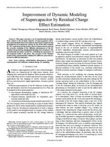
where δa is the aileron deflection, K is the induced drag constant, and Cm,AC is the quarter-chord pitching moment coefficient which is positive nose up and independent of the angle of attack. The function C (k) is called the Theodorsen’s function which is a complex-valued function of the reduced frequency parameter k bω (54) k= u cos Λ where ω is the flutter or aeroelastic mode frequency. (2) C (k) can also be expressed in terms of Hankel functions of the second kind Hn (k) as (2)
C (k) =
H1 (k) (2)
(2)
H1 (k) + iH0 (k)
= F (k) − iG (k)
(55)
where F (k) > 0 and G (k) > 0. When k = 0, the airfoil motion is steady and C (k) is real and unity. As k increases, there is a phase lag introduced as the magnitude of G (k) increases as shown in Figs. 4 and 5. The limiting values of F (k) and G (k) are 1/2 and 0 as k → ∞.17 10 of 20 American Institute of Aeronautics and Astronautics
1 F(k) 0.9
G(k)
0.8
F(k) or G(k)
0.7 0.6 0.5 0.4 0.3 0.2 0.1 0 0
0.5
1
1.5
2 k
2.5
3
3.5
4
3.5
4
Fig. 5 - Theodorsen’s Function 0 −2
−tan−1[G(k)/F(k)]
−4 −6 −8 −10 −12 −14 −16 0
0.5
1
1.5
2 k
2.5
3
Fig. 6 - Theodorsen’s Function Phase lag The aerodynamic forces and moment on a 2-D wing section acting at the elastic center in the reference frame D are determined by fyc −L sin (αc + γ ) + D cos(αc + γ ) d c (56) L cos (αc + γ ) + D sin (αc + γ ) fz = dx � −M − 21 + a b [L cos αc + D sin αc ] mcx
as illustrated in Fig. 7.
Fig. 7 - Airfoil Forces and Moment
11 of 20 American Institute of Aeronautics and Astronautics
For a small elastic angle of attack, the circulatory unsteady aerodynamic forces and moment are approximated as fyc Cy,α Cy c (57) fz = ρ∞ bu2 cos2 Λ Cz + C (k) αe Cz,α c 2bCx 2bCx,α mx
where Cy , Cz , and Cx are the force and moment coefficients due to rigid-body aerodynamics −CL sin (α ∗ + γ ) + CD cos (α ∗ + γ ) Cy Cz = CL cos (α ∗ + γ ) + CD sin (α ∗ + γ ) � −Cm − 41 + 2a [CL cos α ∗ + CD sin α ∗ ] Cx
(58)
and Cy,α , Cz,α , and Cx,α are the derivatives of the force and moment coefficients with respect to the angle of attack − (CL,α + CD ) sin (α ∗ + γ ) + (CD,α − CL ) cos (α ∗ + γ ) Cy,α ) cos (α ∗ +�γ ) + (CD,α − CL ) sin (α ∗ + γ )i D Cz,α = (CL,α + C h� � − 14 + 2a c∗L,α + c∗D cos α ∗ + (CD,α − CL ) sin α ∗ Cx,α
C.
(59)
Aerodynamic Damping
Dynamic stability of a system is dependent on dissipative forces acting on it. The dissipative forces contribute positively to damping of the system. Dynamically stable systems require positive damping. Aeroelastic forces give rise to the aerodynamic damping mechanism that influences aerodynamic stability of an oscillating wing or a flight vehicle. Positive aerodynamic damping results in aerodynamically stable operation. Conversely, negative aerodynamic damping causes flutters and self-excited vibrations. Flutter boundaries are defined by air speed at which the aerodynamic damping crosses from a positive value to a negative value. Consider the case when p = 0 and γ = 0, the damping forces are obtained from the noncirculatory and circulatory components of the aeroelastic forces as � � fyd Cy,α −πγ α Vxt tan Λ d 2 2 2 − Wxt tan Λ − Θt + ρ∞ bu cos ΛC (k) αe Cz,α fz = ρ∞ b u cos Λ π � cos Λ 2bCx,α π 21 − a − aγ 2 b mdx (60) For a harmonic motion, the structural deflections may be expressed as ΦΘ (x) Θ iω t (61) W = ΦW (x) e ΦV (x) V where ΦΘ , ΦW , and ΦV are the elastic mode shapes of the torsion, flapwise bending, and chordwise bending modes, respectively. Then, the elastic angle of attack may be expressed as
αe = (αr + iαi ) eiω t
(62)
where αr and αi are the real and imaginary parts of αe ′
′ α ΦV tan Λ αr = − ΦW tan Λ − ΦΘ cos Λ # " � ΦW + 12 − a bΦΘ − α ∗ ΦV αi = −ω u cosΛ
where the prime denotes derivative with respect to x. 12 of 20 American Institute of Aeronautics and Astronautics
(63)
(64)
The damping forces and pitching moment are then obtained as the imaginary part of the circulatory aeroelastic forces and pitching moment fyd −πγ Cy,α d 2 2 2 iω t iω t + ρ∞bu cos Λ [−G (k) αr + F (k) αi ] ie Cz,α (65) fz = ρ∞ b u cosΛαr ω ie π � 2bCx,α π 21 − a − aγ 2 b mdx which can also be written as � � fyd α Vxt tan Λ d 2 − Wxt tan Λ − Θt fz = ρ∞ b u cos Λ cosΛ π mdx
Cy,α −πγ G (k) π Cz,α − k � 1 2 2bCx,α 2 − a − aγ b � � � � Cy,α 1 − a bΘt + α ∗Vt Cz,α + ρ∞ bu cosΛF (k) −Wt − 2 2bCx,α
(66)
It should be noted that the sign of the aerodynamic damping is influenced by the sign of CL,α + CD . While CD is always positive, CL,α can be negative when the airfoil is stalled. Therefore, it is possible that the aerodynamic damping can become negative. If the overall damping which includes structural damping that inherently exists in the wing structure transitions from a positive value to a negative value, the ensuing motion will be aerodynamically unstable due to positive work inputs to the wing by the air. For example, the generalized damping coefficient for the flapwise bending, by neglecting the term CD,α − CL and the contributions from chordwise bending and torsion, may be estimated as R ρ∞ u cosΛF (k) b (CL,α + CD ) cos α ∗ (x) [ΦW (x)]2 dx ζW ≃ (67) R 2ω ρ A [ΦW (x)]2 dx It is obvious that if CLα becomes negative then if it possible for ζW to be negative. The aerodynamic damping for the torsion is more complex. In general, the aerodynamic damping for the combined bending-torsion motion must be analyzed by matrix analysis
VI. Gravity and Propulsive Forces and Moments The gravity and propulsive forces are significant contributing active forces acting on the aircraft airframe. These forces can influence structural deflections of a wing. For high-aspect ratio, flexible wings, gravity can significantly offset wing bending deflections at low airspeed. Similarly, the engine thrust force can also affect twist and bending deflections of flexible wings. A.
Propulsive Forces and Moments
To deal with the propulsive force, we assume that the left engine produces a thrust vector aligned with the b1 -direction at the thrust center E in the rigid-body aircraft reference frame B. Point E is assumed to be located relative to point P at x = xE , y = yE , and z = zE forward and below the elastic center of the wing section in the reference frame D. Since the engine is mounted on a flexible wing, then the thrust center E is dependent on the wing structural deflections. Since the engine thrust is a concentrated force, it can be formulated as a distributed force using the Dirac delta function which is defined as ∞ , x = x 0 δ (x − x0 ) = (68) 0 , x 6= x 0
such that for an arbitrary function g (x), then
Z
g (x) δ (x − x0 ) dx = g (x0 )
13 of 20 American Institute of Aeronautics and Astronautics
(69)
Then, the distributed forces in the reference frame D due to the small structural rotation angle δ are computed using three successive rotation matrix multiplication operations as fxe − sin Λ 1 −Vx 0 1 0 −Wx 1 0 0 e 1 0 − cosΛ 0 Vx fy ≈ δ (x − xE ) T 0 1 −Θ 0 1 0 0 0 1 Wx 0 1 0 Θ 1 fze − sin Λ + Vx cos Λ ≈ δ (x − xE ) T − cos Λ − Vx sin Λ (70) −Wx sin Λ − Θ cosΛ
where T is the engine thrust. The distributed thrust forces are transformed back into the aircraft reference frame B as fxe − sin Λ + Vx cos Λ − sin Λ − cos Λ 0 1 e fy ≈ δ (x − xE ) T − cos Λ sin Λ 0 − cos Λ − Vx sin Λ ≈ δ (x − xE ) T −Vx e −Wx sin Λ − Θ cosΛ 0 0 −1 Wx sin Λ + Θ cosΛ fz (71) The left engine thrust force can now be obtained by integration as TL =
Z
δ (x − xE ) T [b1 − Vx b2 − (Wx sin Λ + Θ cosΛ) b3 ] dx = T [b1 − Vx b2 + (Wx sin Λ + Θ cosΛ) b3 ]x=xE
(72)
It can be observed that the structural deflections at the thrust center generate additional thrust force components in the b2 - and b3 -directions. Thus, the coupled effect between the propulsive force and structural deflections can be significant if the wing is highly flexible and the engine thrust is large. The distributed moments due to the propulsive force in the reference frame D are computed as mex yE fze − zE fye (zE − yE Wx ) sin Λ + (−zE Vx − yE Θ) cos Λ e (73) my = zE (sin Λ − Vx cos Λ) = δ (x − xE ) T −zE fxe e e yE (Wx sin Λ + Θ cosΛ) −yE fx mz B.
Gravity Forces and Moments
The gravity can exert significant forces and moments on a wing. The gravity forces include the weight of the wing including fuel, and the engine weight. The distributed gravity forces can be expressed in the reference frame D as g fx sin θ sin Λ − cos θ sin φ cos Λ g (74) fy ≈ [ρ Ag + δ (x − xE ) mE g] sin θ cos Λ + cos θ sin φ sin Λ g − cos θ cos φ fz
where ρ is the mass density of the wing including fuel, A is the cross sectional area, and mE is the engine mass. Assuming that the center of gravity of the wing and fuel coincides with the elastic axis, and the center of gravity of the engine coincides with the thrust center, then the distributed moments due to gravity in the reference frame D are computed as mgx −yE cos θ cos φ − zE (cos Λ + cos θ sin φ sin Λ) g (75) my = δ (x − xE ) mE g −zE (sin θ sin Λ − cos θ sin φ cos Λ) g mz −yE (sin θ sin Λ − cos θ sin φ cos Λ)
VII. Coupled Structural Dynamic Equations The equilibrium conditions describe the force and moment balance of all forces and moments acting on a wing. The resulting force and moment equilibrium conditions are given by 0 fx Fx ∂ (76) Fy + fy = 0 ∂x 0 fz Fz 14 of 20
American Institute of Aeronautics and Astronautics
0 FzVx − FyWx mx Mx ∂ My + my + −FxWx + Fz = 0 ∂x 0 −FxVx + Fy mz Mz
(77)
where fx , fy , fz , mx , my , and mz are distributed forces and moments due to inertial, aeroelastic, gravity, and propulsive effects g i a e f(x,y,z) = f(x,y,z) + f(x,y,z) + f(x,y,z) + f(x,y,z) (78) m(x,y,z) = mi(x,y,z) + ma(x,y,z) + mg(x,y,z) + me(x,y,z)
(79)
The shear forces Fy and Fz can be eliminated by solving the last two equations in Eq. (77). Neglecting nonlinear terms, the equilibrium conditions can be written as
∂ Mx + mx − m∗y Vx + m∗z Wx = 0 ∂x � Zx � ∂ 2 My ∂ my ∂ ∗ Wx fx d σ = 0 + − fz + ∂ x2 ∂x ∂x 0 � Zx � ∂ 2 Mz ∂ mz ∂ ∗ fx d σ = 0 Vx + − fy + ∂ x2 ∂x ∂x 0
(80) (81) (82)
where the superscript * denotes rigid-body forces and moments, and σ is a dummy variable that replaces x. The resulting equations are three structural dynamic partial differential equations that relate the flapwise bending, chordwise bending, and torsion with the coupled effects under consideration. The integral term involving the rigidbody inertial force fx∗ can be important if the inertial acceleration of the aircraft is significant. This term gives rise to the rotational stiffening effect when the angular speed of a wing structure is large. A.
Example
Consider a flight vehicle with non-twisted, unswept wings γ = 0, Λ = 0, on a horizontal flight, θ = 0, making a constant roll rate p maneuver. The rigid-body and elastic angles of attack from Eqs. (39) and (42) reduce to
α∗ = α +
−p (xP + x) u
(83)
� Wt + 21 − a bΘt pzP αe = −Wx −Θ− (84) u u cos Λ Neglecting the chordwise bending motion and the damping forces, then the structural dynamic equations for flapwise bending and torsion are ��
� � � � 3 1 2 − (GJΘx )x − ρ p Izz Θ + ρ IxxΘtt + ρ∞ π b − a + 2a bΘtt + − 2a Wtt 8 2 �� � � pzP 1 + a Wx +Θ − ρ∞b2 u2 cos2 ΛF (k)Cz,α 2 u � � �� � � 1 G (k) 1 3 + ρ∞ b Cz,α + a Wtt + − a bΘtt = ρ∞ bu2 cos2 Λ2bCx k 2 2 2
3
� � Z x 2 ∗ ρ Aax d σ (EIyyWxx )xx + ρ A Wtt − p W + ρ p IyyWx − ρ IyyWxtt + Wx 0 x �� � � � � pz 1 P − 2a bΘtt + 2Wtt + ρ∞ bu2 cos2 ΛF (k)Cz,α Wx +Θ + ρ∞ π b2 2 u � � � � 1 G (k) Wtt + − a bΘtt = −ρ Aa∗z + ρ∞bu2 cos2 ΛCz − ρ Ag cos φ − ρ∞b2Cz,α k 2 2
(85)
�
15 of 20 American Institute of Aeronautics and Astronautics
(86)
For a quasi-steady-state motion when the wing responds statically to the inertial, aeroelastic, and propulsive forces, by setting all the partial time derivative terms to zero in the above equations, one obtains �� � � pzP 1 2 2 2 2 − (GJΘx )x − ρ p Izz Θ − ρ∞b u cos ΛCz,α + a Wx + Θ = ρ∞ bu2 cos2 Λ2bCx (87) 2 u � � Z x � � pz P 2 ∗ ρ Aax d σ + ρ∞ bu2 cos2 ΛCz,α Wx +Θ (EIyyWxx )xx − ρ Ap W + ρ p IyyWx + Wx u 0 x � 2 = ρ A w˙ + p z p + ρ∞bu2 cos2 ΛCz − ρ Ag cos φ 2
B.
(88)
Solution Methods
Structural dynamic problems are generally solved by the finite-element analysis (FEA) method. The FEA method formulates a structural dynamic problem described by a system of partial differential equations as a matrix equation in terms of the mass matrix, stiffness matrix, and force vector in the form of19 � � � −ω 2 M i + M n − ω G (k) H + (K s + K c ) U = F (89)
where M i is an inertial mass matrix, M n is an apparent mass matrix due to noncirculatory forces, K s is a structural stiffness matrix, K e is an aeroelastic stiffness matrix due to circulatory forces, F is a force vector, H is a matrix due to the phase lag resulting from vortex shedding, and U is a solution vector. Due to the aeroelasticity, the matrices H and K c are non-symmetric, but they can be decomposed into symmetric and skew-symmetric matrices. Only the symmetric matrices are retained for the solution.16 Equation (89) is a generalized nonlinear eigenvalue problem due to the presence of G (k) which is a nonlinear function of ω . Thus, the eigenvalue solution is an iterative process by first guessing for k, and then solving an generalized quadratic eigenvalue problem for ω , which in turn is used to update k. An alternate approach is to simply ignore G (k) since G (k) is a small value. The eigenvalue problem then reverts to the standard form which can easily be solved. There are two types of problems: 1) static aeroelasticity and 2) dynamic aeroelasticity. The static aeroelasticity describes physical effects that do not involve dynamic responses of a wing structure such as divergence and control reversal. The wing-deflected shape can influence the aerodynamics of a vehicle. The static deflection can be large if the wing structure is highly flexible. The static problem can be formulated as a coupled fluid-structure interaction problem. The vehicle is modeled by computational fluid dynamics (CFD) method for aerodynamic calculations of coefficients and derivatives. The results are used as inputs to the FEA model to compute the vehicle deflected shape. This shape is then used as the new input to the CFD model and the process is repeated until the solution converges. The dynamic aeroelasticity describes flutter behaviors and transient responses of a wing structure that is subject to wind gusts or instantaneous control surface deflections. Dynamic responses of the wing structure can affect the overall vehicle control and stability. The solution of the dynamic problem can be solved by implementing the modal decomposition method on the eigenvalue solution of the FEA. Elastic modes can be described by a set of uncoupled, scalar second-order differential equations that can be readily analyzed. For a symmetric aircraft configuration for which both wings are identical, two types of elastic modes are present. Symmetric modes are those for which the structural deflections of both wings are in the same sense. Anti-symmetric modes are those that exhibit structural deflections in an opposite sense between the left and right wings. Figure 8 illustrates symmetric and anti-symmetric modes.
16 of 20 American Institute of Aeronautics and Astronautics
Fig. 8 - Symmetric and Anti-Symmetric Modes Because of the symmetry that exists at the fuselage centerline, only one wing can be analyzed with appropriate boundary conditions.20 The fuselage and tails contribute to the elastic modes as a concentrated mass, half of which is located at each of the wing roots. Then for symmetric modes, the boundary conditions at the wing roots must match the bending displacement slopes for both left and right wings, and are given by " # " # Wx (0,t) 0 = (90) Vx (0,t) 0 The torsion boundary condition for symmetric modes is null which corresponds to a free-free boundary condition. For anti-symmetric modes, the boundary conditions at the wing roots must be zero 0 Θ (0,t) (91) W (0,t) = 0 0 V (0,t)
To be more precise, the entire aircraft structure including wings, fuselage, and tails can be discretized and solved by the FEA. In particular, the whole-aircraft analysis becomes necessary if the aircraft configuration is asymmetric. The structural deflections are obtained from the FEA solution and can be expressed as ¯ (x) ΨΘ, j (x) ΦΘ, j (x) Θ Θ (x,t) n m (92) W (x,t) = W¯ (x) + ∑ q j (t) ΦW, j (x) + ∑ r j (t) ΨW, j (x) j=1 j=1 ΨV, j (x) ΦV, j (x) V (x,t) V¯ (x)
where the overbar symbol denotes static solutions, Φ(Θ,W,V ), j and Ψ(Θ,W,V ), j are normalized eigenvectors, q j and r j are generalized coordinates for the j − th symmetric and anti-symmetric modes that solve a set of uncoupled scalar differential equations gen gen gen mgen ˙ w, ˙ u, w, p, ˙ p, δa ) , j q¨ j + c j q˙ j + k j q j = g j (u,
j = 1, . . . , m
(93)
gen gen gen mgen ˙ w, ˙ u, w, p, ˙ p, δa ) , j r¨ j + c j r˙ j + k j r j = h j (u,
j = 1, . . . , n
(94)
The scalar quantities mgen , cgen , and kgen
are called generalized mass, damping, and stiffness matrices, respectively, and ggen and hgen are called the generalized forces. They can be computed using the standard procedure in elementary vibration theory.
17 of 20 American Institute of Aeronautics and Astronautics
VIII. Flight Dynamics of Flexible Aircraft A flexible aircraft has various elastic modes that can participate in the motion to affect its flight characteristics. Wing elastic modes constitute significant structural dynamics of flexible aircraft. In addition, fuselage bending modes are also known to affect pitch characteristics. There are other elastic modes such as those due to horizontal stabilizers and vertical stabilizer. In totality, all these components contribute to flight characteristics and should be included in the equations of motion. The coupled flight-structural dynamics can be quite complicated when all elastic modes are accounted for. In this study, we will only focus on the coupling of wing elastic modes and rigid-body flight dynamics. A.
Aeroelastic Forces and Moments in Aircraft Reference Frame
We define the elastic angle of attack as a function of the structural deflections as � i� � h � α ωy (zP + zC ) αe (Θ,Wx ,Vx ) = Vx −Θ − γ − Wx tan Λ − cos Λ u cosΛ
(95)
Wing structural deflections affect the lift characteristics of an aircraft. Assuming both the left and right wings are of the same geometry, then the elastic angle of attack contributes to the static and dynamic forces and the moments in the aircraft reference frame B as −Cy,α cos Λ ∆X¯ (u, w, p, α , θ , φ , δa ) Z L � ¯ ¯ W¯ x , V¯x ρ∞ bu2 cos2 Λαe Θ, (96) −Cz,α ∆Z (u, w, p, α , θ , φ , δa ) = 2 dx 0 ¯ ∆M (u, w, p, α , θ , φ , δa ) −2bCx,α cos Λ ∆X jS (u, w, p, α , θ , φ , δa ) Z L � −Cy,α cos Λ 2 2 S ρ∞ bu cos Λαe ΦΘ, j , ΦW, j , ΦV, j ∆Z j (u, w, p) −Cz,α = 2F (k) 0 −2bCx,α cos Λ ∆M Sj (u, w, p) " # " Z L � ∆Y jA (u, w, p, α , θ , φ , δa ) Cy,α sin Λ = 2F (k) ρ∞ bu2 cos2 Λαe ΨΘ, j , ΨW, j , ΨV, j A 0 −2bCx,α sin Λ ∆L j (u, w, p)
dx
(97)
dx
(98)
#
where X, Y , and Z are the aircraft axial, side, and normal forces, L, M, and N are the aircraft rolling, pitching, and yawing moments, the overbar symbol denotes static forces and moments, and the superscript Φ and Ψ denote dynamic forces and moments corresponding to symmetric and anti-symmetric modes, respectively. It can be seen that symmetric modes affects forces and moments in the longitudinal direction. On the other hand, anti-symmetric modes affects the lateral motion of the aircraft. The aeroelastic forces and moments contribute to the flight dynamics of an aircraft in such a way that elastic deflections can adversely affect the rigid-body aircraft responses and can result in elastic mode interactions with a flight control system. These interactions necessitate the use of aeroelastic mode filters in the flight control design in order to attenuate structural dynamic responses of flexible aircraft lifting surfaces. B.
Propulsive Forces and Moments in Aircraft Reference Frame
In addition, the elastic modes also affect the propulsive forces and moments generated by wing-mounted engines. The propulsive force for the left engine is given by Eq. (72). Assuming a twin-engine aircraft configuration, the propulsive force for the right engine is given by TR = T [b1 − Vx b2 + (Wx sin Λ − Θ cosΛ) b3 ]x=xE
(99)
where V , W , and Θ are defined according to the right wing reference frame C such that V and Θ are in the opposite sense to those deflections in the reference frame D, i.e., V is positive towards the leading edge and Θ is positive nose up. The total static and dynamic propulsive forces are then computed to be X T = 2T 18 of 20 American Institute of Aeronautics and Astronautics
(100)
"
∆Y jTA ∆Z Tj S
#
= 2T
"
′
−ΨV, j ′ ΦW, j sin Λ + ΦΘ, j cos Λ
#
(101) x=xE
where the superscript T S and TA denote thrust forces due to symmetric and anti-symmetric modes, respectively. Thus, symmetric modes create a normal force and anti-symmetric modes create a side force due to the combined thrust of the two engines. The propulsive moment is computed as � � M = rxE b1 − ryE b2 + rzE b3 × TL + rEx b1 + ryE b2 + rzE b3 × TR (102) � where rxE , ryE , rzE are the coordinates of the right engine thrust center relative to the aircraft center of gravity in the reference frame B. Upon evaluation, this yields the total static and dynamic propulsive moments
∆LTA j ∆M Tj S = 2T ∆N TA j
M T = 2TrzE � ′ � ′ rzE ΨV, j − ryE ΨW, j sin Λ + ΨΘ, j cos Λ � � ′ −rxE ΨW, j sin Λ + ΨΘ, j cos Λ ′
−rxE ΨV, j
(103)
(104) x=xE
It can be seen that symmetric modes result in an additional pitching moment, whereas anti-symmetric modes create both rolling and yawing moments. C.
Equations of Motion
The flight dynamic equations with elastic mode and propulsive force interactions can now be written as m
m (u˙ − rv + qw + gsinθ ) = X T + C¯L qS ¯ sin α − C¯D qS ¯ cos α cos β + ∆X¯ + ∑ ∆X jS q j
(105)
j=1
n � m (v˙ + ru − pw − gcosθ sinφ ) = C¯Y qS ¯ − C¯D qS ¯ sin β + ∑ ∆Y jTA + ∆Y jA r j
(106)
j=1
m � ¯ cos α − C¯D qS ¯ sin α cos β + ∆Z¯ + ∑ ∆Z Tj S + ∆Z Sj q j m (w˙ − qu + pv − gcosθ cosφ ) = −C¯L qS
(107)
j=1
n � A L = C¯l qS ¯ b¯ + ∑ ∆LTA j + ∆L j r j
(108)
j=1
m � M = C¯m qS ¯ c¯ + M T + ∆M¯ + ∑ ∆M Tj S + ∆M Sj q j
(109)
j=1
n
N = C¯n qS ¯ b¯ + ∑ ∆N TA j rj
(110)
j=1
where the coefficients with the overbar are for the aircraft, q¯ is the dynamic pressure, c¯ isthe mean aerodynamic chord, b¯ is the wing span, S is the reference wing area, and β is the angle of sideslip. These equations constitute six degrees of freedom dynamics that are coupled with structural dynamics equations from Eqs. (93) and (94), which are obtained from the FEA. In analyzing the elastic modes, only the first few significant modes whose natural frequencies are within a flight control frequency bandwidth are usually considered. These elastic modes can become excited by the flight control surface deflections. Examining Eqs. (105) to (110) reveals that symmetric modes only affects longitudinal dynamics of aircraft. On the other hand, anti-symmetric modes play a role in both lateral and directional dynamics.
19 of 20 American Institute of Aeronautics and Astronautics
IX. Conclusions This paper has presented an integrated flight dynamic modeling method for flexible aircraft. The method combines structural dynamics of an equivalent beam model of a flexible wing with rigid-body flight dynamics that accounts for coupled effects due to aeroelasticity, inertial forces, and propulsive forces. A formulation of aeroelastic angle of attack for the combined chordwise bending, flapwise bending, and torsion is developed that extends Theodorsen’s theoretical result. The structural dynamic equations can be solved using the finite-element method to determine static and dynamic structural deflections as functions of aircraft states. The elastic modes are decomposed into symmetric and anti-symmetric modes with associated generalized coordinates. The standard flight dynamic equations for six degree-of-freedom motion then includes the generalized coordinates as additional state variables. These equations become coupled with a set of uncoupled second-order differential equations in terms of the generalized coordinates that describe the elastic responses of the wing structure. These equations must be solved simultaneously to obtain a solution that describes the combined motion of flexible aircraft.
References 1 Pendleton, E., Lee, M., and Wasserman, L., “Application of Active Flexible Wing Technology to the Agile Falcon”, AIAA Journal of Aircraft, Vol. 29, No. 3, May-June 1992.Pendleton, E., Lee, M., and Wasserman, L., “Application of Active Flexible Wing Technology to the Agile Falcon”, AIAA Journal of Aircraft, Vol. 29, No. 3, May-June 1992. 2 Wilson, J.R., “Active Aeroelastic Wing: a New/Old Twist on Flight”, Aerospace America, September 2002. 3 Pratt, R.W., Taylor, R., and Caldwell, B.D., “Aeroservoelasticity: Key Issues Affecting the Design of Flight Control Systems”, IEEE Control Conference Publication No. 389, March 1994. 4 Gupta, K.K., Brenner, M.J., and Voelker, L.S., “Development of an Integrated Aeroservoelastic Analysis Program and Correlation with Test Data”, NASA Technical Paper 3120, May 1991. 5 Cheng, P.Y. and Hirner, T.J., “Aircraft Aeroservoelastic Compensation Using Constrained Optimization”, AIAA Structures, Structural Dynamics, and Materials Conference, AIAA-1992-2399, April 1992. 6 Brenner, M.J., “Aeroservoelastic Modeling and Validation of a Thrust-Vectoring F/A-18 Aircraft”, NASA Technical Paper 3647, September 1996. 7 Strass, H.K., and Stephens, E.W., “An Engineering Method for Determination of Aeroelastic Effects upon the Rolling Effectiveness of Ailerons on Swept Wings”, NACA Research Memorandum L53H14, November 1953. 8 Theodorsen, T. and Garrick, I.E., “Mechanism of Flutter - a Theoretical and Experimental Investigation of the Flutter Problem”, NACA Report 685, 1940. 9 Theodorsen, T, “General Theory of Aerodynamic Instability and the Mechanism of Flutter”, NACA Report 496, 1935. 10 Garrick, I.E., “ Bending-Torsion Flutter Calculations Modified by Subsonic Compressibility Corrections”, NACA Report 836, 1946. 11 Houbolt, J.C. and Brooks, G.W., “Differential Equations of Motion for Combined Flapwise Bending, Chordwise Bending, and Torsion of Twisted Nonuniform Rotor Blades”, NACA Technical Note 3905, February 1957. 12 Lee, U., “Equivalent Continuum Beam-Rod Models of Aircraft Wing Structures for Aeroelastic Analysis”, AIAA Structures, Structural Dynamics, and Materials Conference, AIAA-1994-1695, April 1995. 13 Shearer, C.M. and Cesnik, C.E.S., “Nonlinear Flight Dynamics of Very Flexible Aircraft”, AIAA Atmospheric Flight Mechanics Conference, AIAA-2005-5805, August 2005. 14 Meirovitch, L. and Tuzcu, I, “Integrated Approach to Flight Dynamics and Aeroservoelasticity of Whole Flexible Aircraft - Part I: System Modeling”, AIAA Guidance, Navigation, and Control Conference, AIAA-2002-4747, August 2002. 15 Meirovitch, L. and Tuzcu, I, “Integrated Approach to Flight Dynamics and Aeroservoelasticity of Whole Flexible Aircraft - Part II: Control Design”, AIAA Guidance, Navigation, and Control Conference, AIAA-2002-5055, August 2002. 16 Bisplinghoff, R.L and Ashley, H., Principles of Aeroelasticity, Dover Publications, Inc., New York, 1975. 17 Abramson, N., An Introduction to the Dynamics of Airplanes, Dover Publications, Inc., New York, 1971. 18 Hodges, D.H. and Pierce, G.A., Introduction to Structural Dynamics and Aeroelasticity, Cambridge University Press, 2002. 19 Hughes, T.J.R., The Finite Element Method: Linear Static and Dynamic Finite Element Analysis, Dover Publications, Inc., 2000. 20 Przemieniecki, J.S., Theory of Matrix Structural Analysis, Dover Publications, Inc., New York, 1985.
20 of 20 American Institute of Aeronautics and Astronautics