Dec 2, 2014 - Esmaeil Jahanshahi and Sigurd Skogestad, Norwegian University of Science and ... tant unstable (right-half-plane) zeroes in the model.
Simplified Dynamic Models for Control of Riser Slugging in Offshore Oil Production Esmaeil Jahanshahi and Sigurd Skogestad, Norwegian University of Science and Technology
Summary
Elaborated models, such as those used for simulation purposes [e.g., in the OLGA® simulator (Bendiksen et al. 1991)], cannot be used for model-based control design because these models use too many state variables and the model equations are not usually available for the user. The focus of this paper is on deriving simple, dynamical models with few state variables that capture the essential dynamic behavior for control. We propose a new simplified dynamic model for severe-slugging flow in pipeline/riser systems. The proposed model, together with five other simplified models found in the literature, are compared with results from the OLGA simulator. The new model can be extended to other cases, and we consider also a well/ pipeline/riser system. The proposed simple models are able to represent the main dynamics of severe-slugging flow and compare well with experiments and OLGA simulations.
Introduction
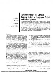
Severe-slugging-flow regimes usually occur in pipeline/riser systems that transport a mixture of oil and gas from the seabed to the surface (Taitel 1986). Such flow regimes, also referred to as “riser slugging,” are characterized by severe flow and pressure oscillations. Slugging problems have also been observed in gas lifted oil wells in which two types of instabilities—casing heading and density wave instability—have been reported (e.g., Hu and Golan 2003). Slugging has been recognized as a serious problem in offshore oil fields because the irregular flow caused by slugging can cause serious operational problems for downstream surface facilities (e.g., overflow of inlet separators). Therefore, effective methods to handle or remove riser slugging are needed, and many efforts have been made to prevent such occurrences (Courbot 1996; Havre et al. 2000). The conventional solution is to partially close the topside choke valve (choking), but this may reduce the production rate, especially for fields in which the reservoir pressure is relatively low. Therefore, a solution that guarantees stable flow and the maximum possible production rate is desirable. Fortunately, automatic feedback control has been shown to be an effective strategy to eliminate the slugging problem. As shown in Fig. 1, the topside choke valve is usually used as the manipulated variable to regulate (control) the riser-base pressure (Prb) at a given pressure set point (Pset). Such a system is referred to as “antislug control,” and it aims at stabilizing the flow in the pipeline at the operating conditions that, without control, would lead to riser slugging. Different antislug-control strategies have been tested in practice (Havre et al. 2000) and experimentally (Godhavn et al. 2005). OLGA is a commercial multiphase simulator used widely in the oil industry (Bendiksen et al. 1991). When the development of this simulator was initiated in the 1980s, one of motivations was to study Copyright © 2014 Society of Petroleum Engineers Original SPE manuscript received for review 16 December 2013. Revised manuscript received for review 22 July 2014. Paper (SPE 172998) peer approved 7 August 2014.
64
Oil and Gas Facilities • December 2014
Pset
PC
Z
Topside choke
PT Prb
Inlet separator
Riser
Subsea wells Fig. 1—Preventing slug flow by control of riser-base pressure. (PC=pressure controller and PT=pressure transmitter.)
the dynamics of slow flow regimes for offshore oil fields. There has been some research on riser slugging conducted with the OLGA simulator to test antislug control (Fard et al. 2006); however, the model equations coded in commercial simulators are not openly available and appear as a black box to the end user. In addition, the OLGA simulator uses numerous correlations with parameters that are calibrated on the basis of field data. The OLGA simulator works by discretizing the pipe into multiple segments. The model accuracy increases by increasing the number of the segments, but this results in many ordinary-differential equations (ODEs). However, for controller design, we need a fully known and preferably simple model with as few ODEs as possible. When we refer to simple models in this paper, the number of ODEs, or equivalently, the number of “states,” will be called “dimensions” of the model. The focus of this paper is on deriving a simple dynamical model that captures the essential behavior for control—namely, the onset of slugging, not the slugging itself. The aim is to avoid the slug flow regime and, instead, operate at a steady- (nonslug-) flow regime. Therefore, the shape and length of the slugs are not the main concerns in this modeling. For simplicity, two-phase flow (gas phase and bulk liquid phase) is assumed in the model. To use the model for a three-phase gas/oil/ water system, the bulk liquid phase includes the oil and water. As an approximation, the density and other parameters for the bulk liquid phase are the weighted averages (based on volume fractions) of the parameters for the oil and water phases. We also need to ignore the slip between oil and water phases. This approximation should not affect the prediction of slugging onset significantly, except for special cases in which the slip velocity between the water and oil phases exceeds a certain value that is beyond the scope of this study. In such cases, a slip model must be included to improve the model prediction. Five simplified dynamical models for the pipeline/riser systems were found in the literature. The “Storkaas model” (Storkaas et al. 2003) is a 3D state-space model that has been used for controllability analysis (Storkaas and Skogestad 2007). The “Eikrem model” (Tuvnes 2008; Eikrem 2008) is a 4D state-space model. Another sim-
plified model, referred to as the “Kaasa model” (Kaasa et al. 2008), predicts the pressure at the bottom of the riser only. The “Nydal model” (Martins da Silva et al. 2010) is the only model that includes friction in the pipes. The most recently published simplified model is the “Di Meglio model” (Di Meglio et al. 2009, 2010). In addition, we present in this paper a new four-state model that includes features of the other five models. The six models are simulated in the time domain and compared with results from the more-detailed OLGA model in the following five aspects, listed in order of importance: • Critical valve opening for onset of slugging • �Frequency of oscillations at the critical point (onset of slugging) • �Dynamical response to a step change in the valve opening (nonslug regime) • Steady-state pressure and flow-rate values (nonslug regime) • �Maximum and minimum (pressure and flow rate) of the oscillations (slug regime) The simplified models are also analyzed linearly in the frequency domain, where we consider the location of unstable poles and important unstable (right-half-plane) zeroes in the model. The results presented in this paper have been partially presented by Jahanshahi and Skogestad (2011) and Jahanshahi et al. (2012). In the present paper, we compare the new model with the experiments, and we extend it to a well/pipeline/riser system. This paper is organized as follows. First, we present our new simplified model for pipeline/riser systems. Then, we compare the proposed model and the other simple models with the results from the OLGA simulator and experiments. Finally, we extend this model to well/pipeline/riser systems and compare the extended model with OLGA simulations.
New Simplified Four-State Model
Mass-Balance Equations for Pipeline and Riser. For the new simplified model, consider the schematic of the system presented in Fig. 2. The four differential equations in the proposed model are simply the mass-conservation law for the gas and liquid phases in the pipeline and riser sections:
d ( mG ) p dt d ( mL ) p dt
d ( mG )r dt
= ( wG )in − ( wG )rb ,.................................................. (1a) = ( wL )in − ( wL )rb ,...................................................(1b)
= ( wG )rb − ( wG )out ,................................................. (1c)
and
d ( mL )r dt
= ( wL )rb − ( wL )out ,..................................................(1d)
The four state variables in the model are (mG)p = mass of gas in the pipeline, kg (mL )p = mass of liquid in the pipeline, kg (mG)r = mass of gas in the riser, kg (mL )r = mass of liquid in the riser, kg The state variables are masses; therefore, they are non-negative values. The time derivatives of the state variables appear on the left side of the state equations (Eqs. 1a through 1d). On the right side of the state equations, w (kg/s) denotes mass-flow rate, and the subscripts “in,” “rb,” and “out” stand for “inlet,” “riser base,” and
Choke valve with opening Z1 mG,r Prt VG,r ρG,r αL,rt
PS wout
Lh
mG,p Pin VG,p ρG,p αl,p wG,in wL,in
h