Dynamic Path Planning with Spiking Neural Networks Ulrich Roth, Marc Walker, Arne Hilmann, and Heinrich Klar TU-Berlin, Institut für Mikroelektronik, Jebensstr. 1, D-10623 Berlin E-Mail:
[email protected]
ABSTRACT: The path planning problem is relevant for all applications in which a mobil robot should autonomously navigate. Finding the shortest path in an environment that is only partialy known and changing is a difficult problem. Replaning the entire path when the robot encounters new obstacles is computational inefficient. Starting with an initial path and than modify the path locally does not guarantee to find the optimal path. In this paper we present a new path planning algorithm, the radar path planner, which is capable of planning paths in unknown, partially known, and changing environments. Furthermore we present an efficient implementation of the path planner with spiking neurons.
1
I NTRODUCTION
Spike-processing networks are mainly used for figure-ground segregation and object recognition via dynamic associativ memory [1][2]. They have been introduced according to experimental results which suggest that temporal correlation of activity might be used by the brain as a code for figure-ground segregation and feature binding [1][3]. The special features of spiking neurons are their dynamic behavior and the communication via spikes, besides the parallism of neural networks. These features inspired us to apply spiking neurons to a field in which temporal behavior and computational efficiency is important: the path planning problem. The path planning problem is relevant for all applications in which a robot should autonomously navigate. The objective of a path planner is to move the robot from some location in the world to a goal location, such that it avoids all obstacles and minimizes a positive cost metric (e.g., length of the traverse). The research literature has adressed extensively this problem [4]. Most work deals with static environments and assume that the environment is completely known before the robot begins its traverse. So, global methods can be used to find the optimal path. These methods can generally be viewed as a search process for a path in a graph. Planning a path for a robot in an environment that is only partialy known and changing is a much more difficult problem. Global methods need to replan the entire path whenever a change in the environment occures. This brute-force, replanning approach finds the optimal path but it will limit the real-time capabillities of the robot, because of the time needed to perform the planning task. Most approaches dealing with dynamic path planning generate an initial path from the known information and try locally to avoid obstacles along the way by changing the velocity [5] or moving in the direction of the goal along the perimeter of obstacles encountered [6]. These approaches do not guarantee that the robot finds the shortest path or even a valid path. Recently, the alternative of using an artificial potential field around each obstacle was proposed combined with an attractive potential around the target [7]. Unfortunately,
these methods suffer from severeal problems : undesired local minima and computational complexity. We present in the following a new path planning algorithm, called radar path planner, and an implementation with spiking neurons. This path-planner works dynamically and is able to adapt the path continuously in a changing environment. In section 2 we define the problem and present the algorithm of our path planner. Section 3 surveys the features of spiking neurons and discribes the neuronal implementation. It also shows results of some simulation studies. As can be seen, the radar path planner is capable of planning paths in unknown, partially known, and changing environments in an efficient, and optimal manner.
2 2.1
T HE R ADAR PATH PLANNER Problem Definiton
We can formally define the path planning problem as follows. Let Ψ be a ndimensional work space. The n dimensions correspond to the n degrees of freedom of the robot. The work space is arranged in a n-dimensional cubic lattice. Every cube represents a point Pi in the work space with: n = ∏ ni i
Ψ =
n i =1
pi
The set of obstacle-points Θ contains all points of the workspace Ψ that cannot be reached by the manipulator/robot. Θ is created by mapping all real obstacles and all configuration obstacles of the manipulator into Ψ. This also includes configurations that are not allowed because it would require that one of the links touches or passes through an object. Given a starting point S and a target point T a path planner has to create a sorted list Ω of adjacent points leading from S to T and meeting the condition Ω ∩ Θ = ∅ 2.2
The algorithm of the radar path planner
The radar path planner is based on a simple idea: A starting point S and a target point T are given in the workspace Ψ. In regular intervals the target point T sends out a wave front traversing Ψ with constant speed. The wave front cannot move through obstacles. The neighbor point P of S that is first reached by the wave front must be part of an optimal path to T. This is because the wave front spreads to all directions with equal speed, so if P is reached first, it must lie on a shorter path to the origin of the wave front than any other point reached later. So P is added to the path Ω and it becomes the new starting point for the path search. If now Q is the neighbor point of P that is first reached by the wave front, Q is added to Ω and becomes the new starting point, etc. So, the path is increased by one point with each wave front until T is reached. Thus, an optimal path connecting S and T is built.
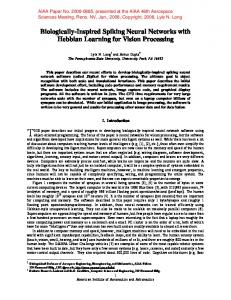
2.2.1 Static Behavior Figure 1 shows the spreading of a wave front in a workspace without obstacles: a)
b)
c)
Figure 1: Spreading of a wave front in a workspace without obstacles Figure 1a shows the workspace Ψ at time t when the target is activated to create a wave front. fig. 1b shows the initial wave front at time t+1, fig. 1c shows the front at time t+4. A wave front is a set of active points in the workspace Ψ. The activity of each point P ∈Ψ at a given time t is determined by the spreading rule: active( P, t ) := ¬obstacle( P) ∧ nhv _ active( P, t − 1) ∧ ¬active _ in( P, t , n) (spreading rule) with active( P, t ) : obstacle( P) :
true if P is active at time t true if P ∈Θ
nhv _ active( P, t ) : true if an immediate horizontal or vertical neighbor of P is active at time t. See text for details. : active _ in( P, t , n) true if P has been active at least once during t-1, ..., t-n
Horizontal or vertical neighbors of a point P within the meaning of nhv_active are the two immediate neighbors of P in the positive and negative direction of each coordinate-axis. So, in an N-dimensional workspace, P has 2 N horizontal or vertical neighbors.
target
start
obstacle
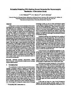
Figure 2: Two wave fronts in a workspace with an obstacle Figure 2 shows two wave fronts in a workspace with an obstacle. The front has reached a neighbor of the starting point S. A point P is added to the path Ω if it meets the path rule: path( P) := active( P) ∧ cursp _ neighbor ( P) ∧ ( P ≠ S ) where active( P, t ) :
(path rule)
true if P is active
cursp _ neighbor ( P) :true if an immediate neighbor of P is labeled as the current starting point
The last condition ( P ≠ S ) prevents, that the path is built beyond the target T. When a point P is added to the path, the label current starting point is moved to P. Only one point in the workspace can possess this label at a given time. Finally, to cut an existing path Ω at a given point P, we define a simple cutting action: CUT ( P), P ∈Ω : remove P and all following points from Ω (cutting rule) CUT ( P), P ∉Ω : do nothing The second part of the action for P ∉Ω must be defined to implement cutting noise (see below).
2.2.2 Dynamic Behavior To define a dynamic behavior for the radar pathfinder, we have to address three cases: • a movement of the starting point S, • a movement of the target point T and • a movement of an obstacle.
Movement of the starting point If the starting point S follows the existing path Ω, moving to a point S ′ ∈ Ω , we remove all points preceding S ′ from Ω. If S does not follow the path, i.e. if S ′ ∉ Ω we delete Ω completely by cutting it at S: S → S ′ , S ′ ∈ Ω : remove all points preceding S ′ from Ω S → S ′ , S ′ ∉ Ω : cut ( S ) Movement of the target point The spreading rule and the path rule guarantee that the path follows any movement of the target point T. But following a moving target, the length of the path can become suboptimal. There are two ways to address this problem: • Path length limitation In an application where a manipulator follows a path to reach a target point, the manipulator does not need to know the complete path if the distance to the target is long. It only must know the next l points of the path to plan its movements and to assure a jerk-free motion. In such an application, the maximum length of the path can be limited to a fixed size l by altering the path rule to: path( P) := active( P) ∧ cursp _ neighbor ( P) ∧ ( P ≠ S ) ∧ ( Ω < l ) • Using cutting noise A path can become suboptimally long either because a moving target has been followed or because obstacles have moved. Instead of developing complex algorithms to detect such a path and to fix it [12], a very easy solution can be used: noise. By cutting noise the cutting rule is applied to randomly selected points P ∈Ψ . A point P is selected with a very low probability α, e.g. α = 0.5%. By this a path is cut in random time intervals. From the cutting point it can then grow optimally according to the current position of the target point and the obstacles. Movement of an obstacle Two problems can arise when an obstacle moves: • The obstacle can move into the existing path giving Ω ∩ Θ ≠ ∅ To solve this problem the path is cut at all points P ∈( Ω ∩ Θ) : ∀P ∈( Ω ∩ Θ) : cut ( P) • The length of the path can become suboptimal. This problem is solved by using path length limitation or cutting noise (see above).
3
N EURONAL I MPLEMENTATION
Several features of the presented algorithm faciliate a neuronal implementation. The work space is spatially discret, and every point in space may be represented by a neuron. The parallism of neural networks can be exploited because computation and communication is only local. The state of a point in the work space or a neuron
depends only on its former state and the states of the immediate neighbors. A neuron only needs to exchange discret information: active or not. However, a neuron should have some notion of time, in order to remember wether it has been activated as member of a wave or a path. So, we choose spiking neurons as model neurons with dynamic behavior for our neuronal implementation. 3.1
Spiking Neurons
Spiking neurons are basically complex integrate-and-fire neurons [1] [2]. A general model for a spiking neuron is shown in figure 3: weights w(t) input spikes x(t)
h h
g f h
output spikes y(t)
Figure 3: General model of a spiking neuron The neurons communicate via spikes only. Incoming spikes x(t)∈{0, 1} are weighted and induce a time-varying potential at a synapse which changes according to an impulse response function h(t) on a time scale much longer than a single spike. A spiking neuron may have several synapses with different impulse response functions. The time course of h(t) models a postsynaptic potential and equips the neuron with a short term memory. This function may be composed of a sharp rise with a following exponential decay or it may be a solely decaying function. The combination function g accumulates various potentials by means of addition, subtraction and/or multiplication. This yields the membrane potential. The output function f finally compares the membrane potential with a firing threshold to determine whether to emit a spike y(t)∈{0, 1} to the connected neurons or not. The weights of a connection may be changed according to a appropriate learning rule. We choose Hebbian-learning, in which the weights between co-activated neurons are strengthened. A neuron is called to be target-learning-active when the membrane potential is actually greater than a learning threshold. A neuron is source-learningactive when it emits a spike. The weights are decayed when only the target or only the source neuron is learning-active. By this way we are able to learn a directed connection from a source to a target neuron when both neurons are simultanously learning-active. For our simulations we used a simulator for spike-processing neural networks with graphical user interface, called SimSPiNN [8], which we have developped because available neuro-simulators are not well suited for the simulation of spike-processing neural networks. In [9] and [10] we survey the relevant features that an efficient implementation of spike-processing neural networks should regard. For real-time simulation of very large-scale networks (N>100 000) we are currently developping a hardware accelerator, called NESPINN [11].
3.2
Neuronal Implementation of the Radar Path Planner
To implement the radar pathfinder using our neuron model, we need only two processing layers: • the spreading layer implementing the spreading rule and • the path layer implementing the path rule. Each point in the workspace has one corresponding neuron in the spreading layer and one in the path layer. Figure 4 shows a vertical cut through the spreading layer: P
T
P
O
T
P
O
T
P
O
T
O
Figure 4: Vertical cut through the spreading layer Each neuron is connected to its horizontal and vertical neighbors by an exitatory connection and to itself by an inhibitory connection. All connection have a delay value of 1 time step. When a neuron is active, i.e. when it spikes, it passes this spike to its horizontal and vertical neighbors. So, in the next time step each neighbor neuron becomes active if it is not currently self-inhibited. This way a wave front of active neurons spreads trough the spreading layer. The self-inhibition of the neurons is needed to prevent the wave from moving backward. Each spreading neuron has an inhibitory obstacle-point-input (O), by witch it is inhibited if it is part of an obstacle, and an exitatory target-point-input (T), by witch it can be activated periodically to create a wave. Each neuron in the spreading layer has a corresponding neuron in the path layer to which it is connected be an exitatory connection (P). start_in
target_in
learning source_activ source_inhib learning target_inhib spreading_in
Figure 5: Inputs and connections to the left neighbor of a neuron in the path layer
Each neuron in the path layer is connected to each of its eight neighbors with three connections, one permanent and two learning ones. In addition each neuron has three inputs. Figure shows the inputs and the connections to the left neighbors of a neuron in the path layer. Figure 6 is used to explain how the path layer works: a)
b) start_in
P
s_inhib
S
source_activ
P
s_inhib
start_in
S
target_inhib spreading_in
Figure 6: Origin of a path from S to P. a) before, b) after the connections are learned. An oriented connection is to be learned from the starting point S to the first point P of the path. To learn this connection, the corresponding neuron of S (neuron S) in the path layer must be source-learning active and simultaneously neuron P must be targetlearning active. Figure a shows the initial situation when no connection is learned yet. S gets a source-learning activation by a continual signal at its input start_in. The source activation leads also to a spike activation, so the neuron spikes continuously, passing a source-learning inhibition over the permanent connection s_inhib to P. Neuron P is not spiking, so the connection s_inhib from P to S has no effect yet. The wave front in the spreading layer has reached P, so neuron P gets a spike from its corresponding neuron in the spreading layer via its input spreading_in. This spike makes P target-learning active. Thus the learning connections source_activ and target_inhib from S to P are created. Via soure_activ P gets a permanent sourcelearning and spiking activation form the continuously spiking S. Via target_inhib a further target-learning activation of P is prevented. Via the permanent connection s_inhib from P to S the source-learning activation of S is canceled. So now, neuron P is source-learning active and continuously spiking. This is the same situation that we had before with neuron S. If the next wave front in the spreading layer reaches a neighbor Q of P, a path is built from P to Q. The input target_in is used to stop the building of the path at the neuron corresponding to the target point.
b)
a)
obstacle
obstacle
path
start
target
path
target start
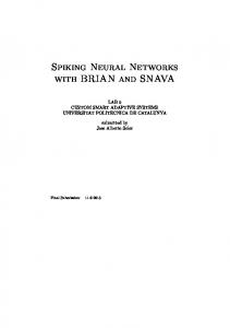
Figure 7: An example of two simulation frames with a moving target point and a moving obstacle Figure 7 shows an example of two successive simulation frames, in which the path planner displays the optimal path from the source point to the target point. When the source point, the target point or an obstacle moves a new optimal path is dynamically build as described in section 2. The path is cut and rebuild when an obstacle moves into the path. When a path becomes sub-optimal by a moving target point or obstacle, a new optimal path is found by path length limitation and cutting noise.
4
C ONCLUSION
In this paper we have presented a new path planning algorithm, the radar path planner. This path planner is capable of planning paths in unknown, partially known, and changing environments. A path is build in the following way: In regular intervals the target point sends out a wave front traversing the work space with constant speed. The neighbor point of the starting point that is first reached by the wave front must be part of an optimal path. This neighbor point becomes now the new starting point and the procedure is repeated until the target point is reached. When the source point, the target point or an obstacle moves a new optimal path is dynamically build. The path is cut and rebuild when an obstacle moves into the path. When a path becomes sub-optimal by a moving target point or obstacle, a new optimal path is found by path length limitation and cutting noise. Furthermore we have presented an efficient implementation of the path planner with spiking neurons. The features of the presented algorithm faciliate a neuronal implementation. We choose spiking neurons as model neurons with dynamic behavior for our neuronal implementation.
5
R EFERENCES
[1]
R. Eckhorn, H. J. Reitboeck, M. Arndt, P. Dicke, "Feature linking via stimulus-evoked oscillations: Experimental results from cat visual cortex and functional implication from a network model", Proc. ICNN I: 723-730, 1989.
[2]
W. Gerstner, R. Ritz, J. L. van Hemmen, "A biologically motivated and analytically soluble model of collective oscillations in the cortex", Biol. Cybern. 68: 363-374, 1993. [3] C. M. Gray, W. Singer, "Stimulus-specific neuronal oscillations in orientation columns of cat visual cortex", Proc. Natl. Acad. Sci. USA 86: 1698-1702, 1989 [4] J.-C. Latombe, "Robot Motion Planning", Boston, Kluwer, 1991. [5] K. Kant, S. Zucker, "Towards efficient trajectory planning,: The path-velocity decomposition", Int. J. Robotics Research, 5: 72-89, 1986. [6] V.J. Lumelsky, A.A. Stepanow,"Dynamic Path Planning for a Mobile Automaton with Limited Information on the Environment", IEEE Trans. Automatic Control, 32(11): 1058-1063. [7] R. Glasius, A. Komoda, S. Gielen,"Neural Network Dynamics for Path Planning and Obstacle Avoidance", Neural Networks, 8(1): 125-133, 1995. [8] M. Walker, H. Wang, S. Kartamihardjo, U. Roth, "SimSPiNN - A Simulator for SpikeProcessing Neural Networks", submitted to IMACS 97. [9] U. Roth, A. Jahnke, H. Klar, "Hardware Requirements for Spike-Processing Neural Net works", Proc. IWANN´95, 720-727, 1995. [10] A. Jahnke, U. Roth, H. Klar, “How to Simulate Spike-Processing Neural Networks“, submitted to ESANN 97. [11] A. Jahnke, U. Roth, H. Klar: "A SIMD/Dataflow Architecture for a Neurocomputer for Spike-Processing Neural Networks (NESPINN)", MicroNeuro'96, 232-237, 1996. [12] A. Stentz, "Optimal and Efficient Path Planning for Unknown and Dynamic Environments", Int. J. Robotics and Automation, 10(3): 89-100, 1995.