Spiking Neural Building Block Robot with Hebbian ... - Semantic Scholar
Recommend Documents
A correlation-based ''Hebbian'' learning rule at a spike level with millisecond resolution is formulated ... aptic neurons leads to an evolution of neuronal receptive.Missing:
Architecture of the Weight-Unit of NESPINN. Ulrich Roth, Axel Jahnke, and Heinrich Klar. Institut für Mikroelektronik, Technische Universität Berlin. Jebensstr.1 ...
Email: [email protected] ... fired in a particular layer was used as a code. ..... [14] D. I. Perrett, E. T. Rolls, and W. Caan, âVisual neurons responsive to faces in ...
spent processing. However, for short life-time applica- tions, learning time may dominate the entire life span. On-chip learning is also a very useful when a fast ...
software development effort, including code performance and memory requirement results. The software includes the neural network, image capture code, and graphical display programs. All the ...... 2004: Roberts and Company. 12. Felleman ...
Having two spikes inside, neuron rl10 i fires at step t ? 3 and sends one spike to neurons rl9 i and rlj . At the same step, neuron rl8 i sends an anti-spike neuron.
ABSTRACT: The path planning problem is relevant for all applications in ..... Each spreading neuron has an inhibitory obstacle-point-input (O), by witch it is.
lateral links feedback links. 4Ã1Ã8. 8Ã2Ã4. 16Ã4Ã2. Figure 1: Sketch of the Neural Abstraction Pyramid. approach to image interpretation [3] offers an even more ...
experiments, is studied via an integrate-and-fire model with realistic dynamics. ... interact in a competitive, suppressive fashion, which is not the case when the ...
Suppose it starts off in corner c1. As the robot doesn't know what the next corner from c1 is, it starts wall following. After travelling a certain distance, its front ...
Sep 23, 2006 - of undergraduates from the University of North Dakota Computer .... The three robot platforms were an ActivMedia Pioneer I with a laptop (Figure 4 (a)), ..... Each year we tried to have the robot sense the pink robbons and ...
question is how to build a map while simultaneously using that map to self-localize. We have addressed this question with ARIEL (Autonomous Robot for ...
Louis-Jean Boë, Barbara Davis, Chris Matyear, Emmanuel Mazer and ... G. Venturini (Eds.), ICML'96 Workshop on Evolutionary Computing and Machine.
interconnected neurons making up the central nervous systems in living creatures. .... signed neuron model and network architecture, are strongly restrictive ...
the constraints of neuromorphic hardware currently being de- veloped, including
the DARPA SyNAPSE neuromorphic chips for very low power spiking model ...
Nov 6, 2015 - BRIAN is a framework for simulating Spiking. Neural Networks built entirely in Python language. It is programmed with ease of use in mind.
May 2, 2014 - AN OPTIMIZATION SPIKING NEURAL P SYSTEM .... hardware/software implementation,41,65 and wide applications.11,27,45,69. The most ...
to obtain the same level of parallelization and performance. [10]. Another ..... to be concatenated, checked on (if they conform to the form. (b-3) for ... vector Python list variable conf V ec, in this case if .... sible and valid string, the string
Mar 3, 2015 - known as partially observable reinforcement learning (PORL) problems. It provides a gener- ... Free Reinforcement Learning with High-Dimensional. Sensory Input and ...... (A) Illustration of the task. The agent starts at the ...
May 2, 2014 - De Montfort University, Leicester, UK [email protected]. MARIO J. PÃREZ-JIMÃNEZ. Department of Computer Science and Artificial Intelligence.
Nov 24, 2010 - Butts et al., 2007; Hromádka et al., 2008; Haider et al., 2010). ...... DeWeese MR, Zador AM (2006) Non-Gaussian membrane potential dy-.
In the FSN P system, two types of neurons (fuzzy proposition neuron and fuzzy rule neuron), certain factor and new spiking rule are considered, and content.
Jun 28, 2017 - Passâ (OP). For the rest of the paper we will be distinguishing between SBS (zero leakage) and OP (non-zero leakage) setups, for both training ...
Aug 9, 2013 - system such as spiking neural network. Section IV introduces the idea of learning in population of networks. Sec. V presents validation of the ...
Spiking Neural Building Block Robot with Hebbian ... - Semantic Scholar
figure 9D a bright flashlight is being held in front of the light sensor resulting in a maximum frequency spike train which immediately starts adapting towards its ...
In Proceedings of IEEE International Conference on Intelligent Robots and Systems (IROS2003),IEEE Press Las Vegas, Nevada, October 27 - 31, 2003
Spiking Neural Building Block Robot with Hebbian Learning J. Nielsen
The Adaptronics Group, The Maersk Institute, University of Southern Denmark Campusvej 55, DK-5230 Odense M, Denmark www.adaptronics.dk Abstract We developed spiking neural network control for a modular robotic system. The modular robotic system can be easily assembled by a user who is allowed to make overall behaviors by assembling the physical structure made up of a number of modules. The control of each module (building block) is implemented as a spiking neuron and action potentials are sent through the communication channels of the building blocks. We show how to make a mobile robot with these spiking neural building blocks. Hebbian learning is then applied to the spiking neuron building blocks in order to allow the mobile robot to adapt to changing environmental conditions. Collected data shows the learning process, sensor adaptation and performance on a simple task for the mobile robot made out of spiking neural building blocks.
1
Introduction
In many cases, the development of robot behaviors happens through manipulation of the control, e.g. by programming the robot in a traditional programming language. Here, we want to investigate an alternative to development of control in isolation. Namely, we suggest allowing development of robot behaviors by the physical manipulation of the robot morphology in combination with training of control. In order to facilitate this investigation, we used a new kind of artifacts called intelligent artifacts. The intelligent artifacts can be viewed as a modular robotic system. These artifacts consist of a number of building blocks with individual processing and communication [4, 5]. By assembling the building blocks into a structure, the user can develop both physical and functional structures. Hence, the user can be programming a behavior of the system by building a physical structure. Some building blocks can be pure processing units, whereas other can include actuation or sensing. The processing in the individual building block can be arithmetic operations, behaviors in a behavior-based system, or similar. Here, the processing in the form of ar-
tificial spiking neurons is introduced. Each building block is viewed as a spiking neuron and the connections between building blocks can send action potentials. By attaching building blocks together, it is possible to make physical, artificial spiking neural networks. For simplicity, in the implementation presented here, each building block is therefore considered a spiking neuron with two predefined inputs and two predefined outputs.
2
Hardware Building Blocks
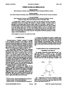
We constructed a number of hardware building blocks with individual processing power and communication capabilities. In order to exemplify in a clear manner how these function as building blocks, we chose to implement them in LEGO DUPLO housing. Connections are put in the center of each 2*2 area on the top and on the bottom of the DUPLO bricks. So each building block has two connectors on the top (one on the left and one on the right) and two connectors on the bottom (figure 1). Each building block contains a PIC micro controller, in this case a PIC16F876 40-pin 8 bit CMOS Flash micro controller (figure 1). Further, each block contains four serial two-way connections. We developed a number of standard electronic building blocks that allow processing and serial communication, and some specialised building-blocks that in-
Figure 1: The hardware of a building block.
25
Membrane potential (mV) 25
Membrane potential
0 mV
Overshoot
Resting potential
0 −60
Rising phase
Repolarization After−hyperpolarization
10
Stimulus intensity
Threshold −60 Resting level 0
1
0
2
3
4
Time(ms)
0
2
4
6
8
10
12
14
16
18
20
Seconds
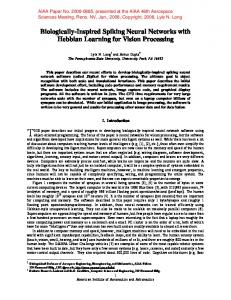
Figure 2: The action potential. With inspiration from [6].
Figure 3: Sensory nerve activity with different stimulus intensities and durations. With inspiration from [6].
clude sensors (e.g. LDR, IR, microphones, touch) or output functionality (e.g. motor, LEDs, sound, display) – see [4] for details. With these building blocks, it is possible to construct a huge variety of physical objects with various functionalities. The processing in the physical construction is distributed among all the building blocks, and there is no central control opposed to traditional computerised systems (e.g. traditional robots). The distribution of control is obtained by allowing processing within each individual building block. We can therefore imagine the processing to be as neural networks [5] or as spiking neural networks as described in the following. Here, sensory building blocks can represent input neurons, output building blocks can represent output neurons, and standard building blocks can represent hidden neurons.
3
Spiking Neurons
Real neurons are, with a few exceptions, all spiking neurons. The neuron pathways in general start at the sensors, which means that the series of action potentials generated throughout the network of connected neurons usually starts as sensory input and in most cases ends up at the actuators (muscular fibres). The shape of an action potential can be seen in figure 2, where the membrane potential is building up from its resting level towards the activation threshold due to presynaptic activity. Hereafter the potential rises steeply and overshoots 0 mV with approximately 25 mV. Then the repolarization phase is entered and the action potential undershoots the resting level in the hyperpolarization phase. Another action potential will under normal circumstances be generated at some point after the after-hyperpolarization phase when the resting level of the membrane potential has been reached again. It is, however, possible to generate an action potential in the after-hyperpolarization phase, but the neuron will need a higher amount of input than when it is at its resting level in order to fire an action potential [6]. The way neuro-sensors encode the strength of their applied physical stimuli is shown in figure 3. The physical
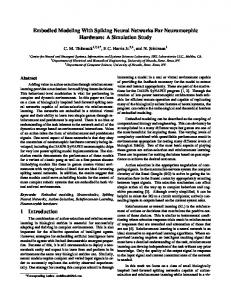
Figure 4: Sensor Adaptation in a sensory receptor is often related to a decline in the generator potential with time. A) No decline, B) Slow decline, C) Rapid decline. With inspiration from [6].
stimuli intensity is frequency modulated via the rate of the action potentials. However, the generator potential has to be higher than the activation threshold for action potentials to be generated at all. Another issue in the neuro-sensors is adaptation, which is related to the generator potential of the sensor. With no adaptation, the generator potential remains the same when a constant stimulus is applied. With adaptation the generator potential declines over time either slowly or rapidly dependent on the type of sensor nerve. These principles are all shown in figure 4. Adaptation is used in the central nervous system to avoid ”sensory overload” and it allows less important or unchanging environmental stimuli to be partially ignored. Rapid adaptation is also important in sensory systems, where the rate of change is important. When a change occurs in the sensor stimulus, the phasic response will occur again reproducing the generator potential curves shown above, just at other potential values.
4
Hebbian Learning
D. Hebb formulated in 1949 a fundamental principle of learning [3]: When an axon of cell A is near enough to excite a cell B and repeatedly or persistently takes part in firing it, some growth process or metabolic change takes place in one or both cells such that A’s efficiency, as one of the cells firing B is increased. In standard neural network theory this rule is described as an adaptation rule where a synapse is strengthened if preand postsynaptic neurons are active at ’the same time’. When speaking of spiking neural networks, the meaning of ’the same time’ must however be specified. Due to the time it takes for a neuron to build up towards its threshold level one has to introduce a time window to find out which presynaptic neurons take part in firing this neuron [2]. Hebbian learning is a so-called unsupervised learning method and when formulated as a spike learning method the process of learning is driven by the temporal correlations between presynaptic spike arrival and postsynaptic firing.
the steady state level of the adaptation will be higher than when adapting to lower level sensory input. In this way sensory inputs of different values can still be distinguished although adaptation has taken place. The current values for adaptation have been preset to take around 2 seconds for adapting from a change from total darkness into daylight. The curves for adaptation are exponential as shown in figure 4B,C. Given the limitations of only four communication channels per intelligent building block, the threshold values has been preprogrammed at a fairly high level so that input from only one building block is enough to generate output action potentials given that the input frequency is high enough to allow for temporal summation. Hebbian learning has been implemented in the CPUblocks and has been programmed to stimulate connections at a certain learning rate. This rate has been set fairly high (connection strengths updated every 2 seconds) in order to speed up the learning process. Besides, whenever an action potential is fired the input activity of the last 10ms is traced back to the actual input port to determine which connections to strengthen.
6 5
Implementation Issues
The implementation of spiking neurons in the intelligent artifacts uses the hardware (a PIC16F876 processor), where the action potentials emitted are digital pulses. In order to support both excitatory and inhibitory signals, these are coded to be of different lengths. The generation of action potentials is based on the input of the neurons via a leaky integrator, which sums up the amount of input while decaying at a certain rate: A(t) = α × A(t − 1) + I(t), 0 < α < 1
(1)
where A(t) is the activation function, I(t) is the input and a is the decay rate. The activation function is a simple threshold-function which sends an action potential when the summed input reaches above a given threshold. An implementation of absolute and relative refractory period has also been investigated, where the absolute refractory period decides the maximum action potential frequency of a neuron, while the relative refractory period demands higher input in order for the neuron to generate action potentials. The current implementation has an absolute refractory period of about 10ms, which reflects the refractory period of biologic neurons very well. Another thing that has been investigated and implemented is adaptation in the sensors based on the theory described in the previous section. Here the adaptation is made so that when adapting to high levels of sensory input
Experiments
In order to verify that the spiking neural building blocks can be used to make robotic systems, we made an experiment where the structure should learn to control a mobile robot to perform a light seeking task. Learning happened by allowing a user to show light (e.g. with a flash light) to the robot construction over a period of approximately 35 minutes while the building blocks would perform sensor adaptation and Hebbian learning.
6.1 Test Platform and Scenario The scenario for the testing of the building blocks has been selected so as to demonstrate some of the capabilities of the intelligent artifacts implemented as spiking neurons. The testing takes place within a 150x150cm no-wallsarea where a mobile robot is to trace and approach a light source using a structure of assembled spiking neural building blocks. The light source is placed in the middle of the field 10 centimeters away from the borderline furthest away from a camera. An example of the scenario can be seen in figure 5. The blocks used for solving the light tracing task are the battery block, the LDR-sensor block, the CPU block and the LEGO-motor controller block shown in figure 6. The battery block supplies the final structure through the individual power sharing capabilities of the blocks. The LDR-sensor block is light-sensitive sensory block that uses the above mentioned theory to modulate light levels into
Light Source
LDR 1 Sensory Neuron
LDR 2 Sensory Neuron
Spike train 1
Spike train 2
N1
N2 Hebbian Learning Neurons
Motor Neuron 2
Motor Neuron 1
Figure 5: The test scenario.
PWM Signal
PWM Signal Motor 1
frequency based pulse trains while adapting to light levels over time. It should be mentioned that even though there are two LDR-sensors on this block only input from the one is used to generate the output spike trains. The CPU-block implements the spiking neural model described above including stimulation of connection weights due to output resultant input over time using the rules of Hebbian learning. Finally, the LEGO-motor controller block converts the input spike trains into motor PWM-signals used to control standard LEGO motors.
Motor 2
Motor Driver 1 1
Motor Driver 2 2
Neuron Brick 1 4
LDR Sensor 1
3
2
1
Neuron Brick 2 3
4
LDR Sensor 2
Figure 7: The built structure in two schematic views and as a photo.
Figure 6: The four kinds of blocks used for the light tracing task. The actual assembly of the blocks models a Braitenberg vehicle [1] where the left light sensor ends up controlling the right motor and vice versa. Two schematics of the connection can be seen in figure 7 where the first is a neural connection diagram that shows how the sensory input ends up controlling the motor due to the spike trains travelling through the structure. The second part of figure 7 shows how all the blocks are connected to form the control structure for the vehicle.
6.2 Data Collection Techniques In order to document the path of the vehicle in the test scenario, a video camera and a standard picture transformation technique has been used to transform pictures like the one shown in figure 5 into pictures seen from above. In
order to do this transformation, the objects that are going to be traced have to be in the same planar level, so compared to figure 5 the blue DUPLO brick on the top of the vehicle is at the same vertical level as the white bricks on top of the four corner towers that make up the borders of the test scenario. In this way each test of the vehicle is done within this area and the result is recorded on a digital video camera. Afterwards the video sequences of the individual tests are transferred to a computer where every 25 frame is stored as a picture giving a picture for each whole second of the test. Each of these pictures are then transformed using the before mentioned technique and the blue DUPLO brick on the top of the vehicle is traced with a color tracking routine to give the specific coordinates of the vehicle within the 150x150cm test area. Another issue in this example is to measure the actual functionality of the blocks used. As the only output from the blocks are their spike sequences, these have been recorded on a digital oscilloscope (Tektronix TDS320) to demonstrate both the adaptive features of the LDR-sensor block as well as the learning capabilities of the CPU-block.
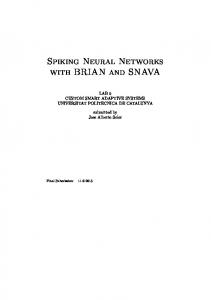
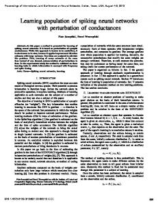
The next series of test results, shown in figure 9, displays the output of the LDR-sensor block with the built-in adaptive spiking neuron. Figure 9A,B,C show how the sensor adapts to normal office ambient light brightness. In figure 9A the block has been kept under total darkness for a while and then suddenly put into the light resulting in a maximum frequency spike train. After a short time, figure
The results of the tests are described in the following considering both the built structure as well as the functionality of the single block. Figure 8 shows results of 8 test runs in the same scenario. In each of the test runs, the vehicle has been placed at an angle less or equal to 45 degrees towards the light. Each test of figure 8 will be described in the following starting with the top leftmost figure. The vehicle has been fully trained before starting the test session which means that it is just about unable to generate enough spikes for the motors to drive under the present ambient lighting conditions. This means that it has to have a brighter light source within its field of vision in order to drive the motors forward. In the first test the vehicle starts at angle 0 to the light source driving straight towards the goal, and due to little differences in the lightning conditions as well as the the motor forces the vehicle slides of to the right slowly until the right light sensor goes outside of the light cone slowing down the left motor and finally making the vehicle reach its destination. Because of the adaptation in the light sensors, the vehicle reacts fast over a short period time and through a longer period of time the reaction flattens out. Because of this fact, in the next test the vehicle does not reach its goal. Here the vehicle is started at an angle approximately 45 degrees to the light source and because of the fact that the vehicle is a little bit of to the right as in the previous test, it ends up crossing the light cone so far away from the light source that the edge between the light cone and the surroundings is just blurry enough to make the vehicle drive through it without adjusting the vehicle direction enough to keep one light sensor inside the light cone. As can be seen the result in the next figure is almost identical to this result. In the rest of the figures the vehicle reaches the goal but in two of the cases it has to go through a loop to get there. The loops are possible because of the before mentioned different powers of the motors meaning that one motor might be just able to drive forwards under the ambient lighting conditions while the other motor is standing still. This results in loops are made even though the light source is not within the line of sight of either of the sensors. It can also be seen that it is the vehicle’s right motor that drives under ambient lighting conditions because of the fact that both of the loops are going counter-clockwise.
Figure 8: 8 different runs in the test scenario. Some points of measurement are outside the actual path of the vehicle. These are due to the vision program finding blue spots in the picture which are not a part of the blue DUPLO brick. Besides there are also missing points along the paths where the lighting conditions have made it impossible for the vision program to detect the blue DUPLO brick.
9B, the sensor has adapted further to the brightness of the ambient light and finally in the figure 9C the adaptation has reached its steady state resulting in a somewhat lower frequency spike train than those in A and B. Now, in figure 9D a bright flashlight is being held in front of the light sensor resulting in a maximum frequency spike train which immediately starts adapting towards its steady state in figure 9F. It should be noted that the steady states of the
(A)
(B)
(A)
(B)
(C)
(D)
(C)
(D)
(E)
(F)
(E)
(F)
(G)
(H)
Figure 9: Visualization of the sensor adaptation.
ambient light (figure 9C) and the bright flashlight (figure 9F) are not the same and that brighter light still results in a higher spike frequency although adaptation has been introduced. The last measurement that has been done is the learning capabilities of the CPU-block. In these measurements the CPU-block gets its input from the LDR-block just as in the vehicle described above. The outputs of both of these blocks are displayed in the picture sequence of figure 10. Here the upper channel of the oscilloscope pictures shows the output of the sensory neuron and the lower shows the output of the learning neuron. The learning starts at point zero (figure 10A), where the sensor is kept under normal office lighting conditions. To start the learning a bright light source is introduced to the light sensor and this in turn generates a fast series of spikes which just overcomes the threshold of the learning neuron making it send out spikes, although at a lower frequency (figure 10B). During this process the connection to the light sensor is strengthened which results in that after the light is turned off and back on a couple of times the learning neuron now sends out spikes at increasingly higher frequencies (figure 10C-D). At figure 10E, however, it can be seen that the
(I)
Figure 10: Visualization of the learning process.
learning has not been going on for long enough for the learning neuron to send out spikes when the sensory neuron is exposed just to ambient light so the learning process continues. In figure 10G the learning neuron starts to react to light brightness just a little above ambient conditions and
being exposed to this kind of light for some time it starts to reflect the frequencies of the light sensor neuron with just a slight delay. This can be seen in the last two pictures, figure 10H,I.
7
Discussion and Conclusion
Here, we developed spiking neural network control for a modular robotic system (the intelligent artifacts). The design of the hardware building blocks made an implementation of neural networks and spiking neural networks straight forward, since the building blocks allow individual processing and communication, and the overall behavior emerges from the assembly of the individual building blocks into one, connected structure. Here, we showed that it is possible to make a simple, mobile robot with these spiking neural building blocks. However, one should keep in mind that this is just one example, and that the building blocks are by no means limited to the construction of mobile robots. Including other input and output building blocks, we have made numerous other constructions (sound generator, arithmetic expression, growing ’tree’, etc.) – it would be very limiting to view the possibilities as being only in the field of mobile robotics! We also showed that Hebbian learning can be applied to the spiking neuron building blocks in order to allow the system to adapt to changing environmental conditions. Also, sensor adaptation could happen in a fairly easy manner. This indicate that it (at least in some cases) is possible to allow a user to physically construct a robot with the building blocks and afterwards train the robot to learn some task without any use of a traditional computer, a simulator, or similar. Therefore, we believe that the presented concept may hold great promises for the development of such a new kind of robotic systems in the future.
Acknowledgement This work is partly sponsored by the Danish National Research Council project ”Intelligent Artifacts” and the EU Future and Emergent Technology project ”HYDRA” (http://www.hydra-robot.com).
References [1] V. Braitenberg. Vehicles: Experiments in Synthetic Psychology. MIT Press, MA, 1984. [2] W. Gerstner, R. Kempter, J. L. van Hemmen, and H. Wagner. Hebbian learning of pulse timing in the barn owl auditory system. In Wolfgang Maass and Cristopher M. Bishop, editors, Pulsed Neural Networks. MIT Press, 2001. [3] D. O. Hebb. The Organization of Behavior. Wiley, New York, 1949.
[4] H. H. Lund. Intelligent artefacts. In Sugisaka and Tanaka, editors, Proceedings of 8th International Symposium on Artificial Life and Robotics. ISAROB, Oita, 2003. [5] H. H. Lund. Neural building blocks. In 1st International IEEE EMB Conference on Neural Engineering, Capri, Italy, March 20-22 2003. IEEE Press. [6] R. A. Rhoades and G. A. Tanner. Medical Physiology. Lippincott Williams & Wilkins, 1995.