International Journal of ChemTech Research CODEN( USA): IJCRGG ISSN : 0974-4290 Vol.5, No.2, pp 980-992, April-June 2013
ICGSEE-2013[14th – 16th March 2013] International Conference on Global Scenario in Environment and Energy
Dynamic Performance Of DFIG Based WECS Under Different Voltage Sag Rishabh Dev Shukla, R. K. Tripathi*, Deptt. of electrical engineering, Motilal Nehru National Institute of Technology, Allahabad-211004, India.
*Corres.author:
[email protected]
Abstract: At the present time Doubly Fed Induction Generator (DFIG) based wind energy conversion systems are widely used for large wind power plants. DFIG offers many advantages for instance reduced rating power converter, low cost and reduced losses with the better efficiency, easy in realization of power factor correction schemes, variable speed operation and four quadrants active and reactive power control capabilities. Due to operate under variable speed mode total energy output is much more, so capacity utilization factor is enhanced and cost of per unit energy is cheap. But the main disadvantage of DFIG is that it is very susceptible to grid disturbance or fault, particularly for the voltage dip. As the doubly-fed induction generator (DFIG) has been broadly used in wind energy conversion systems, the Fault Ride through (FRT) or Low Voltage Ride through (LVRT) expertise of the DFIG has been investigated extensively in recent times. This paper focuses the fault ride-through capability of DFIG based WECSs under different voltage sag. The paper also gives an overview on the interaction between variable-speed DFIG based WECSs and the power system subjected to disturbances/fault. The dynamic performance of WECS based on DFIG under grid faults is simulated and assessed. This paper also discusses major grid problems and grid codes for operation & grid connection of wind farms and gives brief introduction about the solutions for FRT/LVRT available in market today. Key words: DFIG, FRT, RSC, GSC, FRT/LVRT, WECS.
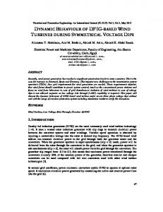
I Introduction As the diffusion of wind powers increases, Wind Turbines (WT) are required to remain connected for the duration of grid fault and add to system stability according to the modern grid codes. As the doubly-fed induction generator (DFIG) has been widely used in wind energy conversion systems, the fault ride through (FRT) technology of the DFIG has been investigated comprehensively in recent times. A block diagram of a DFIG based wind energy conversion system is illustrated in Fig.1. It consists of a wind turbine, a gearbox, a doubly-fed induction generator (DFIG) a Grid Side Converter (GSC) and a Rotor Side Converter (RSC). By controlling the RSC and GSC, the DFIG characteristics can be accustomed so as to achieve maximum of effective power translation or capturing capability for a wind turbine and to control its power generation with a lesser amount of fluctuation. Generally, power converters are controlled via vector control techniques, which give decoupled control of both active and reactive power.
R.K.Tripathi et al/Int.J.ChemTech Res.2013,5(2)
981
Fig. 1. Diagram of DFIG Based WECS
In usual operation the intend of the RSC is to control separately the active and reactive power on the grid, whereas the GSC has to keep the dc-link voltage at a set value in spite of the magnitude and the direction of the rotor power flow and to assurance a converter operation with unity power factor. DFIG based WECS are very susceptible to grid disturbances/faults, especially to voltage dips4. The abrupt drop of the grid voltage produces over-voltages & over-currents in the rotor windings that could even destroy the rotor side converter. At first, the solution implemented by the manufacturers to protect the converter was to short circuit the rotor windings via crowbar and disconnect the turbine from the grid5. Therefore, the wind turbines are not able to support in resuming normal operation of the grid. Moreover they add to increase the dip as they stop generating electrical power. Since the number of grid-connected turbines increases, this influence has become more important to investigate. A detailed theoretical analysis is given in7 for describing the growth of magnetic and electric variables of the DFIG during a voltage dip. In this analysis, the magnetic flux of the machine is separated into two parts.
Fig.2. (a) Decomposition of the flux at the beginning of the dip (b) development of the flux during the voltage dip.
The 1st part corresponds to the “forced flux” that rotates at synchronous speed & is associated with the stator voltage. The 2nd part is the “natural flux” that only appears in voltage transients. The natural flux does not rotate and is due to the strong over-voltages in the rotor. If the rotor side converter is not able to deal with these voltages, they will produce over-currents in the stator and the rotor of the generator and accordingly damaged the RSC, the controllers for generator/rotor side and grid side converters work alongside to meet the fault ridethrough requirement by storing the active power surplus in the inertia of the generator and maintaining the dclink voltage constant. In this paper, the dynamic response of a DFIG under grid voltage dip is analyzed via software simulation in Matlab/Simulink. This paper also discusses major grid problems and grid codes for operation and grid connection of wind farms.
II. Main Grid Problems & Grid Codes Numerous concepts have been projected for studying the behavior of DFIG based WECS connected to the grid. With the growth of wind power; the interaction between WECS and gird will cause new troubles regarding the safe and reliable operation of systems. High diffusion of intermittent wind power may affect the network in the following terms link1-4: Poor grid stability; Low-frequency operation; Impact of low power factor; Power flow;
R.K.Tripathi et al/Int.J.ChemTech Res.2013,5(2)
982
Short circuit; Power Quality. In general, the grid codes for wind deal with the technical requirements. The major requirements of typical grid codes for operation and grid connection of wind turbines are summarized in2 : Voltage operating range: For wind turbines (WT), it is required to operate within typical grid voltage variations. For safe and reliable operation of the grid, the Operational voltage limits of the wind farms Voltage (kV) should be within the range as specified by authority. Frequency operating range: The WTs are desired to operate within typical grid frequency variations. Frequency tolerance range is 47.5 to 51.5 Hz. Beyond this, the tolerance range is specified by the manufacturer. It is able to withstand change in frequency up to 0.5 Hz/sec. Active power control: The ability of the WT generators to regulate the active power output of the wind turbine according to system requirement. It is used to certify a stable frequency in the system, to avoid overloading of transmission lines, to stay away from large voltage steps and in-rush currents in start up and shut down of WTs. Frequency control: It is desired that wind farms to provide frequency regulation capability to assist for maintaining the desired network frequency. The system frequency is a principal indicator of the power balance in the system. Voltage & Reactive power control: Grid codes require that individual wind turbines control their own terminal voltage to a constant value by means of an automatic voltage regulator and provide dynamic reactive power control capability to maintain the reactive power balance and the power factor in the desired range. The wind farm should maintain a power factor of 0.95 lagging to 0.95 leading. High voltage ride through (HVRT): In the occasion that voltage goes above its higher limit value, the WTs should be able to stay on line for a given length of time. Low voltage/Fault ride through (LVRT/FRT): In the occurrence of voltage sag, the WTs are required to stay connected for a specific amount of time before being allowed to disconnect Fig. 3. Additionally, a number of utilities need that the WTs assist the grid voltage during faults. The time of fault or low voltage ride through depends on the amplitude of voltage drop at the Point of Common Coupling (PCC) during the fault and time taken by the grid system to recover to the normal state.
Vf : 15% of nominal system voltage Vpf: Minimum Voltage for normal operation of the wind turbine. The typical duration is 0.15 s,
Fig. 3. LVRT Curve
Power Quality Wind farms are required to make available the electric power with a desired quality. Capability of a wind farm, to operate loads without damaging or disturbing them & with no reducing the efficiency of the system. Wind farm modeling and verification Grid codes require wind farm owners/developers to give models and system data, to facilitate the system operator to examine by simulations the interface between the wind farm and the power system.
R.K.Tripathi et al/Int.J.ChemTech Res.2013,5(2)
983
Communications and external control The wind farm operators are required to give signals corresponding to a number of parameters important for the system operator to enable proper operation of the power system. Moreover, it must be possible to connect and disconnect the wind turbines remotely.
III. Dfig Modeling & Control In DFIG based variable-speed WECSs, the power electronic converter only has to handle a fraction (20–30%) of the total power5,6. This means that the losses in the power electronic converter can be reduced compared to a system where the converter has to handle the total power. In addition, the cost of the converter becomes lower. The stator circuit of the DFIG is connected to the grid while the rotor circuit is connected to a converter via slip rings.
Fig. 4. Mathematical model of DFIG
Mathematical model of DFIG The equivalent circuit of a DFIG in an synchronous reference frame rotating at angular speed shown in 5,6 Fig.4 . The stator and rotor voltages and in the synchronous reference frame can be expressed as, (1) (2) Where, flux linkages (3) (4) Control of Rotor Side Converter (RSC) The active and reactive powers which are delivered from the DFIG to the grid are controlled by means of controlling the rotor currents of the DFIG5-8. The two controllers in the rotor side controller determine inverter d- and q- axis voltages by comparing the d and q current set points to the actual d and q rotor current Fig.5.
Fig.5. DFIG Rotor side controller
R.K.Tripathi et al/Int.J.ChemTech Res.2013,5(2)
984
In Stator Voltage Orientation (SVO), neglecting the stator resistive voltage drop, the active and reactive powers of the stator and rotor are expressed as eq. (5, 6, 7 & 8), (5) (6) (7) (8) From the above equations, it is clear that power fed to the grid can be controlled by controlling the rotor current’s components. The rotor current components can be controlled by the vector control technique. Control of grid side converter (GSC) The purpose of the grid-side converter is to keep the DC link voltage constant irrespective of the direction of the rotor power flow. In order to maintain the DC link voltage constant, a bidirectional converter is required to implement in the rotor side circuit. Below the synchronous speed this converter work as a rectifier and above synchronous speed this converter works as an inverter to supply all generated power to the grid at a constant DC link voltage.
Fig. 6. DFIG Grid side controller
The grid side converter typically regulates DC voltage and reactive power. It is also a two stage controller operating in a grid AC voltage reference frame. The two controllers in the grid side controller determine inverter d-and q-axis voltages by comparing the d and q-current set points to the actual d and q- currents to the grid 9-11 Fig.6 .
IV. Simulation & Results Turbine data:
Table I: Specification Data DFIG data:
Turbine Power = 9 MW Rated power = 5MW Maximum output power = 10 MW Cut-in wind speed = 4 m/s Rated wind speed = 12 m/s Cut out wind speed = 18 m/s Type = 3 bladed, Upwind/Horizontal axis Rotor diameter = 82 m Rotational speed at rated power = 15.6-18.4 rpm Swept area = 22.89 m2 Tower height =27 m Wind energy utilization ratio (Cp) = 0.48
Rated power = 9 MW Voltage (line to line) = 575 V No. of Poles = 6 Frequency (f) = 60 Hz Stator resistance (Rs) = 0.00706 pu Rotor resistance (Rr) =0.005 pu Stator leakage inductance (Ls) = 0.171 pu Rotor leakage inductance (Lr) =0.156 pu Magnetizing inductance (Lm) = 2.9 pu
R.K.Tripathi et al/Int.J.ChemTech Res.2013,5(2)
985
For the purpose of studying the dynamic performance of DFIG wind turbine under normal and faulty condition with the SVO vector control scheme extensive simulation using MATLAB/SIMULINK have been performed. The turbine has the following specifications: Simulation Configuration of the DFIG Based Wind Turbine under Three-Phase Grid Fault:
Fig. 7. Simulation block diagram of DFIG based WECS under Three Phase Fault
Using the MATLAB/SIMULINK the above model [Fig.7] is used to simulate under the three phase short circuit current in voltage dip situation. When three phase fault occurs at 25KV Bus, the voltage sag at 575V will depend on the percentage impedance drop of DFIG. Using the MATLAB/SIMULINK the above model is used to simulate under the three phase short circuit current in voltage dip situation. When three phase fault occurs at 25KV Bus, the voltage sag at 575V will depend on the percentage impedance drop of DFIG.
Simulation Results Case1. Wind Turbine DFIG with normal condition
Fig. 8. At Bus 575V under normal condition Voltage
Fig. 9. At Bus 25KV under normal condition Voltage
R.K.Tripathi et al/Int.J.ChemTech Res.2013,5(2)
Fig. 10. Under normal condition Rotor Speed
Fig. 11. Under normal condition DC link Voltage
Fig. 12. Under normal condition Total Active Power
Fig. 13. under normal condition Reactive Power
986
R.K.Tripathi et al/Int.J.ChemTech Res.2013,5(2)
987
Fig. 14. Rotor Active Power under normal condition
From the above results shown [Fig.8 to Fig.14] it is cleared that under normal condition, power flow is approximately 70 to 80% through the stator and 20 to 30% through the rotor. The DFIG wind turbine produces around 4.9 MW active power, corresponding to 12 m/s wind speed. By using the stator voltage orientation rotor side vector control scheme, the reactive power is kept at zero, to sustain the stator at unity power factor. The rating of the converter is approximately 30% of the total power. Case.2. DFIG during Grid fault (Voltage dips to 20%) While three phase asymmetrical fault occurs at 10 ms in the bus-bar 25KV, and it is cleared at 130ms. The duration of voltage sag in this simulation is 120ms.
Fig.15. At Bus 575V under 20% voltage dip Voltage
Fig. 16. Under 20 % Voltage dip Rotor Speed
R.K.Tripathi et al/Int.J.ChemTech Res.2013,5(2)
Fig. 17. Under 20 % Voltage dip DC link Voltage
Fig. 18. Under 20% voltage dip Total Active Power
Fig. 19. Under 20% voltage dip Reactive Power
Fig. 20. Rotor Active Power under 20% voltage dip
988
R.K.Tripathi et al/Int.J.ChemTech Res.2013,5(2)
989
From the above results shown [Fig.15 to Fig.20] it is cleared that under 20% voltage dip, the active and reactive power fluctuates to some extent. Unity power factor operation is not maintained but it does not result in a cause of huge damage. Hence the reduction in value of power factor is of no large significance. As the DC link voltage also varies slightly, there is no possibility of the DC link capacitor getting damaged. Case 3. Wind Turbine DFIG during Grid fault (Voltage dips to 40%)
Fig. 21. At Bus 575V under 40% voltage dip Voltage
The duration of voltage sag in this simulation is 120ms.
Fig. 22. Under 40 % Voltage dip Rotor Speed
Fig. 23. Under 40 % Voltage dip DC link Voltage
R.K.Tripathi et al/Int.J.ChemTech Res.2013,5(2)
990
Fig. 24. Under 40% voltage dip Total Active Power
Fig. 25. Under 40% voltage dip Reactive Power
Fig. 26. Rotor Active Power under 40% voltage dip
From the above results shown [Fig. 21 to Fig. 26] it is cleared that for the duration of fault, active and reactive powers start fluctuating as rotor speeds up and down. Similarly, the DC link voltage fluctuates throughout sag. In this case the majority power flows through the rotor. This phenomenon might lead to the damage of the converters. Hence rotor protection is of paramount importance in case of majority fault condition. Since the DC link voltage varies in this case, there is considerable chance of damage to the capacitor. But as voltge dip increases active and reactive powers continue to swing as rotor speed varies. And correspondingly, the fluctuations in the DC link voltage increases. The majority power flows through the rotor. This event might lead to the damage of the converters. Because in DFIG based WECSs, the capacity of rotor-side converter is comparatively small compared with the generator rated capacity, the rotor-side converter can only be supply partial control of the generator. Thus when power system is subjected to faults and a deep drop of generator terminal voltage occurs, the rotor-side converter will still loose the control over the rotor currents. Therefore an additional hardware safety circuit is needed. The hardware execution can be in the rotor side, the dc side or the stator side12-20, as given in Fig.27.
R.K.Tripathi et al/Int.J.ChemTech Res.2013,5(2)
991
Voltage compensation ckt
Gear box
Rotor side crowbar
DFIG
Stator side switches
Rotor side converter
Grid
Grid side converter DC side crowbar
Fig. 27. Hardware protection circuits for DFIG based WECS.
At present, the most frequently used protecting method is short-circuiting the rotor winding via crowbar protection circuit when rotor currents of the doubly-fed generator or DC bus voltage exceed their rated value in the case of grid fault. So a path for the rotor over-current is provided, as a result the rotor-side converter can be well protected15-17. Since the conventional crowbar circuits cannot be turned off soon after the grid fault because of the thyristors, which does not meet the novel gird codes. So, new active crowbars, via active switches such as IGBT and GTO, are projected to protect the system19. The rotor-side converter with active crowbar can be still linked to the rotor when a grid fault occurs. And when the fault is cleared, the power system can be more flexible, taking fewer times to go back to a normal operating mode. In order to reduce the rotor transient faster, the active crowbar circuit typically has a resistor on the DC side20. In enhancing the LVRT capability is achieved by inserting a series-connected voltage source converter at generator terminals which supports the voltage during the fault14. However, the optimization consideration is not fulfilled since an expensive hardware is added. With the support of the above mentioned protection methods, the FRT/LVRT capability of the DFIG system can be greatly enhanced.
V. Conclusion This paper shows a fault ride through capability of variable speed DFIG based WECS under different voltage sag. The dynamic performance of DFIG under power system disturbance/fault is simulated by using MATLAB/SIMULINK platform via space vector control theory. In the present investigation, the DFIG performance is presented under faulty condition. In the Stator Voltage Orientation (SVO) vector control method, the magnetic saturation, electro-magnetic transients and other nonlinear factors are ignored. By the SVO based control of RSC & GSC, one can control the flow of active and reactive power from DFIM to grid and maintain the DC link voltage constant under normal operating conditions at constant wind speed and also at abrupt change of wind speed. This controller and system performances have been studied under different voltage sags. As voltage dip increases active and reactive powers continue to swing as rotor speed varies. The fluctuations in the DC link voltage increases. The majority power flows through the rotor and damage the converters. So an additional hardware safety circuit is needed. The major technologies and solutions to achieve FRT/LVRT of DFIG based WECSs include: 1) via an active (& passive) crow-bar circuit; 2) by an energy management system connected to the intermediate dc bus; 3) with an improved rotor current control for stator flux regulation; 4) Using external reactive compensation and; 5) Using an additional series grid-side converter (SGSC).
References 1. Bansal, R.C., Bhatti, T.S., and Kothari, D.P. (2001) ‘Some aspects of grid connected wind electric energy conversion system,Interdisciplinary Journal of Institution on Engineers (India), May, Vol. 82, pp. 25-28. 2. Indian Wind Grid Code-Version 1.0, July 2009. 3. World Wind Energy Report 2009: world wind energy Association. 4. T. Ackermann and L. S¨oder, “An overview of wind energy-status 2002,” Renew. Sustain.Energy Rev., vol. 6, no. 1–2, pp. 67–128, Feb./Apr. 2002.
R.K.Tripathi et al/Int.J.ChemTech Res.2013,5(2)
992
5. R. Pena, J.C. Clare, G.M. Asher, Doubly Fed Induction Generator using Back-to-back PWM Converters and Its Application to Variable speed Wind-energy Generation[J]. IEE Proc-Electr. Power Appl, vol.143, no.3, May 1996. 6. Muller, S. et al., “Doubly Fed Induction Generator System for Wind Turbines”, IEEE Industry Application Magazine, May/June 2002. 7. Jesus Lopez, Pablo Sanchis. “Dynamic Behavior of the Doubly Fed Induction Generator during ThreePhase Voltage Dips” [J]. IEEE Transactions on Energy Conversion, 2007, 22(3):709-717. 8. Ned Mohan, Ted K. A. Brekken “Control of a Doubly Fed Induction Wind Generator Under Unbalanced Grid Voltage Conditions” IEEE Transaction Energy conversion, vol.no22. 1, March 2007 page 129-135. 9. Johan Morren, Sjoerd W. H. de Haan, “Ridethrough of Wind Turbines with Doubly-Fed Induction Generator During a Voltage Dip” IEEE transaction on energy conversion june, 2005 pages 435-441 vol. 20. 10. M S Vicatos, J A. Tegopoulos, Transient State Analysis of a Doublyfed Induction Generator under Three Phase Short Circuit [J], IEEE Transactions on Energy Conversion, 1991,6(1):62-68. 11. L. Xu and C. Wei, “Torque and reactive power control of a doubly fed induction machine by position sensorless scheme,” IEEE Trans. Ind. Applicat., vol. 31, no. 3, pp. 636–642, May/June 1995. 12. A. Dittrich, A. Stoev, Comparison of fault ride-through strategies for wind turbines with DFIM generators, Proceedings of EPE 2005, Dresden, Germany, September, 2005. 13. P. La Seta, P. Schegner, Comparison of stabilizing methods for doubly-fed induction generators for wind turbines, 2005 International Conference on Future Power Systems, November 2005. 14. P.S. Flannery, G. Venkataramanan, A Fault Tolerant Doubly Fed Induction Generator Wind Turbine Using a Parallel Grid Side Rectifier and Series Grid Side Co nverter, IEEE Transactions on Power Electronics, vol. 23, no. 3, pp. 1126 – 1135, May 2008. 15. J.K. Niiranen, Simulation of Doubly Fed Induction Generator wind turbine with an active crowbar, EPE-PEMC 2004, Riga, Latvia, September 2004. 16. J. Niiranen, Voltage dip ride through of a doubly-fed generator equipped with an active Crowbar, Nordic Wind Power Conference, Sweden, 2004. 17. Bing Xie, B. Fox, D. Flynn, Study of fault ride-through for DFIG based wind turbines, Proceedings of the 2004 IEEE International Conference on Electric Utility Deregulation, Restructuring and Power Technologies, vol. 1, April 2004:411 – 416. 18. T. Sun, Z. Chen, F. Blaabjerg, Voltage recovery of grid-connected wind turbines with DFIG after a short-circuit fault, PESC 04, vol. 3, June 2004:1991 – 1997. 19. M. Rodriquez, G. Abad, I. Sarasola, A. Gilabert, Crowbar control algorithms for doubly fed induction generator during voltage dips, Proceedings of EPE 2005, Dresden, Germany, September, 2005 20. C. Abbey, G. Joos, Supercap acitor Energy Storage for Wind Ener gy Applications, IEEE Transactions on Industry Applications, vol. 43, no. 3, pp. 769 – 776, May-June 2007.
*****