Dynamic Plans for Integration Testing of Self-adaptive Software Systems
Recommend Documents
techniques and conforming to agreed standards (such as ISO 29119), to ensure
that new and amended systems, configurations, packages, or services, together ...
Aug 12, 2014 - ET] 12 Aug 2014. Integration Testing of Heterotic Systems. Marian Gheorghe and Mike Stannett. Department of Computer Science. University of ...
DEVELOPMENT LIFE CYCLE OF. EMBEDDED SYSTEMS. Embedded systems are real time applications and are implemented with an assortment of software ...
ABSTRACT. In the recent years, embedded systems have become so complex that the development and testing time is becoming extremely time consuming.
Oct 25, 2009 - [email protected]. Abstract. Seamlessly updating software in running systems has re- cently gained ... This paper presents how to perform dynamic software ..... municate via a custom-made message-passing mechanism,.
The continuous integration process provides rapid and automatic feedback on the security of the web applications under development. Continuous integration ...
In most descriptions of systems engineering there are both technical and management .... The Summary Use Cases are then translated into a prioritized set of system requirements ..... Analyses apart from those currently encompassed by OOASIS determine
Figure 3.14: Garford Dynamic Cable Bolt strand and anchor configuration for samples 78-80. 91 ...... Threadbar may also be referred to as Gewi bar, a.
Consequently, the force applied to a rock bolt element is not related to the input energy ... GAP221 Project developed the first rig for testing support system tests.
Oct 13, 1994 - apply informal and formal proofs to verify and validate software requirements .... The steps in the model can be described as follows: 1. Informal ...
software development resources [4-7]. Therefore, project managers should know how to allocate the specified testing-resources among all the modules and ...
Keywords: railway signalling systems, S/W testing tool, safety evaluation. ... development cycle for software. ... Software development life cycle in IEC61508.
software plans, separation of concerns, aspects. 1. INTRODUCTION ..... also an implicit ordering dependency between the âBinary filesâ concern and the file, ...
guage, called Feedback Control Definition Language (FCDL), that is addressing some of ... the single server case with all requests having the same priority. .... 5 Not shown in the excerpt, details are in Chapter 3 of Krikava's PhD thesis [24]. .....
Business plan and organisational management system are one. Full amalgamation. Karapetrovic (2002). Extent of integration. The extent defines the proportion ...
Nov 2, 2000 - results. The first author is much indebted to J.P.Meijaard for his inspiration, ..... kinematics', in J.S. Rao abd K.N. Gupta (eds) Proceedings of the Sixth. World Congress on the Theory of Machines and Mechanisms (December .... ties of
large software systems: efficient techniques tend to be too imprecise and often ..... If the call is virtual, the call node is connected to the entry node of each method ...
it. To decrease effort without increasing the risk of errors, Binder suggests using one or more of the many automated testing tools that are available in the market.
Jun 18, 1989 - testing of context-aware software systems (CASS), focusing on the abstraction that context should freely vary during test execution as it does in ...
Software product lines are families of products defined by feature commonality and ..... pletely accounts for the behavior of all methods. For example, methods ...
oriented software exploits data flow analysis to derive test requirements for class .... In the previous example the test cases derived from context-free def-use.
for class testing and defines contextual def-use associations to charac- terize inter-method ... In 2003, Souter and Pollock proposed a con- textual data flow ...
support systems integration is a time-consuming process that is often not possible. .... Within that ring, we list a series of current application areas from those ...
one of the characteristics of a self-adaptive software system. Permission to make ... are normally conducted during development-time now need to be performed ...
Dynamic Plans for Integration Testing of Self-adaptive Software Systems Carlos Eduardo da Silva
Rogério de Lemos
School of Computing University of Kent Canterbury, Kent, CT2 7NF, UK
School of Computing University of Kent Canterbury, Kent, CT2 7NF, UK
ABSTRACT Self-adaptive software systems are able to modify their own structure and/or behaviour at run-time in order to cope with changes. During software self-adaptation, new components may be incorporated to the software system. One crucial aspect when incorporating new components is to test them for guaranteeing that they can interoperate as specified. However, this aspect has been often neglected when considering architectural reconfiguration. To deal with this problem, this paper presents an approach for the dynamic generation of plans for conducting the integration testing of self-adaptive software systems. In order to evaluate our approach, we have developed a prototype application that has been used to conduct some experiments, and to demonstrate the feasibility of our approach.
Categories and Subject Descriptors C.4 [Computer Systems Organization]: Performance of Systems—Fault tolerance; D.2.5 [Software Engineering]: Testing and Debugging; D.2.11 [Software Engineering]: Software Architectures
General Terms Design, Reliability, Verification
Keywords Dynamic workflows, Process generation, Component-based integration testing
1.
INTRODUCTION
It is commonly agreed that a self-adaptive software system should be able to modify its own structure and/or behaviour during run-time in order to deal with changes in its requirements, the environment in which it is deployed, or the system itself. Compared to traditional software systems, one of the characteristics of a self-adaptive software system
Permission to make digital or hard copies of all or part of this work for personal or classroom use is granted without fee provided that copies are not made or distributed for profit or commercial advantage and that copies bear this notice and the full citation on the first page. To copy otherwise, to republish, to post on servers or to redistribute to lists, requires prior specific permission and/or a fee. SEAMS ’11, May 23-24, 2011, Waikiki, Honolulu, HI, USA Copyright 2011 ACM 978-1-4503-0575-4/11/05 ...$10.00.
is that some of the activities of the software life-cycle that are normally conducted during development-time now need to be performed during run-time. In order to determine the actions to be taken to adapt itself, a self-adaptive software system observes and analyses itself and its environment, and if an adaptation is deemed to be necessary, a plan is generated for altering the system in a controlled manner. The selfadaptation of a software system is a complex process that depends on several factors that may change during the system operational lifetime. Thus, it is expected that self-adaptive software systems should be able to generate adaptation plans during run-time, in order to deal effectively with the variability and uncertainty involved in software self-adaptation, allowing, for example, the establishment of configurations not envisioned during development-time [8]. In this context, one of the aspects that should be considered during the self-adaptation of software systems is software testing, which is often neglected. For example, most of the approaches that rely on architectural reconfiguration for adapting software systems assume that integration testing of the application components has already been performed. However, this should not be the case when new components are identified and incorporated into the system at run-time. In these situations, it is necessary to test how the components integrate before the system is deployed. Component-based integration testing is concerned with tests involving interfaces between components in order to determine whether these components are able to interoperate [16]. This is a complex process which comprises a variety of activities, techniques and actors, and is further aggravated by the inherent complexity of today’s software systems [2]. Integration testing relies on an incremental approach in which components are gradually added into an architectural configuration and tested. Once a configuration passes an integration test, a new component is integrated with the configuration that needs to be tested again. These steps are repeated until all software components are integrated and tested, following an integration order based on the component dependencies in way that minimises the number of stubs required. Among the activities involved in this process, we can mention the calculation of the integration order of the software components, and the generation of stubs and test cases. With the recent advances on software self-adaptability, there is an emergent need for performing integration testing during run-time [4]. Following this lead, the main contribution of this paper is the dynamic generation of plans during run-time for coordinating integration testing of self-adaptive
component-based software systems. However, in order to achieve this, our approach for the automatic generation of the plans relies on the following assumptions. First, it is assumed that test cases associated with each component are available beforehand, second, there are mechanisms responsible for calculating the integration order of components, and finally, all necessary stubs are also made available. Above all, we assume that while integration tests are being performed either the components are not providing services, or the services being provided are not affected by the tests. In a previous paper [8], we have presented a framework for the dynamic generation of plans for managing the architectural reconfiguration of self-adaptive software systems. In this paper, a generalisation of that framework is instantiated into the domain of integration testing for self-adaptive software systems. The novelty aspects of this paper are a revised version of the framework for the dynamic generation of plans, and its innovative usage in a different application domain. Moreover, what is demonstrated in work reported in this paper is that multiple instantiations of our approach for dynamic generation of plans can co-exist in the same system. This paper demonstrates this fact since the process that coordinates integration testing involves several architectural reconfigurations, which was implemented by instantiating the same generalised framework for the dynamic generation of plans. Our framework for the automatic generation of the plans for integration testing is based on a combination of techniques, which include, workflows, artificial intelligence (AI) planning, and model transformation. Workflows are used as a means to implement the plans, AI planning is used to dynamically generate the plans, while model transformation is used for supporting the translation between domain specific models into planning problems. In order to evaluate the feasibility of the proposed approach, we have applied our prototype for the dynamic generation of workflows for integration testing into a component-based web application. The remainder of this paper is organised as follows. Section 2 briefly introduces our framework for the dynamic generation of processes (which is presented in [9]). Section 3 presents our approach for the dynamic generation of plans for integration testing. Section 4 presents a case study that is used to conduct some initial experiments in order to evaluate our approach. Section 5 presents some related work, while Section 6 concludes the paper, and presents some future work.
2.
FRAMEWORK FOR PROCESS GENERATION
Our approach for the dynamic generation of plans for component-based integration testing is based on a general framework for the dynamic generation of processes for selfadaptive systems [8] [9], which is briefly described in the following. The framework, which relies on workflows for representing processes, partitions their generation and execution into three phases: strategic, tactical and operational. At the strategic phase, AI planning1 is used to generate abstract workflows based on the goals associated with the workflow and a set of task templates. It is important to mention 1 Although we are aware of their limitations [17], nevertheless we decide to employ existing planning techniques.
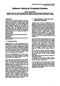
that our framework employ existing planning techniques, and does not propose a new one. An abstract workflow describes a set of tasks and the data dependencies among them without identifying the actual resources that will be used during the workflow execution. At the tactical phase, an abstract workflow is mapped into a concrete workflow which identifies the actual resources associated with the workflow tasks. It is important to note that at the strategic phase, the resources associated with the tasks are referred to by a logical name, which should be sufficient to identify the actual resources at the tactical phase. In this way, an abstract workflow can be mapped into different concrete workflows by using different combinations of resources. At the operational phase, the concrete workflow is executed. Figure 1 presents a simplified view of our approach for the dynamic generation of workflows.
Figure 1: Overview of workflow generation Our approach for workflow generation is based on the explicit representation of feedback loops [7], [15] between the three phases, previously identified. In case a fault occurs at a particular phase and that phase is not able to handle it, the processing resumes at the previous phase. In case of an error is detected during the execution of the concrete workflow, a recovery workflow is generated and executed before a new concrete workflow is generated at the tactical phase. If it is not possible to generate a new workflow (e.g., there are not enough resources), the generation goes back to the strategic phase, where a new abstract workflow is generated. In the eventuality of not being possible to generate an abstract workflow, the process for generating workflows finishes with an error. Our framework is based on three principles, which are detailed in the following: pre-defined task templates that are used for generating workflows, domains artefacts that are defined during the instantiation of the framework, and a reference process that defines the main activities2 of workflow generation. All these three principles are customised depending on the application domain.
2.1
Task Templates
The instantiation of the framework requires the definition of application specific task templates in terms of their pre- and post-conditions. The definition of a task template involves a model, a specification, and an implementation. A task template model is used to represent a task template within the framework, and is defined based on a task template metamodel [9]. A task template specification is described in terms of the Planning Domain Definition 2 In this work, activities refer to the steps of the generation, while tasks are associated with the generated workflow.
Language (PDDL) and contains the task’s pre- and postconditions. A task template implementation is defined based on the workflow execution environment. The implementation of these templates are structured in terms of atomic actions [11], as a means for incorporating fault tolerance, based on exception handling, into the workflow execution. Task templates can have two possible outcomes: Success, representing the successful execution of the task, and Failure, representing failure in the execution of the task. A task template implementation may incorporate a recovery path, which is activated when there is a failure during execution of the task, or a violation of its post-condition.
2.2
Generation Domain Model
The domain model captures all artefacts that must be defined when instantiating the framework. It includes a domain specific metamodel, a PDDL domain model, a set of transformation rules, and the task templates that can be used during the generation. The domain specific metamodel identifies the elements that can be used for defining domain specific models, and is used as basis for the definition of the PDDL domain model. The PDDL domain model contains the types available in the planning domain, and the predicates that can be used for expressing pre- and post-conditions of task templates. It also contains the possible task templates that can be used. Transformation rules are used for translating domain specific models into PDDL problem models. A PDDL problem model identifies the pre- and post-conditions to be considered by the planner, which together with the PDDL domain model, is used for generating a plan (captured by a PDDL plan model ). For supporting this, the framework defines a PDDL metamodel, that allows the representation of the different PDDL models. The framework also defines a task template metamodel that is used for the definition of task templates.
2.3
Generation Process
Each of the three phases of the framework is composed by several activities that have been organised in a “reference process”, which is responsible for coordinating the generation and execution of workflows. The reference process can be customised according to the domain in which the generated workflow is going to be applied. For generating abstract workflows, the strategic phase process starts by obtaining the current state of the resources of the system, and the goals associated with the workflow. These are then translated into pre- and post-conditions expressed in a PDDL problem model that is used by an AI planner. In case a plan has been found by AI planner, the plan is subsequently translated into an abstract workflow that is passed to the tactical phase. The generation of a concrete workflow at the tactical phase starts by identifying the resources associated with the abstract task parameters (called concrete parameters), which will define what resources are required for the tasks. The next step is to select the appropriate concrete tactical tasks, which define how the tasks of the abstract workflow are implemented. The process associated with the operational phase is responsible for controlling the execution of the generated concrete workflow. This phase is also responsible for generating
and executing a recovery workflow when abnormalities are encoutered during execution of the concrete workflow.
3.
DYNAMIC PLANS FOR INTEGRATION TESTING
Our approach for component-based integration testing is based on the instantiation of the framework for dynamic generation of workflows. In this instantiation, our main objective is the generation of a workflow for coordinating the integration testing of a software system. Thus, we assume that given the architectural configuration of the system, there are mechanisms responsible: to calculate the integration order of the received configuration, to provide any stubs that might be necessary, and to provide the test cases that will be used during testing. This section details our approach for integration testing, describing the artefacts that have been defined as part of the integration testing domain, the integration testing process defined for controlling the generation and execution of workflows, and the integration testing infrastructure developed for supporting the integration testing process.
3.1
The Integration Testing Domain
The artefacts defined for the domain of integration testing are: an architectural metamodel, its associated PDDL domain model, the set of transformation rules, and the task templates being considered.
3.1.1
Architectural Metamodel
The metamodel captures the concepts and properties associated with software components and their configuration. Following our division between abstract and concrete workflows, architectural models are also divided into two levels of abstraction. In this way, an abstract configuration describes a system structure in terms of its components, identified by a logical names, their types and connections, but abstracting away from the actual component instances. While, a concrete configuration describes a system configuration in terms of actual component instances, and their respective attributes [8]. The defined architectural metamodel is an extension to the xADL 2.0 architectural description language [10]. We have created an EMF3 description based on xADL 2.0, and then extended it allowing the representation of different properties associated with architectural elements. Our extension allows the representation of different non-functional properties that can be used during the selection of components (e.g., availability, correctness, cost and response time), and properties associated with the execution of tests on software components (e.g, if a component has been successfully tested, or if it has failed a test). We have also included elements for capturing the integration order of the components of a configuration.
3.1.2
PDDL Domain Model
The PDDL domain model for integration testing includes predicates to indicate whether or not a component has been integrated into a configuration, and whether a component has been tested. It also allows to capture the integration order of the involved components. Figure 2 presents the PDDL description of the domain model. 3
http://www.eclipse.org/emf
• ClearTest: responsible for clearing the tested property of components. • RestoreConfiguration: responsible for restoring the system to a particular configuration.
Figure 2: PDDL domain for component-based integration testing. The domain identification (IntegrationTestingDomain) is presented on line 1. The requirements keyword (line 2) identifies the PDDL features used in this domain, where adl identifies the rules used for defining actions, pre- and postconditions, while fluents allows the use of functions in the domain. The (integrated ?C - component) predicate (line 5) represents that a component has been successfully integrated into a configuration, while the (tested ?C - component) predicate (line 6) represents that a component has been tested. The functions (presented on lines 8 - 11) are used for incorporating the integration order of the components involved into the planner, where testing step and integration step are used to capture, respectively, the current testing and integration step at each stage of the plan, and integration order indicates the integration order of its associated component.
3.1.3
Transformation Rules
The transformation rules for integration testing are based on the architectural metamodel and the PDDL domain model, translating configuration models into pre- and post-conditions expressed in a PDDL problem model. Currently, we assume the system to be in a state of non-configuration, as a consequence the transformation rules have to consider the complete integration of the system. The transformation rules are based on the following steps:
ClearTest and Restore configuration are used in the recovery workflow that is generated when a failure occurs at the operational phase. IntegrateComponent and RestoreConfiguration involve changes in the system configuration, and they are associated to workflows automatically generated using the reconfiguration process presented in [8][9]. In the sequence, we present an example of task template specification and task template implementation for the operation for conducting tests on a particular component.
Figure 3: PDDL specification of the TestComponent task template. Figure 3 presents the task template specification for the TestComponent task template. The parameter of this task template is presented on line 2 (?C - component). The precondition states that the component has not been tested (line 4), and that it must be integrated (line 5). It also includes a predicate for considering the current testing step and the integration order associated with the component under test (line 6). The post-condition states that the component should be tested (line 9), and that the testing step is incremented by 1 (line 10).
1. Include the components of the selected configuration as not integrated and not tested in the workflow precondition. 2. Include the integration order in the workflow pre-condition, using the order of each component for populating the the testing step and integration step and integration order functions. 3. Include the components of the selected configuration as tested in the workflow post-condition.
3.1.4
Task Templates
As part of the instantiation of the framework, it is necessary to define the task templates that can be used for generating workflows. These task templates are based on the PDDL domain model and on the architectural metamodel. For integration testing, we have considered four task templates: • IntegrateComponent: responsible for integrating a component into a particular configuration. • TestComponent: responsible for conducting test in a component.
Figure 4: Task template for running tests in a component. Figure 4 presents the task template implementation for the TestComponent operation, and contains the following activities. The pre-condition checks if the component under test is ready to be tested (e.g., if it has been integrated in the current system configuration). The Run test(C) activity represents the execution of the test case(s) associated with component C. Tests are conducted based on call to operations of the component under test. The post-condition confirms the success of the test case(s) execution, and checks if the component has been marked as tested. This task template finishes successfully when the post-condition is evaluated to
true after the test execution. In case of a failure during test execution, or a violation of post-condition, the Recovery is activated, marking the component as failed and finishing the execution of the task template with a failure outcome. The reason for failing is saved in a log.
3.2
The Integration Testing Process
The integration testing process is an instantiation of the generation process provided by our framework (Section 2.3), and explores the different domain artefacts presented on Section 3.1. At the strategic phase, the process generates an abstract workflow based on an abstract configuration, the integration order calculated for this configuration, and any necessary stubs. At the tactical phase, a concrete workflow is generated based on a concrete configuration and the test cases that are going to be used with each concrete component. While at the operational phase, the concrete workflow is executed and, in case of failures during its execution, a recovery workflow is generated and executed before the process goes back to the tactical phase. Following the structuring of the different phases based on feedback control loops (Figure 1), the integration testing process deals with failures in the following way: in case it is not possible to establish a particular concrete configuration (a concrete component has failed the test), the process selects a new concrete configuration for the system (i.e., trying to replace the failed component), and generates a new concrete workflow by selecting a new set of test cases. In case it is not possible to generate a new concrete workflow (e.g., there is not enough concrete components for establishing the selected abstract configuration), the process goes back to the strategic phase where a new abstract workflow is generated. The process finishes with a failure in case it is not possible to generate another abstract workflow. In the sequence, we detail the activities of the different phases of the integration testing process.
3.2.1
Strategic Phase
The main objective at this phase is to find the sequence of tasks that will compose an abstract workflow. Figure 5 presents an overview of the activities of the strategic phase. The activity Obtain current configuration obtains the initial architectural configuration of the system. The Obtain abstract configuration activity obtains the abstract architectural configuration that should be tested. If no abstract configuration is available, the process finishes with a failure outcome. The Calculate integration order activity represents the identification of the integration order associated with the selected abstract configuration, and is also responsible for identifying and including the stubs necessary for the integration testing into the architectural model. The outcome of this activity is an abstract architectural model with its associated integration order and necessary stubs. The Translate into pre/post activity uses the transformation rules presented in Section 3.1 for translating the architectural models (current configuration and abstract configuration) into a PDDL problem model with the pre- and post-conditions that will be used for generating a workflow. The Run planner activity is responsible for executing an AI planner using the PDDL problem model, the PDDL domain model, and task templates. The outcome of this activity is PDDL plan. In case it is not possible to find a plan for the
Figure 5: Overview of the strategic phase of the integration testing process. given inputs (e.g., lack of stubs) the process goes back to the Obtain abstract configuration activity. Finally, the generated PDDL plan is translated into an abstract workflow by the Translate into workflow activity. A detailed view of this activity is presented in Figure 6 using an activity diagram notation. This activity parses the PDDL plan, and instantiates each of its tasks with their corresponding task template implementations, resulting in an abstract workflow. This activity is also responsible for instantiating the pre- and post-conditions of the generated workflow. Pre-condition instantiation is part of the initialisation of the abstract workflow. The instantiation of each task involves the processing of its implementation (e.g., loading the implementation and setting the inputs), and its association to the abstract workflow (Save abstract sub-workflow). The decision point in the diagram captures the task templates presented on Section 3.14 , while the loop is used to iterate through all tasks of a plan. A PDDL plan contains several instantiations of the IntegrateComponent task template depending on the number of steps in the integration order, thus the need to dynamically generate abstract sub-workflows responsible for changing the system architecture; one sub-workflow for each IntegrateComponent task of the PDDL plan. This is achieved by exploring the reconfiguration process presented in [8][9], which produces a workflow for changing a system configuration based on models representing the current and the target configurations. In this way, the instantiation of each IntegrateComponent task (represented by the Instantiate IntegrateComponent task of Figure 6) of a PDDL plan involves: 1. Process task implementation: The instantiation (loading and population of the task inputs) of a task template implementation. 2. Build target model: The definition of configuration models representing the state of the system before (current) and after (target) the corresponding IntegrateComponent task. 3. Reconfiguration strategic phase: The activation of the reconfiguration process using the defined configuration models (current and target) as input [8][9]. 4. Save abstract sub-workflow: The association of the generated abstract reconfiguration workflow with the IntegrateComponent task implementation. The definition of the configuration models used as input for the reconfiguration process depends on the integration order of the associated IntegrateComponent task. The current configuration of the first IntegrateComponent task of 4 Due to space constraints, we do not detail all task templates.
Figure 6: Detailed view of the Translate into workflow activity. the generated plan, corresponds to an empty configuration model. While in the other integration steps, the target configuration model of the previous IntegrateComponent task is used as current configuration model of the next IntegrateComponent task. e.g., the target configuration of the first task is used as the current configuration of the second task. The target configuration of a IntegrateComponent task is defined based on its current configuration. This is achieved by including the component associated with the IntegrateComponent task in the configuration, together with all connections in which this component is the client, and their respective required components in case they have been tested. In case a required component has not been tested, it is replaced by a stub. In case the component being integrated has been previously replaced by a stub, the stub is removed from the target configuration model, and the component is used in all connections in which the stub was involved. At the end of the strategic phase, the abstract workflow and its respective abstract configuration model are passed to the tactical phase. In case of a problem at the tactical phase, the process starts again from the Obtain abstract configuration activity.
3.2.2
component. These test cases are also used for configuring any necessary stubs, based on the strategy adopted by Rocha and Martins [18]. We assume that test cases are available, and associated to each concrete component in the form of meta-data. Finally, the Replace tasks activity replaces the abstract tasks of the abstract workflow with the concrete tasks (identifying the concrete components and associated test cases), resulting in a concrete workflow. In case of a problem at the operational phase, the process tries to select a new concrete configuration (Select concrete configuration activity) before generating a new concrete workflow, reusing the abstract workflow and the abstract configuration previously defined. In this case, the selection of a new concrete configuration tries to replace the component that failed the test. In case it is not possible to find a concrete configuration, the process goes back to the strategic phase.
3.2.3
Operational Phase
This phase of the integration testing process is responsible for executing the generated concrete workflow. An overview of the activities of this phase is presented in Figure 8.
Tactical Phase
At the tactical phase, the abstract workflow is converted into a concrete workflow by associating the correspondent concrete components, and the test cases of the component under test. An overview of the activities of this phase is presented in Figure 7.
Figure 8: Overview of the operational phase of the integration testing process. Figure 7: Overview of the tactical phase of the integration testing process. The Extract abstract tasks activity extracts the abstract tasks that compose the received abstract workflow. The activity Select concrete configuration finds a concrete configuration for the system, based on the abstract configuration identified at the strategical phase [8][9]. Once the concrete configuration has been identified, the Replace tasks parameters activity uses the concrete components to replace the logical parameters of the abstract tasks. The Select test cases activity identifies the test cases to be used for each concrete
The first activity of the generated workflow (Check precondition) checks whether the components are ready to be tested, i.e., quiescent state. Once the workflow pre-condition is satisfied, the tasks of the generated concrete workflow are executed (represented by Workflow tasks activity) by integrating and testing the components and stubs. The Check post-condition activity checks whether all the involved components are marked as tested. In case of a problem in any of these activities, the Recovery is activated. In case of problems during execution of the generated workflow, or a violation in its post-condition, the recovery undoes the effects of the generated workflow before
returning control to the tactical phase. This is achieved by the Generate recovery workflow and Execute recovery workflow activities. For now, we are assuming the use of backward error recovery as the means for handling errors. In this way, a recovery workflow is generated based on a simple undo scheme. The recovery workflow includes tasks that clear the tested flag of each component that has been successfully tested, and attempts to restore the system architecture to the configuration it had at the beginning of the integration testing process through the RestoreConfiguration task.
case of failures during execution of the generated workflow. The Registry component is responsible for providing updated information about the Resources. The Test case selector selects the test cases associated with the component under test (Select test cases activity). We assume that all available test cases have been previously defined, and are stored in the Test case repository component. The tests are executed through calls to the provided interfaces of the components, and we have used the JUnit5 framework as execution infrastructure.
3.3
4.
The Integration Testing Infrastructure
In the sequence, we present the infrastructure developed for supporting our approach, which is shown in Figure 9. Most of the components in this infrastructure are provided by our framework, though some needed to be changed (Customisable element - e.g. Model translator), and few needed to be introduced (Domain specific element - e.g. Ordering calculator). The integration testing process is managed through workflows modelled using the Yawl workflow modelling language [19], and are executed in the Yawl Workflow Management System (WfMS).
EVALUATION
In order to evaluate our approach, we have applied our prototype to a case study. In this section we present the case study, describe some of the experiments performed, and draw some conclusions on the experience gained.
4.1
Case Study
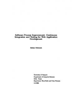
The case study used is a simple web shop application, which can be employed to sell goods on the Internet. The software architecture of this application involves five component types: FrontEnd, ShopServ, ProdDB, PriceCalc, and DeliveryQuot. The FrontEnd represents an user interface for purchasing products. The ShopServ is the coordinator of the application, controlling the enquiries and purchases of the clients. The ProdDB represents the products stock database. The PriceCalc captures the business logic responsible for calculating the total price of a client’s shopping basket, considering the delivery costs (calculated by the DeliveryQuot component). Gui1 :C1 :FrontEnd
Gui1_IR
SS1 :C2 :ShopServ
SS1_IP
SS1_IR1
PDB1 :C3 :ProdDB
PDB1_IP SS1_IR2 PCNP1_IP
Figure 9: Overview of the infrastructure for supporting the generation of workflows. The Model translator component supports the Translate into pre/post activity, and is customised with the transformation rules presented in Section 3.1, which are defined based on the Atlas Transformation Language (ATL) [14]. The Planner component (supporting the Run planner activity) is the Sgplan planner [13], which considers the PDDL domain model and task templates presented in Section 3.1. The Workflow translator component supports the Translate into workflow activity, and is customised for dealing with models based on the metamodel presented in Section 3.1. The Reconfiguration generator component (Reconfiguration strategic phase activity) represents the infrastructure for generating reconfiguration workflows [8] [9]. The Recovery handler component implements the recovery mechanism of the operational phase. The Client interface component initiates the integration testing process, and is implemented as simplified graphical interface. The Ordering calculator supports the Calculate integration order activity. Stubs are treated as software components and are managed by the Configurator component, which is also responsible for the Obtain abstract configuration and Select concrete configuration activities. The selection of a concrete configuration considers a simple utility function based on the linear combination of the utilities of the different components. The Configurator is also responsible for finding replacements for concrete components in
PCNP1 :C4 :PriceCalcNP
PCNP1_IR DQ1_IP
DQ1 :C5 :DeliveryQuot
Figure 10: Example of concrete configuration with references to abstract components. Figure 10 presents an example of a concrete configuration of the web shop application. Following the division between abstract and concrete configurations, each component instance of a concrete configuration is associated to a logical name (of an abstract configuration) and type. The following convention will be followed in the name of components: Gui1 :C1 :FrontEnd indicates that the component instance Gui1 is associated to the logical name C1 and has type FrontEnd.
4.2
Experimental Results
The experiments performed consider the configuration of Figure 10. According to the integration testing process presented in Section 3.2, once the integration order is calculated, the Translate into Pre/Post activity is activated, resulting in a PDDL problem model. A snippet of problem model described in PDDL is presented in Figure 11. The objects entry identifies all components involved in the problem. In case there are stubs involved, these are treated like other components. The pre-condition (init on line 8) states the initial integration step and testing step (line 9), and the integration order of the participant components (lines 10 5
http://www.junit.org/
12). It also states that all involved components are not integrated and not tested, which is indicated by the absence of the associated predicates (integrated and tested). The postcondition (goal on line 14) states that all components must be tested (lines 15 - 17).
corresponding test cases to the TestComponent tasks. Finally, the generated concrete workflow is executed, integrating and testing the system configuration, one component at a time. This experiment has been repeated involving different abstract/concrete configurations, and considering components that failed their associated test cases. In all experiments, our approach has been able to generate a workflow for managing the integration testing even when considering failures in the process.
4.3
Figure 11: Example of pre- and post-conditions in PDDL. This problem description is used as input for the Run planner activity, which generates a PDDL plan. Figure 12 presents an example of a plan generated during this experiment, where we can notice that tasks for integrating and testing components are intercalated.
Figure 12: Example of generated plan in PDDL. The PDDL plan is then translated into an abstract workflow by the Translate into workflow activity. Figure 13 presents an abstract workflow generated during this experiment, where we can notice tasks for integrating (IntegrateComponent) and testing (TestComponent) components. Each IntegrateComponent task is associated with a sub-workflow that changes the system configuration for including the component being integrated. Figure 14 presents the abstract workflow generated for the (IntegrateComponent C5) task. The generated abstract workflow is then converted into a concrete workflow by replacing the logical names with the concrete components of Figure 10, and by associating the
Figure 14: Sub-workflow associated with the IntegrateComponent C5) task.
Quantitative Results
We also conducted experiments for evaluating the performance of our approach considering the configuration of Figure 10. The numbers presented corresponds to the average of five executions. The first analysis performed was related to the activities of the integration testing process, where from a total generation time of 1513.23 ms, only 17.92 ms were associated with the tactical phase of the generation. Focusing on the strategic phase, we have measured the times of the activities of the process shown in Figure 6, which are shown in Table 1. This data has confirmed that Instantiate tasks is the most time consuming one since it needs to generate a workflow for each IntegrateComponent task. The impact of these generations is demonstrated in Table 2, which shows the times for instantiating each task of the plan of Figure 12. It was observed that the total time associated with the generation of reconfiguration workflows (1455.74 ms) correspond to 99.82% of the time associated with the Translate into workflow activity (1458.60 ms). Parse PDDL plan 0.190 ±0.044
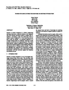
Table 2: Times for instantiating the tasks of a PDDL plan (in ms). We have repeated this analysis for the other configuration sizes, and besides the constant 99% of impact, the standard deviation of generating reconfiguration workflows decreases with bigger configuration sizes. It was also observed that the time for generating a reconfiguration workflow at each integration step increases with the number of steps, which is caused by the increase in the number of components involved in each integration step. All components of the “current” and “target” system configurations of a particular integration step are considered by the AI planner when generating a reconfiguration workflow. Even though the generated reconfiguration workflow may not involve all components, these components are treated as planning objects by the AI planner, which increases the search space,
Figure 13: Example of abstract workflow for the configuration of Figure 10.
Figure 15: Time for generating a workflow varying the size of the configuration. which explains the increase in the generation time with the number of steps. We have also conducted another set of experiments for evaluating the scalability of our approach. This experiment involved a software architecture based on the pipe-and-filter architectural style, considering three types of components: source, filter and sink; where a different number of filters can be between a source and a sink. In this way, we can control the configuration size (in terms of number of components/connections) by changing the number of filters inFigure 15 presents the times for generating a workflow volved. when varying the number of components in the configuration. In our approach, the time it takes to generate a workflow appears to be linear regarding the number of components in the configuration, for a reasonable amount of components. These initial experiments have demonstrated the feasibility of our approach, demonstrating that the architectural reconfigurations involved in the integration testing cause most impact in the generation of workflows. The experiments also presented very promising results about the scalability of the approach when considering different configuration sizes for a particular architectural style up to a reasonable number of components.
5.
RELATED WORK
This section presents a brief literature review in the area of component-based integration testing in order to position our work, and to identify those contributions that are complementary to our approach.
The Component Deployment Testing (CDT) is a framework for the development and codification of tests, providing an environment for executing tests over a selected candidate component [4]. This work is similar to ours since the CDT framework explores the decoupling between test specifications and test execution based on the use of architectural models at different levels of abstraction. Different from the CDT framework, our work considers not only the execution of tests, but also the modifications of the system configuration (e.g., connection and disconnection of components/stubs) based on the integration order of the components of the system under test. The CDT framework has been defined as a development-time tool, requiring manual effort for integrating the different components, for example, while our approach focuses on providing automated testing capabilities during run-time. Another related work is the approach for conducting compatibility test of component-based software systems exploring configuration models at different levels of abstraction [20] [21]. That approach has focused on testing whether a system can be built across all of its possible configurations when considering different versions of the involved components. Different from our approach, whose objective is to obtain a single configuration that passes the integration test during run-time, and not testing all possible combinations. Another difference is that our approach performs functional tests between components considering their required and provided interfaces, which is indicated as future work in their approach. Moreover, in their work, the testing order of the components is manually defined, with no support for configurations that require component stubs. In our approach, we have assumed the existence of the different artefacts involved in the integration testing process, for example, the test integration order, stubs and test cases. However, in order to provide a fully automated environment for conducting integration tests, the approach should have the capability of generating these artefacts automatically during run-time. Moreover, it should be able to select different test cases according to the component under test and the criteria and coverage being considered [2]. Regarding this, in the following we present other approaches, complementary to ours, that should enable the development of an automated integration testing approach. The approach presented by Hewett and Kijsanayothin [12] could be applied as the means for calculating the compo-
nents integration order. Another problem is associated with the generation of stubs for component-based testing, and there are already several approaches that could be employed [3] [18]. Besides defining the integration order and the necessary stubs, it is also necessary to define the test cases that will be used during the tests. For now, our approach has assumed that the test cases have already been defined and are provided for each component instance as meta-data, which is similar to the idea of built-in-testing [5]. However, amongst the existing contributions, we can identify two that could be used with our approach [1] [6].
6.
CONCLUSIONS
This paper has presented an approach for the dynamic generation of plans that coordinate the integration testing of component-based software systems. The approach presented in this paper is an instantiation of a more general framework for the dynamic generation of processes that has been previously instantiated for managing software reconfiguration [8] [9]. The experiments performed demonstrated that our approach is able to generate workflows for managing integration testing, that the most time consuming activity when generating a workflow is related to the architectural reconfiguration of the system being tested, and that the time to generate a workflow appears to be linear in relation to the number of components in the configuration. Although our approach has produced quite promising results, we have identified some limitations. Our approach assumes that a component that has been tested while connected to a stub does not need to be re-tested when the stub is replaced by original component. The approach is also restricted to the generation of sequential workflows, and the scalability experiments considered only a particular type of architecture (based on the pipe-and-filter style) and a reasonable number of components. As future work, in addition of tackling the above mentioned limitations, we intent to fully develop an approach in which the testing artefacts are dynamically generated by exploring some of the approaches mentioned in Section 5. We also intent to explore workflow verification and validation techniques in order to guarantee the correctness of the generated workflow based on the received configuration; and to explore ideas from computational reflection, including a “meta generation” level into our framework, which would allow tuning some aspects of the dynamic generation of plans, for example, by changing the type of stub being generated based on the coverage criteria being considered.
7.
ACKNOWLEDGMENTS
Carlos Eduardo da Silva is supported by the Programme Alβan, the European Union Programme of High Level Scholarships for Latin America, scholarship no. (E07D401107BR). Rog´erio de Lemos is co-financed by the Foundation for Science and Technology via project CMU-PT/ELE/0030/2009 and by FEDER via the Programa Operacional Factores de Competitividade of QREN with COMPETE reference: FCOMP-01-0124-FEDER-012983.
8.
REFERENCES
[1] D. L. Barbosa et al. Automating functional testing of components from UML specifications. IJSEKE, 17(3):339–358, 2007.
[2] A. Bertolino. Software testing research: Achievements, challenges, dreams. In ICSE FOSE’07, 2007. [3] A. Bertolino et al. Model-based generation of testbeds for web services. In TestCom/FATES’08, volume 5047 of LNCS, pages 266–282, 2008. [4] A. Bertolino and A. Polini. A framework for component deployment testing. In ICSE’03, pages 221–231, 2003. [5] D. Brenner et al. Reducing verification effort in component-based software engineering through built-in testing. Inform Syst Front, 9(2-3):151–162, 2007. [6] L. C. Briand et al. Automated, contract-based user testing of commercial-off-the-shelf componens. In ICSE’06, pages 92–101, 2006. [7] Y. Brun et al. Engineering self-adaptive systems through feedback loops. In Software Engineering for Self-Adaptive Systems, volume 5525 of LNCS, pages 48–70. 2009. [8] C. E. da Silva and R. de Lemos. Using dynamic workflows for coordinating self-adaptation of software systems. In ICSE SEAMS’09, pages 86–95, 2009. [9] C. E. da Silva and R. de Lemos. A framework for automatic generation of processes for self-adaptive software systems. Special issue on Autonomic and Self-Adaptive Systems at Informatica, To appear:13pp, 2011. [10] E. M. Dashofy et al. A comprehensive approach for the development of modular software architecture description languages. ACM Trans. Softw. Eng. Methodol., 14(2):199–245, 2005. [11] R. de Lemos. Architectural reconfiguration using coordinated atomic actions. In ICSE SEAMS’06, pages 44–50, 2006. [12] R. Hewett and P. Kijsanayothin. Automated test order generation for software component integration testing. In ASE’09, pages 211–220, 2009. [13] C. W. Hsu et al. Handling sof constraints and preferences in sgplan. In ICAPS Workshop on Preferences and Soft Constraints in Planning, 2006. [14] F. Jouault et al. ATL: A model transformation tool. SCP, 72(1-2):31–39, 2008. [15] J. Kramer and J. Magee. Self-managed systems: an architectural challenge. In ICSE FOSE’07, pages 259–268, 2007. [16] P. D. L. Machado et al. Component-based integration testing from uml interaction diagrams. In ICSMC’07, pages 2679–2686, 2007. [17] D. Nau. Current trends in automated planning. AI Magazine, 28(4):43–58, 2007. [18] C. R. Rocha and E. Martins. A method for model based test harness generation for component testing. J. Braz. Comp. Soc, 14:7–23, 2008. [19] W. M. P. van der Aalst and A. H. M. ter Hofstede. Yawl: Yet another workflow language. Inf. Syst., 30(4):245–275, 2005. [20] I.-C. Yoon et al. Direct-dependency-based software compatibility testing. In ASE’07, pages 409–412, 2007. [21] I.-C. Yoon et al. Prioritizing component compatibility tests via user preferences. In ICSM’09, pages 29–38, 2009.