Proceedings of ICAPP ’06 Reno, NV USA, June 4-8, 2006 Paper 6159
Dynamic System Model of LS-VHTR to Estimate Design Parameter Impacts on Safety Margin and Reactor Economics
A. L. Qualls and T. L. Wilson Jr. Oak Ridge National Laboratory P.O. Box 2008 Oak Ridge, TN 37831-6074 Tel: 865-574-0259, Fax: 865-574-0382 , Email:
[email protected]
Abstract—Early reactor analysis work for the U.S. Department of Energy’s (DOE’s) Liquid Salt– Very High Temperature Reactor (LS-VHTR) concept has focused primarily on detailed analyses of the core. This paper discusses ongoing analyses of the balance of plant and how it impacts overall system design. A dynamic system model of the end-to-end LS-VHTR has been developed to investigate the impact of major design parameters on systems performance, safety margin, and plant economics. The core model uses simplified thermal-hydraulic analyses to calculate four characteristic radial coolant channel parameters during transients. The core model is coupled to a multireheat Brayton power conversion system model through an intermediate salt-coolant loop model. A passive, safety-related heat-removal system is modeled for reactor pressure vessel protection. Critical parameters, such as peak fuel and vessel temperatures and peak temperatures and pressures in the power conversion loop, are estimated during proposed transients. The impacts of design parameters on component design requirements, safety margin, and economics are to be investigated. Transients initially analyzed will include loss-of-coolant-flow accidents. For initial transients, the axial- and radial-power profiles within the core will remain constant, with power levels decreasing in proportion to the time-dependent decay heating rate of the fuel. Later transients will represent spatial core power shifts during transients without scram. Results from simplified economic models will support relative comparisons among system design options.
I. INTRODUCTION The design of the Liquid Salt–Very High Temperature Reactor (LS–VHTR) is evolving. A dynamic simulation model is being developed to provide a flexible platform for investigating the various design concepts. The model will be used to study the behavior of the integrated plant to perturbations and larger transients, including component failures, loss of force flow, loss of offsite power, etc. Preliminary results from the initial version of the dynamic model, which still includes some significant simplifications, have been coupled with a simplified cost model to demonstrate the relationship among plant performance, safety margin, and economics.
larger core with less power density may produce lower vessel temperatures during a loss of forced flow accident; however capitalization, and operating costs may increase. By linking the proper design data to both an economic model and an operational model of the LS-AHTR system, the design changes that influence safety margin can be judged relative to the resulting economic consequences. The linked analysis allows the economic and safety implications of design options to be studied in unison to better understand of how advanced, high-temperature power systems may operate within the constraints of the existing competitive power market. II. RELEVANT LS–VHTR FEATURES
The inherent safety of the system must be discussed in relation to the relative economics of the system. If an advanced reactor system cannot be made to compete both economically and in terms of operational safety then it will not be utilized. Increased safety margin generally comes at the expense of economic attractiveness. For example, a
The LS–VHTR concept is proposed to operate at higher temperature to increase power conversion efficiency or, alternatively, to produce hydrogen. The ability to produce electricity at efficiencies exceeding 50% is approaching viability because Brayton power conversion
Proceedings of ICAPP ’06 Reno, NV USA, June 4-8, 2006 Paper 6159
technology is maturing to the point where the necessary power levels can be generated at the temperatures of interest. High temperature liquid cooled reactor concepts have potential economic advantages over gas-cooled hightemperature concepts because the liquid coolant permits operation of larger cores at higher power densities while maintaining similar levels of operating safety margin. II.A. Reactor Core The LS–VHTR concept is in the early stages of development. A proposed baseline LS–VHTR system1 will produce approximately 1250 MW(e) from an overall core output of approximately 2400 MW(t). The baseline core is an assembly of hexagonal, prismatic, graphite fuel blocks. Each block is 36 cm across the hexagonal flats and 79.5 cm tall. The ~10-m long by ~8-m diameter core and reflector is composed of 324 fueled block assemblies surrounded by unfueled graphite reflector blocks contained within a 9.2-m diameter vessel. The Thermal Blanket System (TBS) is a key design feature that distinguishes the LS–VHTR from pool type sodium-cooled reactors. The TBS allows the LS–VHTR to take advantage of very high operating temperatures of the molten salts while the vessel remains at lower temperature. Variants of core design can utilize different arrangements of a single fuel compact design, arrangements using compacts with different enrichments and more complex fuel management schemes; or the core could be a different design altogether (i.e., pebble bed). The operating power outputs of the larger advanced reactor designs are ultimately limited by the ability to maintain appropriate safety margin during postulated transients. The baseline LS-VHTR design uses a passive, air-cooled heat removal system similar to the reactor vessel auxiliary cooling system developed for the S-PRISM reactor to keep the reactor vessel temperature within acceptable levels during transients. In this design, heat is transferred through the TBS (mostly by conduction) to the reactor vessel wall. Heat is transferred through the wall by conduction and from the wall by radiation across an argonfilled annular gap to a surrounding guard vessel. Heat is ultimately removed from the guard vessel by natural circulation to ambient air and by radiation to the ground. II.B. Power Conversion System (PCS) A preferred layout for the LS–VHTR PCS has not been proposed; therefore we are at liberty to design one that fits within the constraints of the program. The multistage molten–coolant gas cycle (MCGC) is used as a reference design for the PCS. The Brayton power systems are significantly smaller than equivalent steam cycle systems that must include large subatmospheric turbines
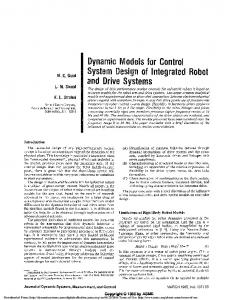
and moisture separators, and they allow operation at higher temperatures. The Brayton system is currently modeled as with three turbines powering three compressors and a single synchronous generator feeding the regional grid. The grid will accept power from the generators or will provide power to the power train depending on the total power balance between the turbines and the compressors. Therefore two types of transients can occur: one in which the rotational frequency of the power train remains fixed or one in which grid synchronization is lost and the power train rotational frequency deviates from the design value. For this work, the electrical grid is modeled as sufficiently large to preclude LS–VHTR operation from impacting grid frequency. II.C. Flow Loops A schematic of the LS–VHTR flow loops is shown in Figure 1. The LS–VHTR is proposed for both power generation and hydrogen production. The reactor system modeled within the context of this paper is coupled to the multi-reheat Brayton system layout. In the baseline LS– VHTR design, molten-salt coolant flows down through the reactor core and up through a pair of central return pipes with bypass flow, siphon breaks, and centrifugal pumps. The siphon breaks introduce bypass coolant flow, which is an efficiency loss; however, they play a significant role in limiting the response of the system during certain loss of forced flow accidents. The energy from the primary loop salts is transferred to an intermediate salt loop through a salt-to-salt intermediate heat exchanger (IHX). Energy is transferred to the PCS working fluid through a series of parallel salt-to-gas heat exchangers, and waste heat is removed from the working fluid through a series of gas-towater heat exchangers. The PCS turbines and compressors operate at successively reduced pressures resulting in high-pressure, medium-pressure, and low-pressure units. The helium inlet temperature into the turbines is dictated by the temperature, the design of the heat exchangers, and flow rate of the intermediate coolant. The helium is reheated to its peak temperature before being passed through successive turbines, but it passes through them at reduced pressure; therefore, each turbine is of a different design. In the Brayton system, a significant portion of the power generated from the turbines is required to compress the working fluid as it passes through the cycle. The percentage of power can be reduced if the working fluid is cooled prior to the compression stages, because less work is required to compress colder gas. The gas temperature increases during compression, and to compensate the fluid is compressed in stages with cooling between stages. Brayton cycles are most efficient when the power required
2
Proceedings of ICAPP ’06 Reno, NV USA, June 4-8, 2006 Paper 6159
for multistage compression is shared evenly over the stages. Because they too operate at different pressures, the compressors are all of unique design as well. The turbines, compressors, and generators can operate on a common shaft, or each of the units can operate as entirely independent components capable of operating at different rotational frequencies. The initial PCS was developed assuming that all three turbine and compressor stages operate on a common shaft. The advantages of decoupling the turbines from the compressors include the ability to independently optimize them; however operating them on a common shaft reduces the number of control and safety features that must be incorporated to prevent overspeed of components.
recuperator removes unused heat from the exhaust of the final turbine and returns it to the working fluid after the final compression stage; just before it enters the first of three salt-to-gas heat exchangers. Flow of the secondary salt is out of the secondary side of the IHX and into the three salt-to-gas heat exchangers in parallel. The salt out of these heat exchangers is collected into a common manifold and returned to the secondary system pumps before returning to the IHX. The flow of helium through the three salt-to-gas heat exchangers is serial. The gas passes through one heat exchanger before passing through one of the turbines. The working fluid therefore passes through each turbine at (essentially) the same temperature but at successively reduced pressure.
A recuperator is necessary to increase the operating efficiency of the Brayton cycle to satisfactory levels. The
Fig. 1. Schematic representing three stage multiheat Brayton power generation system modeled for this study of LS–VHTR.
3
Proceedings of ICAPP ’06 Reno, NV USA, June 4-8, 2006 Paper 6159
III. MODEL DEVELOPMENT The LS–VHTR dynamic system model is developed in the Matlab-Simulink environment. The major components modeled are heat exchangers, turbines, and compressors. The reactor core is modeled as a heat exchanger with internal heat generation coming from nodes representing the fuel, a surrounding helium gap, and graphite. The remainder of the system is composed of (1) the reactor primary coolant system, (2) the IHX, (3) PCS heat exchangers (heat input and rejection), and (4) turbines and compressors. Environmental conditions and measurement and control strategies are modeled as supplemental components to the major system components. Alternative passive safety systems are under consideration2 and these systems can also be modeled as distinct supplemental components for inclusion in the larger model. Components are modeled individually and interconnected by standardized inputs and outputs. Systems are modeled by linking components together. Some components are initially represented with lowfidelity models incorporating analytical approximations and empirical relationships. Higher fidelity modules, including off-line FORTRAN or C modules, can be added as needed due to the modular system architecture. The model estimates heat and mass flows between each component within the primary, secondary, power conversion, and waste heat removal loops; the loops transfer heat between each other across common boundaries. Plenums are modeled between components where mixing of fluids at different thermodynamic conditions can occur. The majority of the flow in the primary loop is modeled from the core outlet plenum, through the primary heat exchanger, through a single primary pump, and into a core inlet plenum. A controllable amount of bypass flow can be diverted around the IHX directly into the core return leg. The flows and pressure drop relations around the primary and secondary loops are modeled by deriving or assuming individual pressure drop coefficients for each major component in the loop. Pressure changes in the PCS loop are assumed to come only from the turbines and compressors at this time. Later versions will account for pressure drops through the heat exchangers. The reactor core thermal-hydraulics are modeled as four independent one-dimensional flow paths through the core; central, middle, and outer fueled regions in additional to an unfueled blanket region. The number of flow channels in each category of flow channel is somewhat arbitrarily chosen. Each of the vertical flow channels is modeled as six axial nodes. The power profile within the core can therefore be modeled with a four-point radial
profile and a six-point axial profile. The power generated within each of the 24 core nodes can be programmed independently, or they can be linked together to change power levels without changing radial or axial power profiles. A single set of point kinetics equations can be used to produce core power changes utilizing the constant profile feature. Individual transients may be programmed for each node to simulate responses calculated from higher fidelity core models or to represent decay heat after shutdown. The TBS is modeled as a conduction region between the unfueled blanket region and the reactor vessel inner wall. Argon is assumed to fill the annular region between the reactor vessel outer surface and the guard vessel inner surface; however, radiation heat transfer is the only heat transfer considered between the reactor vessel and the guard vessel. Heat is removed from the guard vessel outer surface by natural circulation to the atmosphere and by radiation to the ground. In the model simplified correlations for turbulent, unrestricted air flow are used to estimate natural circulation losses. The loss to the air and ground are set to total ~6 MW during normal full-power operation to be consistent with the more detailed RELAP analysis. Each heat exchanger model within the program is essentially the same modular, 12-node heat exchanger model. Inputs into the heat exchanger module include heat transfer coefficients (which must be calculated outside of the heat exchanger module), flow rates, specific heat and density of the fluids, channel number and dimensions, and specific heat, thermal conductivity, thickness and mass of the heat exchanger structural material. Accurate modeling of the heat flow and the coolant flow through the core is complicated and is best modeled with more powerful, computational fluid dynamic (CFD) tools. The models utilized in the dynamic system model cannot approach the fidelity of the CFD models. The dynamic system models are designed to capture the essence of the more sophisticated models at benchmarked operating conditions and mimic their results over limited operating ranges while operating in a reasonable period of time when tied to the model of the balance of the plant. Presently the model cannot adequately model flow reversal. For transients involving flow decreases from a pumped condition to one driven by natural circulation, the model is implicitly modeling an upward flow through the core. A heat exchanger model is under development that will allow flow reversal to be modeled.
4
Proceedings of ICAPP ’06 Reno, NV USA, June 4-8, 2006 Paper 6159
IV. BASELINE DESIGN AND MODELING Design of an integrated power system typically progresses from the desired power output and any temperature and pressure limits imposed. The choice of primary salt and the desired temperature increase across the core determine the flow rate of the primary system. This translates into the flow rate through the secondary system once that salt has been selected and the temperature drop across the secondary system determined. Working fluid temperatures are dictated by the maximum secondary salt temperatures (minus the temperature drop through the heat exchanger) and the heat rejection temperature (plus the temperature drop across the coolers). The heat rejection temperature for the system will be inherently limited to temperatures above ambient temperatures. Thus the working fluid temperature range is limited by the maximum temperature of the secondary salt and ~300 K. This temperature range sets the Carnot efficiency of the system, which represents the maximum possible PCS conversion efficiency. Other system irreversibilities and inefficiencies are taken with the Carnot efficiency to dictate the overall conversion efficiency of the system. Given that other losses are essentially constant, in order to maximize overall efficiency, the working fluid upper temperature must be increased to the highest possible value.
For this initial study 2LiF-BeF2 (FLiBe) has been chosen as the primary coolant. The secondary salt selected for this study is also 2LiF-BeF2 although a very different salt will most likely be used. Based on these selections, along with the other system configurations discussed above, the relevant values associated with the LS-VHTR and the proposed multireheat helium PCS have been derived or assumed and are listed in Tables I and II. TABLE I Heat Exchangers in System Heat exchanger (#) Primary to Secondary (1) Secondary to PCS (3) Recuperator (1) PCS to Waste (3)
Salt/Salt Salt/Helium Helium/Helium Helium/Water
Rating MW(t) 2400 800 1320 375
TABLE II Baseline PCS Characteristics Parameter Pressure Ratio Compressor Efficiency Turbine Efficiency Thermal Power Compressor Inlet Temperature Compressor Outlet Temperature Recuperatored Heat Helium Flow Rate Generator Efficiency
IV.A. Fluid Selection Salt selection is a function of many factors including neutronics, thermal-hydraulics, chemical interactions, and toxicity, among others. The dynamic system model is concerned primarily with the salt thermal-hydraulic properties and feedback coefficients related to reactor power (voiding coefficient of reactivity for example). For transients that do not involve a loss of primary coolant from the core, the parameters of interest are those related to the pumping and heat transfer characteristics of the salts. Important considerations in selecting salts are their melting and boiling points. The boiling point of the primary coolant determines the inherent margin to safety between normal operating temperatures and temperatures during postulated accidents. The freezing point of the primary system salt (which is typically higher than that of the secondary system salt) determines the minimum system temperatures that must be maintained during an outage to prevent freezing. The freezing point represents the temperature above which the salt must be maintained during maintenance by an auxiliary energy source. Maintaining the elevated temperature is a cost in terms of both equipment and energy. Increased melting point temperatures are also likely to result in the increased difficulty associated with maintenance operations.
Fluid type
Value 1.93 88% 93% 2400 MW(t) 308 K 359 K 1320 MW(t) 596 kg/s 98%
The core outlet temperature was limited to ~1123 K during normal operation at 100% power for this initial model of the system. The model predicts that for a core power of ~2400 MW(t), the expected gross electrical power output is ~1240 MW(e). The resulting expected overall system efficiency is approximately 53%. In this system an estimated 1317 MW(t) is transferred across the recuperator, ~750 MW is extracted from each of the three turbines, and ~330 MW is absorbed by each of the compressors. V. EXAMPLE CALCULATION V.A. Transient Calculation One of the safety parameters selected as the initial focus of investigation with the dynamic system model is the reactor vessel temperature. The investment in the
5
Proceedings of ICAPP ’06 Reno, NV USA, June 4-8, 2006 Paper 6159
reactor vessel is so large that the system must be designed to inherently limit the temperature of the vessel during accidents to values that do not preclude later use. The temperatures that occur are dependent upon the design of the vessel and core (power density and flow paths), structural materials, coolant thermal-physical properties, the configuration of safety systems, and the nature of the transient events. The allowable temperature profiles for the vessel are mainly dependent upon the vessel materials and annealing conditions. In this initial version of the dynamic system model, the average coolant temperature increase across the core is set to ~100K in normal full-power operation, and the reactor outlet temperature is set to ~1123 K. In the model, heat is transferred to the reactor vessel due to conduction. The assumed driving potential for the heat transfer is the average temperature of the coolant in the blanket channels and the temperature of the vessel wall. The vessel wall looses heat to the guard vessel during normal operation through radiation heat transfer, and the guard vessel looses heat to the ground by radiation heat transfer and by natural circulation to the air. The ratio of this heat loss is dependent upon the emissivities of the surfaces, and for this analysis it was set so that one-third of the heat was lost to the air during normal operation. This model assumes that the ground is a perfect heat sink. In practice a means of removing the heat lost to the ground must be considered and consideration must be given to the fact that any cooling scheme may have a finite capacity which could come into play during a transient. The reactor vessel temperature response has been estimated for a sudden reduction in primary system flow at power levels of 100% of full power and 90% of full power. In the analyzed transient, the primary coolant flow was quickly reduced to one-half of the normal flow rate with the power level remaining constant at ~2400 MW(t). (This is a severe transient, in which it is assumed that the reactor power is controlled to overcome temperature feedback effects. No other control action is assumed). The secondary coolant flow rate remains constant, and the PCS remains on-line, which is necessary because the balance of plant is the primary heat sink. The responses of the system to the flow transient at the 100% and 90% power levels are shown in Figure 2. The blanket flow channel is unheated in this model, and neither conduction nor convection is modeled between flow channels; therefore, the only heat loss from the
blanket channels is that lost to the vessel (~6 MW(t) in normal operation). Therefore, the vessel temperature is slightly below the reactor inlet temperature during normal, steady state operation (as modeled here). As the flow decreases, the vessel temperature decreases because the primary coolant in the upper plenum passes through the IHX at a slower rate and more heat is pulled from it. This causes the reactor inlet temperature to decrease. The vessel temperature is closely tied to the inlet temperature and it decreases along with the coolant inlet temperature. The outlet temperatures of the heated channels initially decrease as the influences of reduced inlet temperature and reduced coolant flow rate compete to determine their fate. Eventually, they begin to increase, and the reactor outlet temperature increases from a normal operating temperature of ~1123 K to a peak value of ~1220 K before settling out at a new steady state temperature of ~1163 K. The reactor inlet temperature decreases from ~1022 K to ~948 K by the end of the transient. The expected temperature increase across the core is dependent upon flow rate, and it is expected to increase by a factor of ~2. The observed difference increased from ~105 K to ~215 K, so the expected temperature difference increase is consistent with expectations. Before the transient, the secondary coolant exited the IHX very close to the reactor outlet temperature and entered the IHX well below reactor inlet temperature, as can be seen in Figure 3. As the primary coolant flow rate decreases, the primary outlet temperature decreases and approaches the secondary coolant inlet temperature, which remains low because it is closely tied to the heat rejection temperature. The result is a spread of the primary-side IHX inlet and outlet temperatures and a downward shift of the secondary-side temperatures relative to the primary-side temperatures. The temperature increase of the secondary coolant across the IHX remains essentially the same as before because ultimately the same amount of heat is being transferred to it, and the flow rate remains the same. By the end of the transient, the reactor vessel temperature is again slightly below the reactor inlet temperature as expected. The peak vessel temperature was ~1058 K for the 100% power case. The peak vessel temperature in the 90% power case was ~1033 K, which represents a safety margin increase of ~25 K compared to that of the full-power case.
6
Proceedings of ICAPP ’06 Reno, NV USA, June 4-8, 2006 Paper 6159
100% Power vs 90% Power Temperature Response
1250
Temperature (K)
1200 1150
100% Vessel Temp. (K) 100% Rx Inlet Temp. (K) 100% Rx Outlet Temp. (K) 90% Vessel Temp. (K) 90% Rx Inlet Temp. (K) 90% Rx Outlet Temp. (K)
1100 1050 1000 950 900 -20
80
180
280
380
480
580
Time (hours)
Fig. 2. Predicted reactor coolant and vessel temperature response of the as-modeled LS–VHTR due to flow reduction at 100% and 90% power levels. Temperature Response at IHX
Temperature (K)
1250 1200 1150
Pr. Inlet Temp. Pr. Outlet Temp. Sec. Inlet Temp. Sec. Outlet Temp.
1100 1050 1000 950 900 -100
100
300
500
Time (hours)
Fig. 3. Predicted temperature response at the IHX of the asmodeled LS–VHTR due to perturbation at 100% power.
V.B. Economic Impact The turbine inlet temperature decreased from ~1122 K for the full power case to ~1093 K for the 90% power case. Assuming that the overall plant efficiency decreases in proportion to the Carnot efficiency associated with the PCS, the overall system efficiency is expected to decrease from ~53.4% to ~52.6%. A simple economic model was developed to estimate the potential revenues from operating the system in various configurations. This model assumed a total reactor operating lifetime of 40 years for the full-power case and 44 years for the 90% power case. Table III lists the features of the two lifetime cycles. If the reactor were operated for 40 years at 100% power with 18-month operating periods separated by 30-day outages, the availability of the system would be approximately 95%. The potential revenue would be an estimated $31.7B, assuming revenue per unit of electricity sold to be constant over the operating period at $0.07 per kW-h. If the cycle length were extended to 600 d by operating the reactor at 90% of full power, the availability of the system will increase to ~95.5%. The increase is modest because the difference in the ratio of the outage length to the cycle length for the two cases is small. The
percent reduction in operating efficiency is greater than the increase in system availability. At best, the economic penalty associated with operating the system at 90% power is a reduction of potential revenues to 97.9% of the fullpower values. This reduction in operating efficiency would result in ~$0.7 billion in lost revenue with the assumptions made. The additional costs of having to design components to last longer and operate the system four additional years will further reduce the economic attractiveness of operating the system at lower power for longer durations. TABLE III Potential Production Consequences for 10% Reactor Power Reduction Parameter Turbine Inlet Temperature Heat Rejection Temperature PCS Theoretical Efficiency BOP Efficiency Overall Efficiency Electrical Power Out Cycle Days Outage Days Number of Cycles Total Operating Days 40-Year Availability Total Electrical Production Relative Power Out Potential Revenue Potential Revenue Loss
100% Value 1124 K
90% Value 1093 K
400 K
400 K
64.4%
63.4%
83% 53.4% 1360 MW(e)
83% 52.6% 1205 MW(e)
540 30 25 13880
600 30 25 15340
95%
95.5%
4.5e11 kW-h
4.43e11 kW-h
100% $31.7B NA
97.9% $31.0B $0.7B
VI. CONCLUSIONS The results of the dynamic system model coupled with a simplified economic analysis suggests that the economic impact of gaining 25 K of temperature margin on the reactor vessel wall during the transient modeled could result in a loss of return greater than 2% if the reactor is operated at lower power for a longer period of time. This example suggests that simply reducing operating power to gain safety margin is perhaps not an elegant way of increasing safety margin, but it serves to illustrate that gaining safety margin can have significant economic consequences. This type of analysis will be used to examine methods of improving plant performance while simultaneously considering the economic impact of the various design options.
7
Proceedings of ICAPP ’06 Reno, NV USA, June 4-8, 2006 Paper 6159
VI.A. Future Work A critical performance parameter of the LS–VHTR is the core voiding coefficient of reactivity. It is preferable to maintain a negative void coefficient of reactivity under plausible operating conditions; however this is difficult to achieve in practice. The void coefficients are influenced by the coolant neutronic properties, the core channel configuration, and the overall layout of the core. The fluoride salts containing beryllium and lithium (FLiBE) are the most promising salt candidates to provide a negative void coefficient with rather traditional reactor core layouts. Layouts proposed to produce negative core coefficients with less promising salts include a “pancake” core3,1, in which the core is layered into critical segments separated by nonfueled regions. The difficulty associated with complex core arrangements is that it complicates the fuel loading pattern, which makes fuel management more difficult and costly. It may also increase core volume, which increases the amount of fuel required, the size of the reactor vessel, and the volume of containment structures. It is preferable for the dynamic system model to capture the intricacies of the core arrangement to model loss-ofcoolant accidents from the core.
2.
C. Forsberg, “Alternative Passive Decay Heat Systems for the Advanced High Temperature Reactor”, Proc., 2006 International Congress on Advances in Nuclear Power Plants (ICAPP ’06), Embedded International Topical Meeting 2006 American Nuclear Society Annual Meeting, Reno, NV, USA, June 4-6, (2006).
3.
G. A. Ducat et al., “Evaluation of the Parfait Blanket Concept for Fast Breeder Reactors”, AEC Research and Development Report, UC-34 Physics, MITNE157, COO-2550-5, January 1974.
4.
Economic Modeling Working Group, “Cost Estimating Guidelines for Generation IV Nuclear Energy Systems”, Draft report, May 2005.
Better economic models are under development4 for advanced reactor system concepts. The costs of gaining safety margin through design will be analyzed with the more sophisticated models to better understand the potential of advanced reactor concepts when compared to more traditional reactor designs.
ACRONYMS LS – Liquid Salt VHTR – Very High Temperature Reactor PCS – Power Conversion System FLiBe – Fluoride-based salt 2LiF-BeF2 MW(e) – Megawatt electrical MW(t) – Megawatt thermal CFD – Computational Fluid Dynamics
REFERENCES 1.
D. T. Ingersoll et al., Status of Physics and Safety Analysis for the Liquid-Salt-Cooled Very HighTemperature Reactor (LS-VHTR), Oak Ridge National Laboratory, Oak Ridge, Tenn., ORNL/TM-2005/218, December 2005.
8