December 1, 1998 / Vol. 23, No. 23 / OPTICS LETTERS
1849
Dynamic wave-front generation for the characterization and testing of optical systems M. A. A. Neil, M. J. Booth, and T. Wilson Department of Engineering Science, University of Oxford, Parks Road, Oxford OX1 3PJ, UK Received July 30, 1998 We describe a simple method for generating known optical aberrations dynamically, using a ferroelectric liquidcrystal spatial light modulator. Aberrations inherent in the optical system are measured and corrected, and as an example Kolmogorov turbulence is simulated for aperture sizes Dyr0 from 0 to 30, varying at frame rates up to 2.5 kHz. A measure of wave-front generation efficiency is introduced and is shown to be better than 86% for Kolmogorov phase screens with Dyr0 in the range from 0 to 30. 1998 Optical Society of America OCIS codes: 070.0070, 010.1080.
To test many types of optical system, particularly adaptive-optical systems, it is desirable to have a means of producing accurate known arbitrary wavefront shapes and to be able to reconfigure those wavefront shapes as quickly as possible. Recently1,2 it has been suggested that nematic liquid-crystal devices can perform this role, although the results were limited to reconfiguration rates of only a few hertz, and there is some question as to the accuracy that can be achieved with a purely analog device of this type. Ferroelectric liquid-crystal spatial light modulators (FLCSLM’s) offer an alternative solution with the main advantage that kilohertz reconfiguration rates are possible. However, the phase modulation that is achievable with a single FLCSLM and polarizers is only two level, that is, an incident-plane wave front will be transmitted3 or ref lected4 with a uniformly reduced intensity and a relative phase change of 0 or p rad, depending on the state of the device. The binary nature of this modulation offers the increased accuracy and simplicity of a digital device, although with the penalty of reduced optical throughput. In this Letter we show how one can use a technique from computer-generated holography5 with such a binary device to produce arbitrary reconf igurable analog phase modulation. Suppose we take a wave front f sx, yd exphjffsx, yd 1 tsx, ydgj including a desired wave-front phase fsx, yd and a linear phase tilt tsx, yd. It can be shown5 that binarizing this wave front by taking the sign of the real part of f sx, yd produces a binary wave front gsx, yd with amplitude 11 or 21 that can be described by the Fourier-series expansion Ω 2 expfjsf 1 tdg 1 expf2jsf 1 tdg gsx, yd p 2 2
1 expfj3sf 1 tdg 3
æ 1 expf2j3sf 1 tdg 1 · · · . 3
(1)
In the Fourier plane of a lens the individual components in the expansion are diffracted to spatially separated positions because each generated component has a different overall tilt. This difference results in diffracted orders that are positioned at relative displace0146-9592/98/231849-03$15.00/0
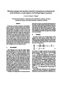
ments of h11, 21, 13, 23, 15, 25, . . .j from the axis with relative powers of h1, 1, 1y9, 1y9, 1y25, 1y25, . . .j. Each order itself carries a correspondingly scaled analog phase modulation h11, 21, 13, 23, 15, 25, . . .j 3 fsx, yd It is then a simple matter to isolate the first positive diffracted order with a spatial filter (or pinhole). Transforming the transmitted light field a second time with a second lens produces a wave front with the desired phase, spatially inverted about the optic axis, along with preapplied tilt, which can be easily removed by repositioning of the second lens laterally. To achieve binary phase modulation in practice we use a FLCSLM that consists of a square array of 256 3 256 square pixels. This results in the familiar effects of aliasing owing to pixelation and attenuation in the Fourier plane by a factor corresponding to the Fourier transform of the square pixel function. Aliasing is the more important of these two effects, as it means that the higher diffracted orders can appear close to the desired 11 order in the Fourier plane. Here we choose an overall tilt across the square aperture of 88p rad in the x direction and 120p rad in the y direction. The resulting zeroth-order zone Fourier-plane intensity pattern is shown in Fig. 1 for a f lat wave front fsx, yd 0, with various diffraction orders indicated: The 11 order also overlaps the 263 order. Also shown in the figure is the outline of an appropriate spatial filter that would allow the 11 order to pass predominantly, i.e., a circular hole of diameter 100f lyD, where f is the focal length of the lens, D is the lateral size of the FLCSLM array, and l is the wavelength. This system was implemented by use of the apparatus shown in Fig. 2. An expanded 532-nm laser beam is split by a polarizing beam splitter (PBS) into a reference and a signal beam. The signal beam is ref lected by a second PBS onto the FLCSLM (a 256 3 256 by 15-mm square-pixel silicon backplane device; Displaytech Model SLM 256P). Ref lected light from the FLCSLM that passes straight through that same PBS has binary phase modulation according to the pattern displayed on the FLCSLM and is Fourier transformed by the first lens. In the back focal plane a 2.67-mm circular aperture (equivalent to 107f lyD) is used as a spatial filter, allowing the 11 order through to be Fourier transformed a second time by the second lens. 1998 Optical Society of America
1850
OPTICS LETTERS / Vol. 23, No. 23 / December 1, 1998
Fig. 1. Fourier-plane intensity pattern for a binarized tilted plane wave.
Fig. 2.
modified Fourier-transform algorithm,7 and a typical binary phase pattern was produced as shown in Fig. 4 for Dyr0 10. We simulated a circular aperture by filling corners of the square FLCSLM with an alternating checkerboard pattern. These regions produce diffracted orders in the corners of the zone shown in Fig. 1 that are blocked by the pinhole and hence do not reach the output plane. Interferograms and intensity images of the output plane are shown in Fig. 5 for a single phase screen scaled for the two cases of Dyr0 10 and Dyr0 30. As can be seen, the intensity is almost constant in the central region. For the case of Dyr0 30 the intensity is signif icantly reduced in the regions of largest phase gradient. In the binary phase mask these regions contain the spatial frequencies that would be wholly or partially attenuated by the spatial filter, and hence the intensity at these points in the output aperture is reduced. Further inaccuracies can also be introduced, as light from other diffraction orders will be well spread and can pass through the spatial filter. The evidence for these effects in Fig. 5 is minimal. To predict the accuracy of this wave-front generation method numerically, we introduce generation efficiency h. We take a function, Asx, ydexpfjDfsx, ydg, that has the amplitude of the predicted generated wave front but a phase Dfsx, yd equal to the difference between that of the generated and the desired wave fronts. We then calculate the generation efficiency h as the Strehl ratio of this difference wave front by comparing its on-axis
Experimental setup: BS, beam splitter.
The signal and the reference beams then interfere on a CCD camera in the image plane of the FLCSLM produced by the two lenses, which permits us to measure both the intensity and the phase of the generated wave front. Figure 3(a) shows an interferogram taken for a nominally f lat wave front fsx, yd 0 (the reference beam has been tilted to show approximately three fringes). The residual aberrations of the optical system were calculated from a sequence of such interferograms obtained at phases separated by 2py3 rad. The inverse of the aberration was then added to all subsequent wave fronts, effectively canceling the residual system aberrations. Figure 3(b) shows the straight fringes produced in the interferogram when the f lat generated wave front is corrected in this way. To demonstrate the effectiveness of the system for generating useful wave fronts, we attempted to produce phase screens corresponding to optical transmission through Kolmogorov turbulence.6 Such phase screens are useful in modeling imaging through turbulent media such as the atmosphere. The screens are fractal in nature, and we can scale them to any aperture size by multiplying by a factor sDyr0 d5/6 , where D is the physical aperture diameter and r0 is the Fried coherence length. Phase screens were generated according to a
Fig. 3. Interferograms of the basic optical system (a) before and ( b) after correction.
Fig. 4. Binary pattern for generating a wave front with Dyr0 10.
December 1, 1998 / Vol. 23, No. 23 / OPTICS LETTERS
Fig. 5. (a), ( b) Interferograms and (c), (d ) intensity images for (a), (c) Dyr0 10 and (b), (d) 30.
1851
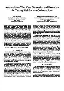
phase screens as calculated for our system parameters with a spatial filter diameter of 100f lyD. It can be seen that the generation eff iciency is higher than 86% for values of Dyr0 up to 30. Although the binary phase modulation of the FLCSLM’s is independent of wavelength, the position of the 11 order will be wavelength dependent and the output wave front will have a wavelength-dependent tilt superimposed upon it. Compensation by introduction of a wavelength-dependent pretilt to the input light is possible with a dispersive element such as a prism or a diffraction grating that causes the 11 orders to overlap. However, the output wave front will then have the same phase modulation at all wavelengths rather than a true optical path-length modulation. Operation of the devices in a mode that is insensitive to the input polarization is also possible,8 as any zeroth order that is produced in the Fourier plane is masked by the spatial filter. Likewise, fast binary amplitude-modulating spatial light modulator devices such as the digital micromirror device9 could be used instead of the FLCSLM, as the large zeroth order will again be masked by the spatial filter. We have described a method for generating arbitrary known wave fronts and, in particular, Kolmogorov phase screens. We also demonstrated how a FLCSLM can be used to measure and correct for aberrations introduced by the optical system itself. We have introduced a measure of efficiency of wave-front generation and shown that the effects of Kolmogorov turbulence can be efficiently simulated for a range of aperture sizes. This particular FLCSLM was found to be capable of operating at speeds of up to 2.5 kHz, and we used this feature to simulate evolution of Kolmogorov turbulence phase screens over time. This research was funded by the U.K. Biotechnology and Biological Sciences Research Council. M. A. A. Neil’s e-mail address is
[email protected].
Fig. 6. Wave-front generation efficiency as a function of aperture size.
intensity in the focal plane of a lens with that which would be produced with a f lat wave-front across the same pupil P and containing the same overall power. This measurement takes into account both amplitude and phase errors in the wave front that are introduced by this method and can be expressed mathematically as Ç2 Ç RR Asx, ydexpfjDfsx, ydgdxdy P ∏ . h ∑RR (2) RR 2 dxdy jAsx, ydj dxdy P P
Figure 6 shows how the wave-front generation efficiency h varies with Dyr0 for ten randomly generated
References 1. G. D. Love, Appl. Opt. 36, 1517 (1997). 2. D. J. Cho, S. J. Thurman, J. T. Donner, and G. M. Morris, Opt. Lett. 23, 969 (1998). 3. S. E. Broomfield, M. A. A. Neil, E. G. S. Paige, and G. G. Yang, Electron. Lett. 28, 22 (1992). 4. J. Gourlay, S. Samus, P. McOwan, D. G. Vass, I. Underwood, and M. Worboys, Appl. Opt. 33, 8251 (1994). 5. W. H. Lee, in Progress in Optics, E. Wolf, ed. (Elsevier, New York, 1978), Vol. XVI, Chap. 3. 6. J. W. Goodman, Statistical Optics (Wiley, New York, 1985). 7. R. G. Lane, A. Glindemann, and J. C. Dainty, Waves Random Media 2, 209 (1992). 8. S. T. Warr and R. J. Mears, Electron. Lett. 31, 714 (1995). 9. D. M. Monk and R. D. Gale, Microelectron. Eng. 27, 489 (1995).