the number of coefficients, the LUT based multiplication scheme needs less resources ..... multiplication but with a signed interpretation of the the input vector xL.
Dynamically Reconfigurable FIR Filter Architectures with Fast Reconfiguration Martin Kumm, Konrad M¨oller and Peter Zipf Digital Technology Group University of Kassel, Germany Email: {kumm, konrad.moeller, zipf}@uni-kassel.de
Abstract—This work compares two finite impulse response (FIR) filter architectures for FPGAs for which the coefficients can be reconfigured during run-time. One is a recently proposed filter architecture based on distributed arithmetic (DA) and the other is based on a LUT multiplication scheme. Instead of using the common internal configuration access port (ICAP) for reconfiguration which is able to change the logic as well as the routing, it is sufficient to reconfigure only the logic in the regarded architectures. This is realized by using the configurable look-up table (CFGLUT) primitive of Xilinx that allows reconfiguration times which are orders of magnitudes faster than using ICAP. The resulting FIR filter architectures achieves reconfiguration times of typically less than 100 ns. They can be reconfigured with arbitrary coefficients that are only limited by their length and word size. As their resource consumptions depend on different parameters of the filter, a detailed comparison is done. It turned out that if the input word size is greater than approximately half the number of coefficients, the LUT based multiplication scheme needs less resources than the DA architecture and vice versa.
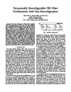
I. I NTRODUCTION The finite impulse response (FIR) filter is one of the most fundamental components in digital signal processing. Its block schematic is shown in Fig. 1. Due to the high amount of multiply-accumulate (MAC) operations, the computational power of many real-time applications can only by realized by using the parallel nature of of application specific integrated circuits (ASICs) like field programmable gate arrays (FPGAs). To reduce the performance gap between ASICs and FPGAs, digital filters were one of the driving forces to push embedded multipliers or DSP blocks into the FPGA fabric. The price for those fixed coarse-grained blocks are their inflexibility and limited quantity. However, in many applications like for digital filters, the multiplications have to be performed only with constants that may be only reconfigured from time to time which can be used to reduce the complexity. Examples are multi-stage filters for decimation or interpolation like polyphase FIR filters [1] or frequency variable filters as needed in telecommunications, digital audio, medical, radar, sonar and instruments [2]. On ASICs, one has to realize the reconfiguration on a very low-level, e. g., by introducing multiplexers in the circuit to select between different configurations. Several methods for reconfigurable multiplier blocks (ReMB) for reconfigurable FIR filters have been proposed in the last decade [1], [3]–[6]. Of course, these circuits can be also mapped to FPGAs [4], [6], but they are very limited in the number of different filter
Multiplier Block
Fig. 1.
FIR filter in transposed form
configurations. Furthermore, todays FPGAs provide standard interfaces for reconfiguration like the internal configuration access port (ICAP) of Xilinx FPGAs. With ICAP, a reconfigurable logic region can be defined whose functionality can be exchanged during run-time by any circuit, i. e., the logic functions (LUT content) as well as the routing can be completely exchanged. However, in many applications like in the FIR filter case, the functionality of different configurations is very similar and only a few parameters are exchanged. A possibility to exchange only the logic without changing the complete routing on modern Xilinx FPGAs, namely the Virtex 5-7, Spartan 6, Kintex 7 and Artix 7, is given by the use of a configurable LUT (CFGLUT). It is very similar to the 16 bit shift register LUTs (SRL16) of older Xilinx FPGAs but has an input word size of five bit instead of four. One advantage of exchanging the logic only is, of course, the reduced reconfiguration memory. But much more important is the fact that there is no bandwidth limitation of a single reconfiguration port like ICAP, as the reconfiguration using CFGLUTs can be done in parallel. Each CFGLUT can be reconfigured in 32 clock cycles where the configuration clock is only limited by routing delays of the FPGA fabric. As each CFGLUT can be reconfigured in parallel, e. g., sourced from many block RAM resources, reconfiguration times in the order of 100 ns can be realized. Compared to ICAP, which has a single 32 bit port operating with up to 100 MHz [7], reconfiguration times are often in the order of microseconds or even milliseconds. A very generic tool flow for mapping parametrizable circuit configurations to tunable LUTs (TLUTs) like the CFGLUT or SRL16, which is called dynamic circuit specialization, was proposed by Bruneel et al. [8], [9]. Here, the FPGA routing of the circuit is fixed but parameters of the circuit, like the constants of an FIR filter, can be exchanged at run-time by performing a dynamic reconfiguration of the LUT content. However, this work concentrates on hand optimized low-level
implementations. A reconfigurable FIR filter that uses CFGLUTs was proposed in a recent work of our group [10]. In that work, the FIR filter was realized using distributed arithmetic (DA) [11], [12], as it is naturally realized using LUTs. To map these LUTs to the typically smaller CFGLUTs, a LUT reduction technique [13] was used. Surprisingly, the reconfigurable FIR filters were even more hardware efficient than the fixed coefficient (nonreconfigurable) DA filters generated by Xilinx Coregen (16% less slices on average). The achieved reconfiguration times were 80 ns on average and 106 ns in the worst case. A totally different reconfigurable FIR filter can be built by replacing each constant multiplier of Fig. 1 with a reconfigurable one. A reconfigurable FPGA multiplier using distributed RAM or block RAM was proposed by Wiatr et al. [14]. It is based on a LUT based multiplication scheme which was introduced by Chapman [15], [16] and later extended by Wirthlin [17]. In both methods, any number of coefficient sets can be configured which are only constrained by the configuration memory. However, both methods are based on totally different architectures. Their resource consumptions depend on the input word size, the coefficient word size as well the number of coefficients in a different manner. Thus, the main contribution of this work is a detailed comparison of a reconfigurable FIR filter built from reconfigurable LUT multipliers [14] realized with state-of-the-art CFGLUTs, with the DA based reconfiguration scheme [10]. In addition to that, a detailed comparison with partial reconfiguration using the ICAP interface is done. The remainder of the paper is organized as follows. In Section II, the CFGLUT is introduced as base for the discussed architectures. Then, the reconfigurable DA filter architecture [10] is introduced in Section III as needed for further comparisons. The reconfigurable LUT based multiplication scheme as well as the corresponding filter architecture are presented in Section IV. A detailed comparison of both architectures is done in Section V, followed by the experimental results and concluding remarks.
CFGLUT5
I0
CDI CE CCLK
Fig. 2.
O6 CDO
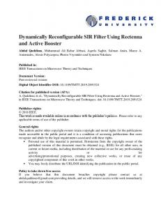
Block diagramm of the CFGLUT5 primitive
utilize the same slice resources as a standard 6-input LUT. Note that the clock of the output flip flop of that slice (if used) is in the same clock domain as CCLK. Back portability to older Xilinx FPGA architectures can be achieved by using the SRL16 primitive (and adjusting the input word size). Alternatively, block RAMs which are available on nearly every modern FPGA can also be used as reconfigurable LUTs. Then, additional resources are needed for address counter and data multiplexers (if a single port RAM is used) [14]. III. D ISTRIBUTED A RITHMETIC FIR A RCHITECTURE The fundamental operation of an FIR filter is the inner product of two vectors, yn = c · x =
N −1 X
cn xn ,
(1)
n=0
where vector x consists of time shifted scalars of the filter input and vector c consists of the coefficients. When each input sample xn is coded in two’s complement format xn =
BX x −2
2b xn,b − 2Bx −1 xn,Bx −1
(2)
b=0
where xn,b denotes the b’th bit of xn , we can insert (2) in (1) and exchange the two resulting sums: ! BX N −1 x −2 X yn = cn 2b xn,b − 2Bx −1 xn,Bx −1 (3)
II. RUN - TIME R ECONFIGURABLE LUT S The interface of the run-time reconfigurable CFGLUT is shown in Fig. 2. Besides the LUT inputs I0. . . I4 and outputs O5 and O6, it provides a reconfiguration interface consisting of the signals configuration data in (CDI), configuration data out (CDO), clock enable (CE) and configuration clock (CCLK). It can be used as a single 5-input LUT using O6 only or as two 4-input LUTs with shared inputs by setting I4 = 1 and using O5 and O6. In order to perform a change of the output function(s), 32 bit of configuration data have to be clocked into CDI while CE is set to high. The previous configuration is shifted out at CDO which can be used to cascade a series of CFGLUTs. However, each CDI input can be programmed in parallel leading to a reconfiguration time of 32 clock cycles. The speed of the configuration clock is only limited by the FPGA routing fabric. The CFGLUT can be mapped into the FPGA by using the HDL primitive CFGLUT5 [18] which
O5
I4
=
n=0 BX x −2 b=0
2b
b=0 N −1 X
N −1 X
n=0
n=0
cn xn,b −2Bx −1
|
{z
=f (˜ xN b )
}
|
cn xn,Bx −1 {z
=f (˜ xN Bx −1 )
(4)
}
Now, the inner product can be represented as a sum of bit shifted results of the function f (˜ xN b )=
N −1 X
cn xn,b .
(5)
n=0
Function f (˜ xN ˜N b ) only depends on the N -bit vector x b = T (x0,b , x1,b , . . . , xN −1,b ) which contains the b’th bit of the (time shifted) elements of x. It can be precomputed and stored in a single LUT with N inputs. The storage requirement of the LUT is BfN · 2N bit, where N Bf denotes the output word size of the N -input LUT f (˜ xN b ). This output word size depends on the coefficient word size
CFGLUT5 I0
RLUT
O5
I4
CDI CE CCLK
CDI CE
O6 CDO
CFGLUT5
RLUT
I0
O5
I4 CDI CE
RLUT
O6 CDO
CFGLUT5 I0
Filter Select
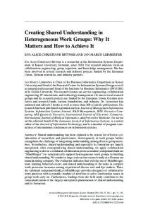
Fig. 3.
Reconf. Circuit
CDI SEL CCLK
O5
I4 CDI CE
O6 CDO
Architecture of the reconfigurable distributed arithmetic FIR filter
of the given filter. For a maximum coefficient word size of Bc , the maximum LUT output word size can be obtained by evaluating (5) with xn,b = 1 ∀ n, leading to BfN = Bc + dlog2 (N )e .
(6)
A. Mapping the LUT into smaller partial LUTs The input size and, therefore, the memory requirements of the LUT can be reduced by splitting the sum in (5) into several smaller sums bN/Lc−1 (l+1)L−1
f (˜ xN b )=
X
X
l=0
n=lL
|
N −1 X
cn xn,b +
cn xn,b
(7)
n=N −L0
{z
=fl (˜ xL b )
}
|
{z
0
=fbN/Lc (˜ xL b )
}
Fig. 4. A reconfigurable LUT realization of f (˜ xN b ) using single CFGLUT5 primitives
� � inputs for xn are reduced to M = N2 inputs of zn , thus, the storage requirements are approximately halved by introducing bN/2c adder. All adders in Fig. 3 are followed by pipeline registers (not shown) forming a pipelined adder tree. Furthermore, most of the left shift operations can be moved towards the output of the output adder tree for word size reduction. The reconfigurable LUTs (RLUTs) of Fig. 3 already contain CFGLUTs for reconfiguration which are shown in detail in Fig. 4. Each CFGLUT5 computes two bits of f (˜ xL b ) which are further processed in a pipelined adder tree (pipeline registers not shown) according to (7).
with L < N . Each of the functions IV. LUT M ULTIPLIER BASED FIR A RCHITECTURE
(l+1)L−1
fl (˜ xL b)=
X
cn xn,b
(8)
n=lL
can be realized as an L-input LUT. If N is not dividable by L, one additional LUT of input size L0 = N mod L is necessary, which is represented with the last term in (7). Now, L can be chosen to fit into the input word size of the FPGA LUT. Choosing L = 4 or L = 5 allows a direct mapping to CFGLUTs. Furthermore, the LUT storage requirement for the N -input LUT f (˜ xN b 0) is reduced from 0 BfN · 2N bits to bN/Lc · BfL · 2L + BfL · 2L bits. This memory reduction is paid by bN/Lc additional adders. Note that for a fixed L, this realization style grows linear with the number of filter taps N in contrast to (5) which grows exponentially. An analytic comparison of the LUT input size revealed that it is always advantageous to use a CFGLUT as two 4-input LUTs instead of a single 5-input LUT [10]. The resulting reconfigurable DA architecture [10] is shown in Fig. 3. Here, an additional pre-processing stage of registers and adders is used to exploit the inherent coefficient symmetry of common linear phase FIR filters. By doing that, the N LUT
A LUT based realization of (1) can also be achieved by simply mapping each product cn · xn to a Bx -input LUT. Then, the storage requirement would be Bc · 2Bx for each LUT. Like for the DA, the LUT content can be represented as a sum of partial products. Hence, a similar LUT reduction method as used in (7) can be applied, leading to the constant multiplication scheme of Chapman [16]. Let us consider one of�the �Bx ×Bc multiplications of (1). It can be divided into K = BLx smaller products by rearranging the partial sum terms: ! BX x −2 b Bx −1 cn · xn = cn 2 xn,b − 2 xn,Bx −1 | {z } b=0
Bc ×Bx mult.
= cn
L−1 X b=0
+ cn
2b xn,b + cn
2L−1 X
2b xn,b + . . .
b=L KL−2 X
b=(K−1)L
b
KL−1
2 xn,b − 2
xn,KL−1
= cn
L−1 X
L
b
2 xn,b +2 cn
L−1 X
b=0
|
{z
=g(ˆ xL n,l )
... + 2
(K−1)L
CFGLUT5 I0
b
2 xn,b+L + . . .
b=0
} · cn
| L−2 X
{z
=g(ˆ xL n,l )
CDI CE CCLK
}
CDI CE
2 xn,b+(K−1)L − 2 {z
| =
O6 CDO
! b
L−1
CFGLUT5
xn,KL−1
I0
b=0
K−2 X
O5
I4
=g 0 (ˆ xL n,l )
(K−1)L 0 L 2lL g(ˆ xL g (ˆ xn,l ) n,l ) + 2
O5
I4
}
CDI CE
O6 CDO
(9)
l=0
CFGLUT5
Each of the K − 1 function terms g(ˆ xL l ) represents a Bc × L unsigned multiplication with input vector x ˆL n,l = T (xn,lL , xn,lL+1 , . . . , xn,lL+L−1 ) : g(ˆ xL n,l )
= cn ·
x ˆL n,l
O5
I4 CDI CE
O6 CDO
(10)
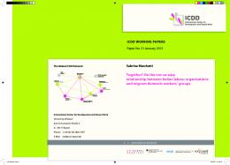
The function term g 0 (ˆ xL l ) for the MSB represents the same multiplication but with a signed interpretation of the the input vector �x ˆL n,l�in case a singed multiplication is performed. Thus, Bx K = L multiplications of size Bc × L are necessary to perform the Bc × Bx multiplication. In case that Bx is not dividable by L, xn has to be sign extended to KL bits with K = dBx /Le. Now, each partial product can be realized by an L-input LUT with 2L precomputed products. Hence, L can be chosen to fit the LUT input size of the specific FPGA. In the reconfigurable multiplier of Wiatr [14], L was chosen to fit the address word size of distributed RAM or block RAM, in this work, L is chosen to the input word size of the CFGLUT. Finally, the bit shifted partial products have to be added. The resulting reconfigurable constant LUT multiplier is shown in Fig. 5. A pipelined adder tree is used to improve the performance (pipeline registers not shown in Fig. 5). The applied pipelining does not lead to much extra resources, as most of the flip-flops (FFs) can be mapped to the otherwise unused FFs of slices realizing full adders. Note that the bit shifts after the LUTs can also be moved to later stages of the adder tree to reduce the word size. The LUT storage � � requirements are now reduced from Bc · 2Bx bits to BLx BgL 2L bits, where BgL = Bc + L .
I0
(11)
denotes the output word size of the partial LUTs. As for the reconfigurable DA architecture there are many CFGLUTs with identical inputs, so it is again better to configure the CFGLUT to two independent 4-input LUTs. The precomputed LUT contents are listed in Table I. Now, several reconfigurable multipliers can be used to build a reconfigurable FIR filter. For that, all the multipliers in the dashed box in Fig. 1 are replaced by reconfigurable ones. Like for the reconfigurable DA architecture, coefficient symmetry is assumed for the proposed design, too. To realize that, only M = dN/2e of the multipliers are implemented which are shared between two of the so called structural adders shown below the multiplier block in Fig. 1. For negative symmetry, the corresponding structural adders are replaced by subtractors.
Fig. 5.
LUT based constant multiplication with a pipelined adder graph
TABLE I LUT CONTENTS OF THE CFGLUT MULTIPLIER USING L = 4 LUT address
g 0 (ˆ xL n,l ) (MSB LUT)
g(ˆ xL n,l ) (other LUTs)
0000 0001 ...
0 · cn 1 · cn ...
0 · cn 1 · cn ...
0111 1000 1001
7 · cn −8 · cn −7 · cn
7 · cn 8 · cn 9 · cn
... 1111
... −1 · cn
... 15 · cn
V. C OMPARISON OF FIR A RCHITECTURES A. Resource Consumption To estimate the FPGA resource consumption the required CFGLUTs and adders are evaluated for both architectures. It can be taken as indicator for selecting the architecture for a given filter, which is specified with the number of taps (N ), the input word size (Bx ) and the coefficient word size (Bc ). For the reconfigurable DA architecture Bx + 1 M -input LUTs are required, where each of them contains dM/Le L-input LUTs with an output word size of BfL (see Fig. 3 and Fig. 4). Using L = 4, two output bits can be computed with a single CFGLUT, leading to a total number of CFGLUTs of � � NCFGLUT,DA = (Bx + 1) dM/4e Bf4 /2 = (Bx + 1) dM/4e dBc /2 + 1e .
(12)
In contrast to the reconfigurable DA filter, the LUT multiplier FIR architecture consists of M multipliers, realized as Bx -input LUT. Each of the Bx -input LUT is built from dBx /Le L-input LUTs with an output word size of BgL . When two output bits are computed with a single CFGLUT by setting
L = 4, the total number of CFGLUTs is � � NCFGLUT,LUTM = M dBx /4e Bg4 /2 = M dBx /4e dBc /2 + 2e .
CFGLUT5
I0 I4
(13) Block RAM
(14)
It can be seen that the required CFGLUTs are very similar for both architectures. To estimate the architecture with the least CFGLUTs, we assume that M and Bx are both dividable by four, and Bc is dividable by two. Then, the LUT multiplier architecture needs less CFGLUTs compared to the DA architecture when the following unequation is true:
CDI CE CCLK
O5 O6 CDO
CFGLUT5 I0 O5 I4
Controller
CDI CE CCLK
O6 CDO
NCFGLUT,LUTM < NCFGLUT,DA Fig. 6.
M Bx /4(Bc /2 + 2) < (Bx + 1)M/4(Bc /2 + 1) Bx < Bc /2 + 1
Control architecture for the reconfiguration of CFGLUTs
(15)
Hence, if the input word size Bx is less than approximately half the coefficient word size Bc , the LUT multiplier architecture needs less CFGLUTs and vice versa. Besides the used CFGLUTs a large amount of adders are necessary. For the DA FIR architecture M adders are necessary in the pre-processing stage as well as an adder tree with Bx adders in the post-processing (see Fig. 3). Each of the Bx + 1 RLUTs consist of dM/Le adders, resulting in
For the LUT multiplier based architecture, all partial product LUTs except the MSB LUT can use the same configuration data, as they all represent the multiplication of one 4 bit input with the same coefficient. Only the MSB LUT has to be reconfigured with a different configuration because of the sign bit for signed multiplication. Each partial product has an output word size of BgL , so the storage requirement is
NADD,DA = M + Bx + (Bx + 1) dM/4e .
As it can be seen, the required storage is independent of the input word size Bx and the influence of the coefficient word size is Bc /2 for both architectures. But for the LUT multiplier based architecture, the memory requirement is approximately eight times higher than for distributed arithmetic. Thus, the reconfigurable DA architecture is always the best in terms of memory requirements.
(16)
For the LUT multiplier architecture, N −1 structural adders are needed to compute the filter output from the multiplier results (see Fig. 1). Each of the M reconfigurable multipliers consists of dBx /Le adders, resulting in NADD,LUT = N − 1 + M dBx /4e .
(17)
To give an estimate for the architecture with the least adders, we assume that M and Bx are both dividable by 4 and N = 2M . Then, the LUT multiplier architecture needs less adders when the following unequation is true: NADD,LUT < NADD,DA 2M − 1 + M Bx /4 < M + Bx + (Bx + 1)M/4 3M − 4 < 4Bx
(18)
As each adder typically consists of several slices, where each slice contains up to four CFGLUTs, the adder estimation is much more significant than the CFGLUT estimation. Hence, as a rule of thumb, if the input word size is greater than approximately half the number of coefficients, the LUT multiplier architecture needs less resources and vice versa. B. Configuration Memory With configuration memory we mean the storage requirements for a single configuration. Thus, it has to be multiplied by the number of different configurations to get the total memory requirement. For the DA architecture all RLUTs shown in Fig. 3 have the same content. As each of the CFGLUT needs 32 bit of configuration data, the storage requirement is SDA = 32 · dM/4e dBc /2 + 1e bit .
(19)
SLUTM = 64 · M dBc /2 + 2e bit .
(20)
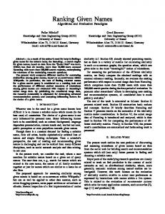
VI. R ECONFIGURATION C IRCUIT The reconfiguration circuit can be built from a block RAM or distributed RAM and a simple controller. It is shown in Fig. 6, together with two CFGLUTs. An input vector filt_sel is used which can arbitrarily select a filter coefficient set and an enable signal rec_en is used to start the reconfiguration. Then, a 5 bit counter is used to address a sequence of 32 reconfiguration words. The RAM address can then be composed of the filt_sel which addresses the higher bits together with the five output bits of the counter to address the lower bits by a simple concatenation. Note that during the reconfiguration process, the output of the multiplier is not valid. This problem can be fixed by a clock enable signal at the output register of the multiplier, which leads to a neglect of the input during reconfiguration. Alternatively each CFGLUT can be doubled as it was proposed in previous work [10]. It can be reconfigured with the new coefficient while the other CFGLUT is processing data. A multiplexer is used to switch between the two CFGLUTs to achieve a glitch free data processing. VII. R ESULTS Two synthesis experiments were made to evaluate the resource usage, speed and reconfiguration times of the different
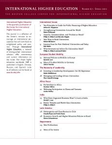
architectures. In the first experiment, the LUT based multiplier architecture as well as the DA architecture are synthesized for different filter lengths and input word sizes. In the second experiment, we used ICAP for the partial reconfiguration of highly optimized filter instances to compare the resource overhead and configuration times. A VHDL code generator was developed in Matlab for the different architectures. All synthesis results were obtained after place & route using Xilinx ISE v13.4 with the design goal ’speed’ for a Virtex 6 FPGA (XC6VLX75T-FF784). A. Comparison of CFGLUT based Architectures To compare the two discussed architectures, several different reconfigurable filters were synthesized. To ease the comparison with other work, we used a benchmark set of nine filters with N = 6 up to N = 151 coefficients which were already used in previous publications [10], [19]–[21]. The coefficients have a maximum word size of Bc = 17 bit and are available online as MIRZAEI10 N [22]. The input word size was varied from Bx = 8 . . . 32 bit in steps of 8 bit. Of course, any filter of the same symmetry up to Bc , Bx and N can be reconfigured. Lower word sizes have to be sign extended while unused coefficients have to be set to zero. The same clock was used for the filter as well as for reconfiguration. Detailed synthesis results are listed in Table II, which shows the configuration memory per instance (S), the number of Slices, the maximum clock frequency fclk as well as the reconfiguration time Trec = 32/fclk for both methods. On average, both architectures achieve nearly equally low reconfiguration times of 69.94 ns and 65.94 ns and fast clock frequencies of 472.4 MHz and 494.2 MHz, respectively. As expected from Section V-B, the reconfiguration memory of the LUT multiplier architecture is approximately eight times higher compared to the DA based architecture. A comparison of the resources is visualized in Fig. 7 which shows the percentage slice improvement of the LUT multiplier based architecture over the DA based architecture. Hence, in case positive values are shown, the LUT architecture is the better choice and vice versa. As expected from Section V-A, the LUT multiplier based architecture performs better for smaller filter instances when dN/2e < Bx . Exceptions from that rule can be explained by the other parts of the filter, e. g., an unbalanced adder tree with 2n−1 < x < 2n inputs may need as many slices as a balanced one with x = 2n inputs due to pipelining. Up to 35% slice reductions can be achieved by using the LUT multiplier architecture for small filters but the DA architecture is still advantageous for larger filter instances requiring up to 40% less slices. B. Comparison with ICAP The standard partial reconfiguration scheme supported by the Xilinx ISE tools provides that a reconfigurable region of the FPGA is reserved which can be exchanged by any circuit in run-time using the ICAP interface. This implies that the reconfigurable region is large enough to include the largest configuration. In contrast to the discussed CFGLUT
TABLE II S YNTHESIS RESULTS FOR THE PROPOSED RECONFIGURABLE LUT MULTIPLIER FIR FILTER IN COMPARISON WITH RECONFIGURABLE DA FIR FILTER [10] Reconf. FIR DA [10]
Reconf. FIR LUT (proposed)
Bx N
S [bit]
Slices
fclk Trec [MHz] [ns]
S [bit]
Slices
fclk Trec [MHz] [ns]
8 8 8 8 8 8 8 8 8
6 10 13 20 28 41 61 119 151
320 640 640 960 1280 1920 2560 4800 6080
145 199 191 365 374 627 835 1487 1813
570.5 492.4 601.3 496.3 525.2 522.7 543.2 499.5 395.4
56.1 65.0 53.2 64.5 60.9 61.2 58.9 64.1 80.9
2112 3520 4928 7040 9856 14784 21824 42240 53504
93 143 188 297 406 595 837 1668 2156
647.3 575.0 608.6 534.8 551.9 573.4 499.5 504.0 415.3
49.4 55.6 52.6 59.8 58.0 55.8 64.1 63.5 77.1
16 16 16 16 16 16 16 16 16
6 10 13 20 28 41 61 119 151
320 640 640 960 1280 1920 2560 4800 6080
253 372 353 635 707 1071 1341 2594 4256
622.7 552.8 545.3 467.7 525.8 521.9 413.7 348.3 410.5
51.4 57.9 58.7 68.4 60.9 61.3 77.3 91.9 78.0
2112 3520 4928 7040 9856 14784 21824 42240 53504
179 262 370 544 782 1108 1575 3257 4149
576.7 572.4 522.2 518.4 540.3 487.8 463.8 480.3 428.8
55.5 55.9 61.3 61.7 59.2 65.6 69.0 66.6 74.6
24 24 24 24 24 24 24 24 24
6 10 13 20 28 41 61 119 151
320 640 640 960 1280 1920 2560 4800 6080
371 522 535 939 1029 1558 1958 4047 5802
550.7 556.2 470.8 573.7 416.5 383.6 372.0 355.4 385.2
58.1 57.5 68.0 55.8 76.8 83.4 86.0 90.0 83.1
2112 3520 4928 7040 9856 14784 21824 42240 53504
303 431 587 884 1172 1691 2332 5047 6515
536.2 498.3 545.6 531.6 482.9 467.1 435.0 393.1 380.7
59.7 64.2 58.7 60.2 66.3 68.5 73.6 81.4 84.1
32 32 32 32 32 32 32 32 32
6 10 13 20 28 41 61 119 151
320 640 640 960 1280 1920 2560 4800 6080
490 734 704 1130 1419 1965 2570 4889 7170
524.9 480.3 507.1 517.9 430.7 376.5 358.6 302.9 391.1
61.0 66.6 63.1 61.8 74.3 85.0 89.2 105.6 81.8
2112 3520 4928 7040 9856 14784 21824 42240 53504
320 531 771 1026 1482 2091 3601 6523 8016
512.3 485.4 495.8 473.9 442.9 446.0 401.6 377.2 386.7
62.5 65.9 64.5 67.5 72.3 71.7 79.7 84.8 82.8
architectures, both logic and routing can be replaced. On the one hand, each configuration can be optimized like a static design which is very resource efficient. On the other hand, the storage requirement is much larger which also leads to longer reconfiguration times due to the sequential ICAP interface. The ICAP interface has a word size of 32 bit and can be operated with up to 100 MHz [7]. However, this speed is a theoretical maximum which can only be achieved with some effort [23]. Reconfiguration clocks of 94.5 MHz were reported by using a block RAM cache that was closely located at the ICAP [24]. To get the maximum performance out of the ICAP approach, we used the reduced pipelined adder graphs (RPAG) algorithm [25] which is a state-of-the-art optimization method for fixed coefficient multiplier blocks as needed for FIR filters. All multiplications by constants are mapped to add/subtract and bit shift operations in a pipelined way. It was shown in previous work [20], [21], [26], [27], that this method outperforms DA based filters as well as LUT based multipliers in the case that input word sizes of more than 12 bit are used. As
Slice improvement [%]
Slice improvement [%]
40 20 0 −20 −40
6
10
13
20
28
41
61
119 151
40 20 0 −20 −40
6
10
13
Filter length N
Slice improvement [%]
Slice improvement [%]
20 0 −20 10
13
20
28
41
61
119 151
Filter length N
61
119 151
61
119 151
40 20 0 −20 −40
6
10
13
20
28
41
Filter length N
(c) Input word size Bx = 24 bit Fig. 7.
41
(b) Input word size Bx = 16 bit
40
6
28
Filter length N
(a) Input word size Bx = 8 bit
−40
20
(d) Input word size Bx = 32 bit
Slice improvement of the reconfigurable FIR filter based on LUT multipliers in comparison with the reconfigurable DA FIR filter
TABLE III C OMPARISON OF A SINGLE FILTER MIRZAEI10 41 WITH Bx = 16 BIT USING ICAP RECONFIGURATION AND THE CFGLUT METHODS Method
S [bit]
Slices
RPAG [25] with ICAP Reconf. FIR DA [10] Reconf. FIR LUT
746496 1920 14784
502. . . 569 1071 1108
fclk [MHz]
Trec [ns]
386.7. . . 448.8 233280 521.9 61.3 487.8 65.6
the optimization heavily depends on the numeric coefficient values, ten different filters were designed with the same length as the mid size benchmark filter MIRZAEI10 41 and an input word size of 16 bit. These served as realistic configurations which can be reconfigured via ICAP. The results are summarized in Table III. The number of slices using RPAG optimized FIR filters varied for the different filter instances from 502. . . 569. Hence, a reconfiguration region with a capacity of 569 slices has to be reserved. The reconfiguration is organized in frames of 80 slices, thus, eight frames have to be reserved where each frame contributes with 93312 bit, leading to a reconfiguration memory requirement of SICAP = 746496 bit per filter instance. Compared to the CFGLUT-based methods, a factor of 388 and 50 more reconfiguration memory is necessary, respectively. Assuming that the full performance of ICAP can be used, the reconfiguration takes Trec = SICAP /32 · 10 ns = 233 µs. Thus, compared to the slowest CFGLUT methods with 65.5 ns, the ICAP reconfiguration is a factor of 3556 slower. The price for these fast reconfiguration times and low memory requirements is paid by a slice overhead of 88% and 95%, respectively. VIII. C ONCLUSION We analyzed two reconfigurable FIR filter architectures based on the CFGLUT primitives which can be mapped to all modern FPGAs of Xilinx. The first one is based on a
recently proposed method based on distributed arithmetic [10], the second one uses several instances of a reconfigurable LUT multiplier [14] to build a reconfigurable multiplier block as needed in the FIR filter. Similarities between the different approaches were derived as both methods uses similar arithmetic transformations to map large LUTs to several smaller LUTs by the use of additional adders. It turned out that less CFGLUTs, and, in most of the cases, less slices are needed for the LUT based multiplier architecture in the case that the input word size is greater than approximately half the number of coefficients and vice versa. Both methods have reconfiguration times and memory requirements which are about four orders of magnitudes faster than using partial reconfiguration via the ICAP interface which is paid by approximately twice the amount of slices. R EFERENCES [1] M. Faust, O. Gustafsson, and C.-H. Chang, “Reconfigurable Multiple Constant Multiplication Using Minimum Adder Depth,” in Conference Record of the Forty Fourth Asilomar Conference on Signals, Systems and Computers (ASILOMAR), 2010, pp. 1297–1301. [2] Lowenborg and Johansson, “Minimax Design of Adjustable-bandwidth Linear-phase FIR Filters,” IEEE Transactions on Circuits and Systems I: Regular Papers, vol. 53, no. 2, pp. 431–439, 2006. [3] S. S. Demirsoy, A. Dempster, and I. Kale, “Design Guidelines for Reconfigurable Multiplier Blocks,” in IEEE International Symposium on Circuits and Systems (ISCAS), 2003. [4] S. S. Demirsoy, I. Kale, and A. Dempster, “Efficient Implementation of Digital Filters Using Novel Reconfigurable Multiplier Blocks,” in Conference Record of the Thirty-Eighth Asilomar Conference on Signals, Systems and Computers, 2004, pp. 461–464. [5] P. Tummeltshammer, J. Hoe, and M. Puschel, “Time-Multiplexed Multiple-Constant Multiplication,” IEEE Transactions on ComputerAided Design of Integrated Circuits and Systems, vol. 26, no. 9, pp. 1551–1563, Sep. 2007. [6] R. Gutierrez, J. Valls, and A. Perez-Pascual, “FPGA-Implementation of Time-Multiplexed Multiple Constant Multiplication based on Carry-Save Arithmetic,” in International Conference on Field Programmable Logic and Applications (FPL), 2009, pp. 609–612.
[7] Xilinx, Inc., Partial Reconfiguration User Guide, Oct. 2010. [8] K. Bruneel, W. Heirman, and D. Stroobandt, “Dynamic Data Folding with Parameterizable FPGA Configurations,” Transactions on Design Automation of Electronic Systems, vol. 16, no. 4, pp. 43:1–43:29, Oct. 2011. [9] K. Bruneel, “Efficient Circuit Specialization for Dynamic Reconfiguration of FPGAs,” Ph.D. dissertation, Universiteit Gent, 2011. [10] M. Kumm, K. M¨oller, and P. Zipf, “Reconfigurable FIR Filter Using Distributed Arithmetic on FPGAs,” in IEEE International Symposium on Circuits and Systems (ISCAS), 2013, pp. 2058–2061. [11] A. Crosisier, D. J. Esteban, M. E. Levilio, and V. Riso, “Digital Filter for PCM Encoded Signals,” United States Patent No. 3777130, 1973. [12] S. Zohar, “New Hardware Realizations of Nonrecursive Digital Filters,” IEEE Transactions on Computers, vol. 22, no. 4, pp. 328–338, 1973. [13] S. A. White, “Applications of Distributed Arithmetic to Digital Signal Processing: A Tutorial Review,” IEEE ASSP Mag., vol. 6, no. 3, 1989. [14] K. Wiatr and E. Jamro, “Implementation of Multipliers in FPGA Structures,” International Symposium on Quality Electronic Design, pp. 415–420, 2001. [15] K. D. Chapman, “Fast Integer Multipliers Fit in FPGAs,” Electronic Design News, 1994. [16] K. Chapman, “Constant Coefficient Multipliers for the XC4000E,” Xilinx Application Note, 1996. [17] M. J. Wirthlin, “Constant Coefficient Multiplication Using Look-Up Tables,” Journal of VLSI Signal Processing, vol. 36, no. 1, pp. 7–15, Jan. 2004.
[18] Xilinx, Inc., Xilinx Virtex-5 Libraries Guide for HDL Designs, 2009. [19] S. Mirzaei, R. Kastner, and A. Hosangadi, “Layout Aware Optimization of High Speed Fixed Coefficient FIR Filters for FPGAs,” Int. Journal of Reconfigurable Computing, vol. 2010, pp. 1–17, 2010. [20] M. Kumm and P. Zipf, “High Speed Low Complexity FPGA-based FIR Filters Using Pipelined Adder Graphs,” in International Conference on Field-Programmable Technology (FPT), 2011, pp. 1–4. [21] U. Meyer-Baese, G. Botella, D. Romero, and M. Kumm, “Optimization of High Speed Pipelining in FPGA-based FIR Filter Design Using Genetic Algorithm,” in Proceedings of SPIE, 2012. [22] FIRsuite, “Suite of constant coefficient FIR filters,” 2013. [Online]. Available: http://www.firsuite.net [23] S. Liu, R. N. Pittman, A. Forin, and J. L. Gaudiot, “On Energy Efficiency of Reconfigurable Systems With Run-time Partial Reconfiguration,” in IEEE International Conference on Application-specific Systems Architectures and Processors (ASAP), 2010, pp. 265–272. [24] M. Liu, W. Kuehn, Z. Lu, and A. Jantsch, “Run-time Partial Reconfiguration Speed Investigation and Architectural Design Space Exploration,” in International Conference on Field Programmable Logic and Applications (FPL), 2009, pp. 498–502. [25] M. Kumm, P. Zipf, M. Faust, and C.-H. Chang, “Pipelined Adder Graph Optimization for High Speed Multiple Constant Multiplication,” in IEEE Int. Symposium on Circuits and Systems (ISCAS), 2012, pp. 49–52. [26] U. Meyer-Baese, J. Chen, C. H. Chang, and A. G. Dempster, “A Comparison of Pipelined RAG-n and DA FPGA-based Multiplierless Filters,” in IEEE Asia Pacific Conference on Circuits and Systems (APCCAS), 2006, pp. 1555–1558. [27] M. Kumm, D. Fangh¨anel, K. M¨oller, P. Zipf, and U. Meyer-Baese, “FIR Filter Optimization for Video Processing on FPGAs,” EURASIP Journal on Advances in Signal Processing, vol. 2013, no. 1, p. 111, 2013. [Online]. Available: http://asp.eurasipjournals.com/content/2013/1/111