This work studies the dynamics, control and synchronization of hyperchaotic Lorenz-stenflo ... adaptive controller for control and synchronization of chaotic system in the ...... Conference on Decision and Control, , San Diego, Calif, USA, PP 1500-1501 (1997). ... Journal of Bifurcation and Chaos, 20 (4) PP 1201-1208 (2010).
International Journal of Chaos, Control, Modelling and Simulation (IJCCMS) Vol.6, No.1/2/3/4, December 2017
DYNAMICS, ADAPTIVE CONTROL AND EXTENDED SYNCHRONIZATION OF HYPERCHAOTIC SYSTEM AND ITS APPLICATION TO SECURE COMMUNICATION Onma O. S1 and Akinlami J.O2 1
Nonlinear Dynamics Research Group, Department of Physics, Federal University of Agriculture, Abeokuta, Nigeria 2
Department of Physics, Federal University of Agriculture Abeokuta, Nigeria
ABSTRACT This work studies the dynamics, control and synchronization of hyperchaotic Lorenz-stenflo system and its application to secure communication. The proposed designed nonlinear feedback controller control and globally synchronizes two identical Lorenz-stenflo hyperchaotic systems evolving from different initial conditions with unknown parameters. Adaptive synchronization results were further applied to secure communication. The numerical simulation results were presented to verify the effectiveness of the designed nonlinear controller and its success in secure communication application.
KEYWORDS Hyperhaos, control, synchronization, Secure Communication
1. INTRODUCTION Chaotic systems are characterized by their complex dynamical behaviuor particularly their extreme sensitivity to initial conditions and parameters variation which make their behaviour long-term unpredictable. Therefore, the idea to control and synchronize two chaotic systems has been considered as illogical and impossible [1]. The year 1990 marked a turning point in the study of chaotic dynamics when the idea of chaos control and synchronization was first proposed by Pecoral and Carrol [2], and it was shown that synchronization is not only possible but it has wide potential application in secure communication, engineering, physical, chemical, biological and financial systems, and information science [3-5]. Synchronization involves the linking of one system trajectories to the corresponding trajectories of the other such that both systems remain in step with each other (mimics) through the transmission of signal [6]. The coupling of these systems is usually called drive (master) and response (slave) systems [7]. Its numerous applications in secure communication has been one of the main motivating factor, where the basic idea is to mask the information bearing signal to be transmitted with chaotic signal that exhibits broad band feature [8-10]. A wide variety of approaches have been developed and reported in the literature to achieve chaos synchronization in the couple chaotic and hyperchaotic systems such as; time-delay feedback method [11], active control method [12-13], impulsive method [14], linear state error feedback method [15], adaptive control method [16-19]), backstepping technique [20-23] (see the references there in). Most of these approaches are based on exactly knowing the system structure DOI:10.5121/ijccms.2017.6501
1
International Journal of Chaos, Control, Modelling and Simulation (IJCCMS) Vol.6, No.1/2/3/4, December 2017
and parameters. But in many practical situations, some or all of these systems’ parameters are unknown. Also, these parameters can change from time to time. Therefore, the derivative of adaptive controller for control and synchronization of chaotic system in the presence of unknown parameters is an important issue [24], that made adaptive control method more advantageous in practice over the other approaches mention above. Though the adaptive control method is easy to manipulate, it still has the following limitation; the controller designed by this method usually have high or fixed signals strength and too large. As we know, the actual transmission of the signals is always associated with the signals’ amplification and reduction. Also, one always expected to achieve the final synchronization by using the relatively smaller signals. Thus the adaptive control can be improved by reducing the signal strength and the complexity in controller to minimize the energy consumption.In view of this, the present work is focused on the following: the dynamics and qualitative properties of hyperchaotic Lorenz-Stenflo system, designing of adaptive control method for controlling hyperchaoticLorenz-Stenflo system with fully unknown parameters to control to equilibrium point, design via adaptive nonlinear extended scheme control feedback input that capable of synchronizing two identical hyperchaotic LorenzStenflo systems evolving from different initial conditions and its application to secure communication. The control and synchronization based on this technique are simple and easy to implement in practical applications in some real systems.
2. DESCRIPTION OF LORENZ-STENFLO SYSTEM The mathematical interest in this work is the hyperchaotic Lorenz-Stenflo system described by the first order differential equations of the form given in equation (1) below;
x&1 = a( x 2 − x1 ) + bx 4 x& 2 = x1 (c − x3 ) − x 2
(1)
x& 3 = x1 x 2 − dx 3 x& 4 = − x1 − ax 4
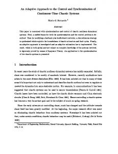
Where x1 , x 2 , x3 and x 4 are the state variables of the system and a , b, c and d are the real constant parameter of the system. System (1) exhibits hyperchaotic behavior when a = 1.0, b = 1.5, c = 26.0 and d = 0.7 and the phase portraits of the attractor is given in Fig.1. 45
15
40
10
35
5
30
0
25
x2
x3
20
-5
20
-10
15
-15
10
-20
5
-25
0 -8
-6
-4
-2
0 x1
(a)
2
4
6
8
-8
-6
-4
-2
0
2
4
6
8
x1
(b)
2
International Journal of Chaos, Control, Modelling and Simulation (IJCCMS) Vol.6, No.1/2/3/4, December 2017
x3 45 40 35 30 25 20 15 10 5 0
-8
-6
-4
-2 x1
0
2
4
6
8
-20
-15
-10
-5
0
5
10
15
20
25
x2
(c) Figure1. Phase portraits of Loren- Stenflo hyperchaotic system attractor with the parameter values; a = 1.0, b = 1.5, c = 26.0 and d = 0.7
3. BASIC DYNAMICS OF LORENZ-STENFLO HYPERCHAOTIC SYSTEM To derive the equilibrium point for Lorenz-Stenflo hyperchaotic system (1), when a ≠ 0 , b ≠ 0 , c ≠ 0 and d ≠ 0 , we solve the sets of equations in system (1). By solving system (1), we let;
x&1 = 0 , x& 2 = 0 , x&3 = 0 and x& 4 = 0 (condition for stability) Hence;
a( x2 − x1 ) + bx4 = 0
(2)
x1 (c − x3 ) − x2 = 0
(3)
x1 x2 − dx3 = 0
(4)
− x1 − ax4 = 0
(5)
Solving equations; (5), (3), (4) and (2) respectively we get;
x1 = −ax4 , x2 = −ax4 (c − x3 ) , x3 =
− a( x2 − x1 ) ( ax 4 ) 2 (c − x3 ) and x4 = b d
3.1 CONDITION FOR EQUILIBRIUM For hyperchaotic Lorenz-Stenflo system (1) to be in equilibrium, the following condition must be satisfy; x1 = x2 = x3 = x4 = 0. But solving the sets of equations in system (1) {i.e., equations, (2), (3), (4) and (5)}, x1 ≠ x2 ≠ x3 ≠ x4 , provided that a ≠ b ≠ c ≠ d ≠ 0 , which is a contradiction. Thus, there is no equilibrium point for hyperchaotic Lorenz-Stenflo system (1). Hence, control to equilibrium point E0 (0,0,0,0) and synchronization of hyperchaotic LorenzStenflo system (1) in the presence of system’s disturbances and unknown parameters is quiet interesting that needed to be address.
3
International Journal of Chaos, Control, Modelling and Simulation (IJCCMS) Vol.6, No.1/2/3/4, December 2017
4. ADAPTIVE CONTROL OF HYPERCHAOTIC LORENZ-STENFLO (LS) SYSTEM 4.1 DESIGN OF THE ADAPTIVE CONTROLLER In order to design the control function ui (t ) , ( i = 1, 2,3,4 ) using adaptive control method, we assume that the real parameters a , b, c and d in equation (1) are unknown. We now consider the controlled system as follow;
x&1 = a( x 2 − x1 ) + bx 4 + u1 (t ) x& 2 = x1 (c − x3 ) − x 2 + u 2 (t )
(6)
x& 3 = x1 x 2 − dx 3 + u 3 (t ) x& 4 = − x1 − ax 4 + u 4 (t ) Where ui (t ) , (i = 1,23,4) are the control function to determined. According to the Lyapunov stability theory, we choose the following Lyapunov function;
~ ~ 1 V = ( x12 + x 22 + x32 + x 42 + a~ 2 + b 2 + c~ 2 + d 2 ) 2 ~
~
(7)
~
Where a~ = a − a , b = b − b , c~ = c − c , d = d − d and a , b , c , d are the estimated values of these unknown parameter respectively. The time derivative of equation (7) is given in equation (8) below.
~ ~& ~ ~& V& = x1 x&1 + x 2 x& 2 + x 3 x& 3 + x 4 x& 4 + a~a~& + b b + c~c~& + d d
(8)
In order to ensure that the controlled system (6) converges at the origin (0,0,0,0) asymptotically at a desire time, the controllers ui (t ) are choosing as follows:
u1 (t ) = − a ( x 2 − x1 ) − bx 4 − x1 u 2 (t ) = − x1 (c − x3 ) u 3 (t ) = − x1 x 2 + dx3 − x 3
(9)
u 4 (t ) = x1 + ax 4 − x 4
V& = x1 [a ( x 2 − x1 ) + bx4 + u1 (t )] + x 2 [ x1 (c − x3 ) − x 2 + u 2 (t )] + x3 [ x1 x 2 − dx3 + u 3 (t )] + x 4 [− x1 − ax4 + u 4 (t )] ~ ~ + a~ (−a& ) + b (−b& ) + c~ (−c& ) + d (−d& ) = x1 [a ( x 2 − x1 ) + bx 4 + u1 (t )] + x 2 [ x1 (c − x3 ) − x 2 + u 2 (t )] + x3 [ x1 x 2 − dx3 + u 3 (t )] + x 4 [− x1 − ax 4 + u 4 (t )] ~ + a~ (−a& + x1 x 2 − x12 − x 42 ) + b (−b& + x1 x 4 ) + c~ (−c& + x 2 ) + ~ d (− d& − x32 )
(10)
4
International Journal of Chaos, Control, Modelling and Simulation (IJCCMS) Vol.6, No.1/2/3/4, December 2017
The following parameter update laws were chosen;
a = x1 x 2 − x12 − x 42 b = x1 x 2
(11)
c = x2 d = − x32 Substituting equation (11) into equation (10) yields;
V& = − x12 − x 22 − x 32 − x 42 < 0
(12)
According to the Lyapunov stability theory, the above condition ensures that the controlled system (6) stabilizes at the origin (0,0,0,0) at a chosen time with the designed controllers in equation (9) and the parameter update laws given by equation (11).
4.2 NUMERICAL SIMULATION RESULTS Appling fourth-order Runge-Kutta algorithm with the initialcondition x1 (0) = 0.8 , x 2 (0) = 0.6 ,
x3 (0) = −0.9 , x4 (0) = −0.8 , a time sizes of 0.001 and fixing the parameter values as in figure 1. The result obtained show that the state variables move hyperchaotically with time when the controllers are deactivated and when the controllers are switched on at t = 50 the state variables are converges or stabilized at the origin (0,0,0,0) according to the Lyapunov stability theory. The results are display in Figure 2. 8 6 4
x1
2 0 -2 -4 -6 -8 0
10
20
30
40
50
60
70
80
90
100
time
(a) 25 20 15
x2
10 5 0 -5 -10 -15 -20 0
10
20
30
40
50
60
70
80
90
100
time
(b)
5
International Journal of Chaos, Control, Modelling and Simulation (IJCCMS) Vol.6, No.1/2/3/4, December 2017 45 40 35 30
x3
25 20 15 10 5 0 -5 0
10
20
30
40
50
60
70
80
90
100
time
(c) 4 3 2
x4
1 0 -1 -2 -3 -4 0
10
20
30
40
50
60
70
80
90
100
time
(d) Figure2. Time responses of the state variables ( x1 , x2 , x3 , x4 ) for hyperchaotic Loren-Stenflo system when the controller is activated at t = 50 to stabilize at the origin.
5. ADAPTIVE CONTROL FOR SYNCHRONIZATION OF HYPERCHAOTIC LORENZ-STENFLO (LS) SYSTEM 5.1 DESIGN OF ADAPTIVE CONTROLLER FOR SYNCHRONIZATION OF HYPERCHAOTIC LORENZ-STENFLO SYSTEM In this section, we synchronized two identical hyperchaotic Loren-Stenflo systems evolving from two different initial conditions. In order to obtain a partial strict- feedback, system (1) is rearranged as follows;
x& 4 = − x1 − ax 4 x&1 = a ( x 2 − x1 ) + bx 4 x& 2 = x1 (c − x 3 ) − x 2 x& 3 = x1 x 2 − dx 3
(13)
We let x4 = x1 , x1 = x2 , x2 = x3 and x3 = x4 , then equation (13) takes the following forms;
x&1 = − x 2 − ax1 x& 2 = a ( x3 − x 2 ) + bx1 x& 3 = x 2 (c − x 4 ) − x 3 x& 4 = x 2 x3 − dx 4
(14)
6
International Journal of Chaos, Control, Modelling and Simulation (IJCCMS) Vol.6, No.1/2/3/4, December 2017
Equation (14) is called the drive (master) and equation (15) is the response (slave).
y& 1 = − y 2 − ay1 + u1 (t ) y& 2 = a ( y 3 − y 2 ) + by1 + u 2 (t )
(15)
y& 3 = y 2 (c − y 4 ) − y 3 + u 3 (t ) y& 4 = y 2 y 3 − dy 4 + u 4 (t )
Where ui (t ) (i = 1,2,3,4) are the control functions to be designed with the assumption that the parameters a , b, c and d are unknown constant. Our objective is to design an appropriate adaptive control inputs vector ui (t ) to stabilize the errors vector of the state variables at the origin (0,0,0,0) and also to make the state variables of the response (slave) system (15) to track the ones of the drive (master) system (14) with the parameter update laws at any chosen time. We define the synchronization errors vector between the drive (master) system (14) and the response (slave) system (15) as follows;
ei = yi − xi or yi =e i + xi
(16)
Where i = 1,2,3,4 The subtraction of equation (14) from equation (15) is the result of the following errors vector:
e&1 = −e 2 − ae1 + u1 (t ) e& 2 = a (e3 − e 2 ) + be1 + u 2 (t )
(17)
e&3 = ce2 − ( x 2 e 4 + x 4 e2 + e2 e 4 ) − e3 + u 3 (t ) e& 4 = x 2 e3 + x3 e 2 + e 2 e3 − de 4 + u 4 (t ) We consider the Lyapunov function as follows;
~ ~ 1 V = (e12 + e22 + e32 + e42 + a~ 2 + b 2 + c~ 2 + d 2 ) 2 ~
(18)
~
~ = a − a , b = b − b , c~ = c − c and d = d − d are the estimate values these unknown Where a parameters a , b, c and d respectively. The time derivative of equation (18) along the trajectories of the errors vector and estimate values of the constant parameter gives equation (19) below. ~ ~& ~ ~& V& = e1 e&1 + e 2 e& 2 + e3 e&3 + e 4 e& 4 + a~a~& + b b + c~c~& + d d
(19)
We substituted equation (17) in equation (19) to give equation (20) below.
V& = e1 [−e2 − ae1 + u1 (t )] + e2 [a (e3 − e2 ) + be1 + u 2 (t )] + e3 [ce2 − ( x 2 e4 + + x 4 e2 + e2 e4 ) − e3 + u 3 (t )] + e4 [ x 2 e3 + x3 e2 + e2 e3 − de4 + u 4 (t )] + ~ ~ a~ (− a& ) + b ( −b& ) + c~ ( −c& ) + d ( −d& )
7
International Journal of Chaos, Control, Modelling and Simulation (IJCCMS) Vol.6, No.1/2/3/4, December 2017
= e1[−e2 − ae1 + u1 (t )] + e2 [a (e3 − e2 ) + be1 + u 2 (t )] + e3 [ce2 − ( x 2 e4 + x 4 e2 + e2 e4 ) − e3 + u 3 (t )] + e4 [ x 2 e3 + x3 e2 + e2 e3 − de4 + u 4 (t )] + a~ (− a& − e12 + e2 (e3 − e2 )) ~ ~ + b (−b& + e e ) + c~ (−c& + e e ) + d (− d& − e 2 ) 1 2
2 3
(20)
4
a , b , c and d takes the place of a , b, c and d respectively. To ensure that the errors vector converges to equilibrium point E0 (0,0,0,0) asymptotically, the condition V& < 0 must be satisfied. From equation (17), we selected the controllers as follows:
u1 (t ) = e2 + ae1 − e1 u 2 (t ) = −a (e3 − e2 ) − be1 − e2 u 3 (t ) = −ce2 + x 2 e4 + x 4 e2 + e2 e4
(21)
u 4 (t ) = de4 − ( x 2 e3 + x3 e2 + e2 e3 ) − e4 And the parameter update estimation laws as;
a& = −e12 + e 2 (e3 − e 2 ) − a b& = e1e2 − b c& = e2 e3 − c
(22)
d& = −e 42 − d Substituting equation (22) into equation (20) yield;
~ ~ V& = −e12 − e22 − e32 − e42 − a~ 2 − b 2 − c~ 2 − d 2 < 0
(23)
In order to minimize energy consumption and controller complexity, we introduce the weight ε i to the designed controller in equation (21) as follows;
u1 (t ) = [e2 + ae1 − e1 ]ε 1 u 2 (t ) = [−a (e3 − e2 ) − be1 − e2 ]ε 2 u 3 (t ) = [−ce2 + x 2 e4 + x 4 e2 + e2 e4 ]ε 3
(24)
u 4 (t ) = [de4 − ( x 2 e3 + x3 e2 + e2 e3 ) − e4 ]ε 4 Where ε i ( i = 1, 2,3,4 ) are the weight added to the designed controllers. For simplicity,
ε 1 = ε 2 = ε 3 = ε 4 = ε was chosen. The errors vector converges to the origin (0,0,0,0) asymptotically in line with the Lyapunov stability theory. Also the drive (master) system (14) is synchronized with the response (slave) system (15) with the controllers (21) and (24)and the parameter update law (22).
8
International Journal of Chaos, Control, Modelling and Simulation (IJCCMS) Vol.6, No.1/2/3/4, December 2017
5.2 NUMERICAL SIMULATION RESULTS To verify the feasibility and effectiveness of the designed controllers (21) and (24) and the parameter update laws (22), we simulate the dynamics of the drive (master) system (14) and the response (slave) system (15) by employing fourth-order Runge-Kutta integration method to solve the systems of differential equations given by equations (14) and (15) respectively with the ( x1 , x2 , x3 , x4 ) = (0.5,0.6,0.6,0.8) , following initial conditions
( y1 , y 2 , y3 , y 4 ) = (−9.0,1.0,0.2,9.0) , a time size of 0.001 and fixed the real parameter values of the system as in figure 1. The results obtained shows that the error vector variable moves hyperchaotically with time when the controllers are switched off and when the controllers are activated at t = 50 as shown in figures 3 and 4, the error vector variables converges to the origin (0,0,0,0) and thereby guaranteeing the synchronization of systems (14) and (15). This is confirmed by the synchronization norm e given by;
e = e12 + e 22 + e32 + e 42
(25)
We observed from the numerical simulation results that the control strength and its complexity are reduced by 30% ( ε = 0.7 ) when the proposed extended adaptive control approach is applied (Figure 4), i.e. only about 70% of the strength of the usual adaptive control is needed to achieve complete synchronization. Thus this new method proposed in this work is an evident that the control strength weight ε is important by produces economics controllerswith low energy consumption which may be useful for practical application. However, the initial values of the parameter update laws (22) are chosen as follows; a1 (0) = 4.0 ,
b1 (0) = 6.0 , c1 (0) = 18.0 and d 1 = 3.0 . The parameter estimation values a , b , c and d converges to a = 1.0 , b = 1.5 , c = 26.0 and d = 0.7 respectively (see Fig. 5) as t → ∞ . 6 4 2
e1
0 -2 -4 -6 -8 -10 0
10
20
30
40
50
60
70
80
90
100
time
(a) 15 10 5
e 2
0 -5 -10 -15 -20 0
10
20
30
40
50
60
70
80
90
100
time
(b) 9
International Journal of Chaos, Control, Modelling and Simulation (IJCCMS) Vol.6, No.1/2/3/4, December 2017 30 20 10
e3
0 -10 -20 -30 -40 0
10
20
30
40
50
60
70
80
90
100
60
70
80
90
100
time
(c) 30
20
e4
10
0
-10
-20
-30 0
10
20
30
40
50 time
(d) 45 40 35
ee
30 25 20 15 10 5 0 0
10
20
30
40
50
60
70
80
90
100
time
(e) Figure 3: Error dynamics between two identical hyperchaotic Loren-Stenflo systems when the controller is activated at t = 50 . 6 4 2
e 1
0 -2 -4 -6 -8 -10 0
10
20
30
40
50
60
70
80
90
100
time
(a) 10
International Journal of Chaos, Control, Modelling and Simulation (IJCCMS) Vol.6, No.1/2/3/4, December 2017 15 10 5
e2
0 -5 -10 -15 -20 0
10
20
30
40
50
60
70
80
90
100
time
(b) 30 20 10
e3
0 -10 -20 -30 -40 0
10
20
30
40
50
60
70
80
90
100
time
(c) 30
20
e4
10
0
-10
-20
-30 0
10
20
30
40
50
60
70
80
60
70
80
90
100
time
(d) 45 40 35
ee
30 25 20 15 10 5 0 0
10
20
30
40
50
90
100
time
(e) Fig. 4: Error dynamics between two identical hyperchaotic Loren-Stenflo systems when the controller is activated at t = 50 with ε = 0.7 .
11
International Journal of Chaos, Control, Modelling and Simulation (IJCCMS) Vol.6, No.1/2/3/4, December 2017 4 2 0
x1,y1
-2 -4 -6 -8 -10 0
10
20
30
40
50
60
70
80
90
100
60
70
80
90
100
time
(a) 8 6 4 2 x2,y2
0 -2 -4 -6 -8 -10 0
10
20
30
40
50 time
(b) 25 20 15
x3,y3
10 5 0 -5 -10 -15 -20 0
10
20
30
40
50
60
70
80
90
100
time
(c) 45 40 35
x4,y4
30 25 20 15 10 5 0 0
10
20
30
40
50
60
70
80
90
100
time
(d) Figure 5: Time responses of the state variables of drive (master) and response (slave) systems when the controller is switch on at t = 50 Note: Red is the drive (master) system and Green is the response (slave) system. 12
International Journal of Chaos, Control, Modelling and Simulation (IJCCMS) Vol.6, No.1/2/3/4, December 2017 30
25
a,b,c,d
20
15
10
5
0 0
10
20
30
40
50
60
70
80
90
100
time
Figure 6: The time responses of the parameter estimation errors.
6. APPLICATION TO SECURE COMMUNICATION One of the most important applications of chaos synchronization in engineering is in secure communication, where the basic idea is to mask or modulate (encrypt) the information bearing signal to be transmitted with chaotic signal that exhibits broad band feature (see references [810]).The information signal is added i.e. masked to the output of a chaotic oscillator to produce unpredictable signal which is transmitted from the transmitter to the receiver. At the receiver the pseudo-random is generated through the inverse operation, original message is retrieved. In order for this scheme to properly work, the receiver must synchronize robustly enough so as to admit the small perturbation in the drive signal due to the addition of the message [25-26]. The power of information signal must be lower than that of chaotic signal to effectively bury the information signal. The signal from the master controls the slave system so as to synchronize it with the master and to carry the information
signal, just like any other communication scheme. The purpose of chaos secure communication is to hide message during transmission. In this chaotic masking scheme, encryption is achieved by combing the information signal with the chaotic carrier signal using mixing algorithm which is simply a function of information and chaotic carrier signals [27]. Here we demonstrate our secure communication scheme using the additive encryption masking scheme. The information signal is chosen to be a periodic function i (t ) = 5 sin 0.3t , with this choice the chaotic carrier x1 remain chaotic. The encrypted information is given by the masking algorithm ie (t ) = i(t ) + x1 . Consequently, the decrypted information id (t ) is given by the inverse function id (t ) = ie (t ) − y1 . The chaotic signal x1 of the master is transmitted to the slave via a coupling channel for synchronization between the master and the slave, the information signal i (t ) = 5 sin 0.3t is masked in the encrypted signal ie (t ) and transmitted to the receiver. The decrypted information id (t ) is extracted by inverse function. The numerical simulation results of the communication scheme are displayed in Figure 6.
13
International Journal of Chaos, Control, Modelling and Simulation (IJCCMS) Vol.6, No.1/2/3/4, December 2017 6
4
i(t)
2
0
-2
-4
-6 0
10
20
30
40
50
60
70
80
90
100
time
(a) 8 6 4
ie(t)
2 0 -2 -4 -6 -8 0
10
20
30
40
50
60
70
80
90
100
time
(b) 12 10 8 6
id(t)
4 2 0 -2 -4 -6 -8 -10 0
10
20
30
40
50
60
70
80
90
100
time
(c)
14
International Journal of Chaos, Control, Modelling and Simulation (IJCCMS) Vol.6, No.1/2/3/4, December 2017 6 4 2
er
0 -2 -4 -6 -8 -10 0
10
20
30
40
50
60
70
80
90
100
time
(d) Figure7: (a) information signal i (t ) ; (b) encrypted signal ie (t ) ; (c) decrypted signal (t=50), id (t ) (d) decrypted error er = i(t ) − ie (t ) .
7. CONCLUSION In this work the adaptive control method has been applied to control and synchronize Lorenzstenflo system with fully unknown parameters in the presence of system’s disturbancesand further extended the synchronization results to secure communication. The designed adaptive nonlinear controllers control Lorenz-stenflo system to equilibrium point E0 (0,0,0,0) according to the Lyapunov stability theory and globally synchronized two identical Lorenz-stenflo systems evolving from different initial conditions. The presence of the weight ( ε i.e., the control signal) introduced to the controllers play a major role in the synchronization by overcomes the limitations of large signals and controller complexity in the normal adaptive control. This approach suggested that only about 70% ( ε = 0.7 ) of the strength of the usual adaptive control is enough to achieve complete synchronization. We also observed from the numerical simulation results that the speed of synchronization depend on the value of ε , for large value of ε , the speed for achieve synchronization is high and to minimize the expenses, small value of the control strength ε should be adopted. In addition, one can easily change the value of ε according to the actual requirement. Hence, the introduction of weight to the usual controller as a signal control is of economic benefit that is suitable for practical implementation. Numerical simulations were given to demonstrate the effectiveness and efficiency of the proposed scheme. Thus, practical implementation of the proposed scheme shall be very useful and the future work shall focus on addressing this problem.
REFERENCES [1]
Liu S.Y, X and Zhu, S.J, Study on the chaos anti control technology in nonlinear vibration system. Journal of sound and vibration 310 (4-5): 855-864 (2008).
[2]
L.M. Pecora, T.L. Corral, Synchronization in chaotic systems. Phys. Rev. Lett. 64, 821-824 (1990).
[3]
C. Kyrtsou and W.C. Labys,Evidence for chaotic dependence between US inflation and commodity prices. Journal of Macroeconomics, vol. 28 (1), PP 256-266 (2006).
[4]
C. Kryrtsou and W.C. Labys,Detecting positive feedback in multivariate time series and US inflation, Physica A: Statistical Mechanics and its applications, vol.377 (1), PP 227-229 (2007).
[5]
S.H Kellert,In the wake of Chaos: Unpredictable order in Dynamical systems, University of Chicago Press, (1993). 15
International Journal of Chaos, Control, Modelling and Simulation (IJCCMS) Vol.6, No.1/2/3/4, December 2017
[6]
Nastaran Vasegh, Faarhad Khella, Chaos synchronization of chemical model. Journal of Applied science and technology 1(5), (2011).
[7]
Njah, A.N., Tracking control and synchronization of the new hyperchaotic Liu system via backstepping techniques. Nonlinear Dyn. 61, PP 1-9 (2009).
[8]
Kocarev, L., Chaos –based cryptography: A brief overview, IEEE Circuits and systems magazine, vol. 1, pp. 6-21 (2001).
[9]
Hasler, M., Synchronization of chaotic systems and transmission of information. International Journal of Bifurcation and chaos, vol.8, PP 647-659 (1998).
[10] Silva, C.P., A. M. Young, Introduction to chaos-based communications and signal processing, “Pro. IEEE Aerospace Conference”, PP.279-299 (2000). [11] Dianchen L, Aicheng W, Xiandon T., Control and synchronization of a new hyperchaotic system with unknown parameters. International journal of nonlinear science 6(3), PP 224-229 (2008). [12] Vincent, U. E., Chaos synchronization using active control and backstepping control: A Comparative Analysis. Non-linear Analysis: Theory and applications, 13, PP 256-261 (2008). [13] Bai, E. W., Longngren, K. E., Synchronization of two Lorenz systems using active control. Chaos Solitons and fractals 8(1), PP 51-58 (1997). [14] Li, C., Liao, X., Wong, K-W, Lag synchronization of hyperchaos with applications to secure communications, Chaos Solitons Fractals 183-193 (2005). [15] O.I. Olusola, U.E. Vincent, A.N. Njah, Synchronization, multistability and basin crisis in coupled pendula. Journal of sound and vibration, 329 PP 443-456 (2010). [16] M.T Yassen, Adaptive control and synchronization of a modified chua’s circuit system. Applied mathematics and computation 135, PP 113-128 (2003). [17] M. M. El-Dessoky, M.T. Yassen, Adaptive feedback control for chaos control and synchronization for new chaotic Dynamical system. Mathematical problems in Engineering. Vol. 2012, Article ID 347210, 12pages (2012). [18] Xingyuan Wang, Yaqin Wang, Adaptive control for synchronization of a four-dimensional chaotic system via a single variable. Nonlinear Dyn. 65 PP 311-316 (2011). [19] O.S. Onma, O.I. Olusola, A.N. Njah, Control and Synchronization of chaotic and hyperchaotic Lorenz system via extended adaptive control method. Far East Journal of Dynamical Systems, 28 (1) PP 1-32 (2016). [20] S. Onma Okpabi, Adelakun A.Oke, J.O. Akinlami, S.T Opeifa, Backstepping Control and Synchronization of hyperchaotic Lorenz-Stenflo system with application to secure communication. Far East Journal of Dynamical Systems, 29 (1) PP 1-23 (2017). [21] O. S. Onma, O.I. Olusola, A.N. Njah, Control and synchronization of chaotic and hyperchaotic Lorenz systems via extended backstepping techniques. Journal of nonlinear dynamics, vol. 2014, Article ID861727, 15 Pages (2014). [22] Olasunkanmi I., Olusola, Uchechukwu E. Vincent, Abdulahi N. Njah, Emad Ali, Control and synchronization of chaos in biological systems via backstepping design. International journal of nonlinear science. 11(1)PP121-128 (2011). [23] S. Mascolo, ” Backstepping design for controlling Lorenz chaos”, in proceedings of the 36th IEEE Conference on Decision and Control, , San Diego, Calif, USA, PP 1500-1501 (1997). 16
International Journal of Chaos, Control, Modelling and Simulation (IJCCMS) Vol.6, No.1/2/3/4, December 2017
[24] Zhigong, S., Wenzhi, Z., Gangquan, S., Adaptive synchronization design for uncertain systems in the presence of unknown parameters: Nonlinear Dyn. 72 PP 729-749 (2013). [25] Adelakun A.Oke, Adelakun A. Adisa, Onma O. Sunday, Bidirectional synchronization of two identical Jerk oscillators with memristor. International journal of Electrical, Electronics and Telecommunication Engineering, 45 (2) PP 2051-3240 (2014). [26] Aceng Sambas, Mada Sanjaya WS, Mustafa Mamat, Bidirectional coupling scheme of chaotic systems and its application in secure communication system. Journal of Engineering Science and Technology Review, 8 (2) PP 89-95 (2015). [27] M. Liu, J. Feng, C.K. Tse, A new hyperchaotic system and its circuit implementation. International Journal of Bifurcation and Chaos, 20 (4) PP 1201-1208 (2010). [28] Chittaranjan Pradhan, Ajay Kumar Bisoi’ Chaotic Vibrations AES Algorithm international journal of chaos , control modeling and simulation 2 ( 2013)
Authors Onma O.S Has B.Sc., (Physics), M.Sc in Theoretical Physics and a PhD Student of Theoretical/condensed matter Physics, department of physics, Federal university of Agriculture Abeokuta. His primary research interest is in nonlinear dynamics with application to chaos control, synchronization and secure communication.
J.O AKINLAMI Has B.Sc in Physics M.Sc and PhD in condensed matter physics. His primary research area are in theoretical and computational condensed matter physics. A senior lecturer in department of physics, Federal university of Agriculture, Abeokuta Nigeria
17