PROCEEDINGS OF ECOS 2015 - THE 28TH INTERNATIONAL CONFERENCE ON EFFICIENCY, COST, OPTIMIZATION, SIMULATION AND ENVIRONMENTAL IMPACT OF ENERGY SYSTEMS JUNE 30-JULY 3, 2015, PAU, FRANCE
Modelling and simulation of waste heat recovery systems for marine applications Asfaw Beyenea, Enrico Sciubbab, Lorenzo Toccic, Claudia Torod a
Dept. of Mechanical Engineering, San Diego State University, United States,
[email protected] b Dept. of Mechanical and Aerospace Engineering, University of Rome “Sapienza”, Italy,
[email protected] c Dept. of Mechanical and Aerospace Engineering, University of Rome “Sapienza”, Italy,
[email protected] d Institute of Environmental Geology and Geoengineering, National Research Council, Italy,
[email protected]
Abstract: Waste heat recovery systems have assumed an important role in the last decade as an effective way to improve fuel utilization in thermal engines, since they provide an opportunity to produce ecofriendly electrical power from an otherwise wasted energy source, leading to a reduction of the pollution and an increase of the overall system efficiency. In this scenario, Rankine cycle technology, based on simple Rankine cycle or Organic Rankine cycle (ORC), earned a good market position, thanks to its ability of producing additional electric power from relatively low-temperature heat sources (80 to 350°C); this feature makes these cycles a very suitable solution as bottomers to Internal Combustion Engines (ICE), geothermal sources, solar thermal modules and micro-gas turbines. This paper presents a waste heat recovery system specifically designed as a bottomer to ICE of different power range for marine applications, using a simple Rankine cycle or a Rankine cycle with ORC further bottoming. The particular application considered shows several advantages for the installation of a waste heat recovery system; in particular, the basically infinite availability of the cooling medium represented by the water sea, avoids any issues in the condenser design. A steady state model of the system is developed via the process simulator CAMEL-Pro™, in order to identify the most convenient configuration, from a thermodynamic point of view. A most interesting feature of this study with respect to previous works, is the comparison of the organic fluids R245fa and R600, widely recognized as two of the best candidate ORC fluids, within a configuration analysis that critically and analytically compares the improvements regeneration can possibly bring in the low grade regime. To this scope, different cycle configurations have been modeled, simulated and comparatively assessed, in order to figure out whether the more expensive Rankine bottoming ORC brings substantial improvements over the simpler Rankine cycle configuration and to investigate system behaviors in bottoming applications to atmospheric intake or turbo-charged marine Diesel engines. The paper shows how adding a bottoming ORC to the Rankine cycle improves the WHR system performance both in terms of recovered electric power (up to 8.11% and 2.67% respectively in small and large application size) and heat source utilization rate, since the heat source temperature could reach values as low as 70 °C when considering a Sulphur free fuel. In addition, R 245fa is to be preferred over the R 600 since it allows for the production of the same power considering lower values for the ORC top pressures.
Keywords: Bottoming Cycles, Organic Rankine Cycle, process simulation, thermodynamic analysis, Diesel waste heat recovery
1. Introduction Waste heat recovery (WHR) is a practice commonly used in energy conversion plants that allows to partially or completely convert the heat discharge of a primary cycle -that would 0
PROCEEDINGS OF ECOS 2015 - THE 28TH INTERNATIONAL CONFERENCE ON EFFICIENCY, COST, OPTIMIZATION, SIMULATION AND ENVIRONMENTAL IMPACT OF ENERGY SYSTEMS JUNE 30-JULY 3, 2015, PAU, FRANCE
otherwise leave the process as a “waste” and be released into the environment- into useful energy, either thermal or electrical. Such a system increases the overall efficiency, defined as the amount of useful final specific work produced per fuel unit mass, introducing several thermodynamic and economic advantages. Higher efficiency leads to the reduction of the increasingly regulated carbon dioxide emissions and fuel savings, since using otherwise discharged heat to produce additional work leads to a decrease of the fuel consumption. On the other hand, the heat recovery system presents a monetary additional installation cost that needs to be considered in the overall engineering feasibility analysis. According to Tchanche [17], WHR can be classified into 3 different groups with respect to their top temperature level: low (650 °C). Internal combustion engines, because of the relatively high temperature of the exhausts (approximately 600 °C for atmospheric intake ICE and 300-400°C for turbo-charged ICE), can be placed on the medium-high side, offering a great potential for heat recovery. The aim of this work is to recover heat from marine ICE exhaust gas. A yacht atmospheric intake Diesel engine (300 kW) and a vessel turbo-charged ICE (3x12.6 MW) have been investigated. The additional electric energy the system is able to provide is intended to be used on board, replacing a 15 kW electric generator for the yacht and providing part of the 10 MW electric power needs for the ship. The WHR system proposed is Rankine cycle based, considering different working fluids, depending on the thermodynamic conditions of the waste heat. For instance, it may result convenient to use water when the heat source is at a high temperature while organic fluids perform better for lower exhaust enthalpies. Several studies have been published on the selection of the proper fluid for each application, resulting in a wide accordance on the fact that simple Rankine cycles, using water as the operative fluid, work well when the heat source temperature is high (400-600 °C) while the same cycle, performed by organic fluids such as R245fa or R 600 (ORC), is more suitable when heat source temperature is low (80-150 °C). Vankeirsbilck [19], in his study on the comparison between Steam and organic Rankine cycle for small scale power generation, underlines how, for a low temperature heat source, the LMTD between hot and cold fluid is lower when using ORC, implying higher efficiency values; in addition, the opportunity ORC offer to expand the fluid avoiding superheating, increases the power density. Yu and Shu [20] analyzed a bottoming organic Rankine cycle applied to a 300 hp Diesel engine, considering as waste heat both the exhaust gas and the jacket water for different engine work conditions; their results show that it is possible to increase thermal efficiency up to 6.1% and produce power up to 15.5 kW. Zhang [21] studied a dual loop bottoming Organic Rankine Cycle applied to a 4 cylinders ICE; the high temperature (HT) loop recovers heat using R245fa as operative fluid, while the low temperature (LT) loop using R134a. The cycle performance has been calculated for several engine operational conditions, the conclusions being that the net power of the LT loop is higher than that of the HT and the efficiency increases of a rate of 14-16% in the peak effective thermal efficiency region while it can improve up to 38-43% at part load and in the high speed region. According to the author, such a cycle constitutes a promising scheme to recover heat from light-duty diesel engines. The ICE operative conditions constitute an important aspect that needs to be considered in the installation of a waste heat recovery system to produce electric power; in fact, while this cycle perfectly matches engines that work mainly at steady conditions, it suffers substantial performance derangements when installed on engines in which the operative conditions vary considerably over time. One of the reasons for the present work emphasis on WHR for 1
PROCEEDINGS OF ECOS 2015 - THE 28TH INTERNATIONAL CONFERENCE ON EFFICIENCY, COST, OPTIMIZATION, SIMULATION AND ENVIRONMENTAL IMPACT OF ENERGY SYSTEMS JUNE 30-JULY 3, 2015, PAU, FRANCE
marine applications is that usually both ships and yachts travel at fixed speed, resulting in steady conditions ideal for the operation of the HRSG. The relatively high power/volume density of these installations makes them suitable for many dynamic applications in which the plant weight and size have a fundamental role such as marine applications. When the heat rejection from the primary cycle is energetically rich, as it is for ships, it is also possible to consider the application of a double loop heat recovery system, in which at first high temperature fluid is converted into power in a regular Rankine cycle followed by an ORC in which the residual heat is used to produce additional electric power, increasing the overall recovery system efficiency. In order to reach this goal, 2 different fluids have been studied to investigate their characteristics in terms of thermodynamic properties and toxicity, to find out the most convenient ones for the applications object of this work. This study combines the comparison of two different organic fluids and the analysis of a dual loop recovery system, able to recover a high rate of the waste heat available. In addition, cycle top pressure has been investigated over a wide range, providing the reader with a deep understanding of the more convenient cycle thermodynamic condition. Marine application represents an uninvestigated field for what concern waste heat recovery; the main advantage with respect to other applications is represented by the condensing pressure of the working fluid that can reach low values because of the presence of the unlimited sink of relatively cold sea water to be used as the cooling medium, allowing for a high cycle specific work production. In automotive applications, for instance, the cycle cooling water needs to be cooled down itself using air, resulting in a lower expansion ratio and in a more complex system whose performance strongly depend on the temperature of the environment in which the system works. The WHR system modelling and simulation were performed using the CAMEL-Pro™ process simulator [1]; this software (CAlculation with Modular ELements) has been developed at the Department of Mechanical and Aerospace Engineering of the University of Roma Sapienza. The main feature of CAMEL is its modularity that enables users to expand the code by adding new components or by modifying the model of the existing ones. The code’s task is the simulation of energy conversion systems, and in particular, thermal power plants. CAMEL-Pro™ is equipped with a library of thermodynamic properties for the calculation of thermo-physical properties of fluids [6]. Models for the calculation of thermodynamic and transport properties of steam and organic fluids are implemented according to [6]. CAMEL has proved itself as a useful tool for both designing a new plant and analyzing the behavior of an existing one. The paper content is structured presenting a brief description of the configurations analyzed, the mathematical model considered for the components, a critical analysis of the results and the conclusions about the performance obtained for the simulated system.
2. Description of the systems configurations Different Rankine/ORC system configurations have been simulated in order to compare their performance with respect to the Rankine cycle, most commonly considered for waste heat recovery applications. Available heat exhaust specifications for both the ship and the yacht are reported in Table 1.
2
PROCEEDINGS OF ECOS 2015 - THE 28TH INTERNATIONAL CONFERENCE ON EFFICIENCY, COST, OPTIMIZATION, SIMULATION AND ENVIRONMENTAL IMPACT OF ENERGY SYSTEMS JUNE 30-JULY 3, 2015, PAU, FRANCE
Table 1: Heat sources available for WHR
Notice that the yacht, propelled by an atmospheric intake ICE, presents exhaust gas temperature way higher than the ship. In addition, while the boat allows for the recovery of the whole amount of the ICE exhaust gas, 50 % of the ship exhaust gas is already used to heat up the fuel and it gives the opportunity to recover heat from cooling water available at two different temperatures.
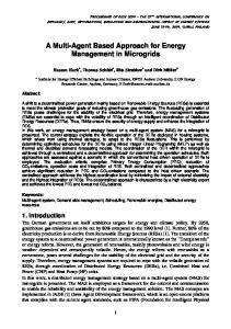
2.1. Rankine/ORC waste heat recovery system (RbORC) This configuration involves a Rankine cycle, which receives heat from the ICE exhausts and an ORC, whose fluid is vaporized by the gas exiting the Rankine cycle, as shown in Figure 1.
Figure 1: Rankine cycle bottoming ORC (RbORC)
2.2. Rankine/ORC regenerated waste heat recovery system (RbORCr) The RbORCr configuration introduces, with respect to the previous one, a regenerator (Figure 2), which pre-heats the pressurized organic fluid, using the fluid exiting the expander. This plant scheme was investigated in order to ascertain whether regeneration improves the cycle performance in terms of power output, discharged gas temperature and cycle efficiency.
3
PROCEEDINGS OF ECOS 2015 - THE 28TH INTERNATIONAL CONFERENCE ON EFFICIENCY, COST, OPTIMIZATION, SIMULATION AND ENVIRONMENTAL IMPACT OF ENERGY SYSTEMS JUNE 30-JULY 3, 2015, PAU, FRANCE
Figure 2: Rankine cycle bottoming ORC regenerated (RbORCr)
2.3. Rankine/ORC regenerated and integrated waste heat recovery system (RbORCri) The RbORCri configuration considers the introduction of a gas-organic fluid heat exchanger, in order to complete the ORC economization process (Figure 3). This plant scheme allows for a more complete exploitation of the heat source, forcing the exhaust to leave the system at a lower temperature with respect to the RbORCr one. In addition, the LMTD is lowered for what concern both HRSG and economizer, improving the component exergy efficiency, according to the Sama-Szargut second law rules [14].
Figure 3: Rankine cycle bottoming ORC regenerated & integrated (RbORCri)
2.4 ORC fed by hot temperature (HT) cooling water The vessel WHR system recovers heat also from the hot temperature cooling water coming from the engine cooling system, introduced in Table 1. Because of the heat source temperature value, a low top pressure ORC has been selected to produce additional electric power.
4
PROCEEDINGS OF ECOS 2015 - THE 28TH INTERNATIONAL CONFERENCE ON EFFICIENCY, COST, OPTIMIZATION, SIMULATION AND ENVIRONMENTAL IMPACT OF ENERGY SYSTEMS JUNE 30-JULY 3, 2015, PAU, FRANCE
Figure 4: ORC fed by hot temperature (HT) cooling water
3. Mathematical model of the components The CAMEL-ProTM process simulator has been used in order to perform the thermodynamic simulations. Being an object-oriented software, it requires the user to define the energy and mass balances in each component. A post processing analysis has been performed using the simulation data output, in order to define the efficiency of the different plant layouts.
3.1. Mass and energy balance equations The main thermodynamic equations considered to solve each component are shown, in this paragraph. 3.1.1. PUMP The pump provides work to the fluid, increasing its enthalpy, therefore its mass and energy balance are: 𝑚𝑖𝑛 = 𝑚𝑜𝑢𝑡 (1) 𝑃𝑃 =
𝑚∗(ℎ𝑃,𝑜𝑢𝑡 −ℎ𝑃,𝑖𝑛 )
(2)
𝜂𝑃
3.1.2. HRSG (HEAT RECOVERY STEAM GENERATOR) In Rankine cycle applied to WHR, heat is provided to the working fluid by the hot exhaust gases. Since a pinch point analysis was carried out, the energy balance has been split into the three process phases, economization, vaporization and super-heating. 𝑚ℎ,𝑖𝑛 = 𝑚ℎ,𝑜𝑢𝑡 (3) 𝑚𝑐,𝑖𝑛 = 𝑚𝑐,𝑜𝑢𝑡
(4)
𝜂𝑠𝑢𝑟𝑟 ∗ 𝑚ℎ ∗ (ℎℎ,𝑖𝑛 − ℎℎ1 ) = 𝑚𝑐 ∗ (ℎ𝑐,𝑜𝑢𝑡 − ℎ𝑉𝐴𝑃,𝑉 ) 𝜂𝑉𝐴𝑃 ∗ 𝑚ℎ ∗ (ℎℎ1 − ℎℎ2 ) = 𝑚𝑐 ∗ (ℎ𝑉𝐴𝑃,𝑉 − ℎ𝑉𝐴𝑃,𝐿 )
(5)
𝜂𝐸𝐶𝑂 ∗ 𝑚ℎ ∗ (ℎℎ2 − ℎℎ,𝑜𝑢𝑡 ) = 𝑚𝑐 ∗ (ℎ𝑉𝐴𝑃,𝐿 − ℎ𝑐,𝑖𝑛 )
(7)
(6)
3.1.3. STEAM TURBINE The turbine extracts work from the fluid, lowering its energy content. The mass balance considered for this component is (1), while the power is expressed as: 𝑃𝑇 = 𝑚 ∗ (ℎ𝑇,𝑖𝑛 − ℎ𝑇,𝑜𝑢𝑡 ) (8) 5
PROCEEDINGS OF ECOS 2015 - THE 28TH INTERNATIONAL CONFERENCE ON EFFICIENCY, COST, OPTIMIZATION, SIMULATION AND ENVIRONMENTAL IMPACT OF ENERGY SYSTEMS JUNE 30-JULY 3, 2015, PAU, FRANCE
3.1.4. CONDENSER The condenser is a heat exchanger in which a cooling fluid (usually water) extracts heat from the working fluid. As already mentioned for the HRSG, the components energy balance allows to control the pinch point temperature. The mass balance is expressed by equations (3) and (4). 𝜂𝑠𝑢𝑟𝑟 ∗ 𝑚ℎ ∗ (ℎℎ,𝑖𝑛 − ℎ𝑉𝐴𝑃,𝑉 ) = 𝑚𝑐 ∗ (ℎ𝑐,𝑜𝑢𝑡 − ℎ𝑐2 )
(9)
𝜂𝑉𝐴𝑃 ∗ 𝑚ℎ ∗ (ℎ𝑉𝐴𝑃,𝑉 − ℎ𝑉𝐴𝑃,𝐿 ) = 𝑚𝑐 ∗ (ℎ𝑐2 − ℎ𝑐1 )
(10)
𝜂𝐸𝐶𝑂 ∗ 𝑚ℎ ∗ (ℎ𝑉𝐴𝑃,𝐿 − ℎℎ,𝑜𝑢𝑡 ) = 𝑚𝑐 ∗ (ℎ𝑐1 − ℎ𝑐,𝑖𝑛 )
(11)
3.1.5. REGENERATOR and ECONOMIZER In a black box analysis, both the regenerator and the economizer are modeled considering a total energy balance since none of the fluid changes phase in either component. Since the heat exchangers are not ideal, the portion of heat that is lost is taken into account by means of an efficiency factor. The mass balance of these heat exchangers is expressed by equations (3) and (4) while the energy balance is: 𝜂 ∗ 𝑚 ∗ (ℎℎ𝑜𝑡,𝑖𝑛 − ℎℎ𝑜𝑡,𝑜𝑢𝑡 ) = 𝑚 ∗ (ℎ𝑐𝑜𝑙𝑑,𝑜𝑢𝑡 − ℎ𝑐𝑜𝑙𝑑,𝑖𝑛 ) (12) In addition, pressure losses are calculated as a percentage of the inlet pressure for every fluid stream, according to the following equation: 𝑝𝑂𝑢𝑡 = 𝑝𝑖𝑛 ∗ (1 − 𝛥𝑝𝑙𝑜𝑠𝑡 /100) (13) Using the solutions of the components equations, the energy system total power output and efficiency are calculated as: 𝑃𝑇𝑂𝑇 = 𝑃𝐼𝐶𝐸 + 𝑃𝑅𝑎𝑛𝑘𝑖𝑛𝑒 + 𝑃𝑂𝑅𝐶 (14) 𝜂𝐼 =
𝑃𝐼𝐶𝐸 +𝑃𝑤,𝑡𝑢𝑟𝑏𝑖𝑛𝑒 +𝑃𝑂𝑅𝐶 𝑡𝑢𝑟𝑏𝑖𝑛𝑒 −𝑃𝑤,𝑝𝑢𝑚𝑝 −𝑃𝑂𝑅𝐶 𝑝𝑢𝑚𝑝
(15)
𝑠𝑓𝑐∗𝐿𝐻𝑉𝑓𝑢𝑒𝑙
3.2. Components efficiency and losses In order to obtain experimentally reliable results, and after a detailed investigation of real components behaviour and literature analysis [15,18], the values shown in Table 2 have been employed. Table 2 shows how the components size affect their performance. Table 2: Rankine and ORC components parameters YACHT
VESSEL
HRSG cold side pressure losses [% of p inlet] HRSG hot side pressure losses [% of p inlet] HRSG efficiency Expander efficiency Condenser efficiency Condenser cold side pressure losses [% of p inlet] Condenser hot side pressure losses [% of p inlet] Pump efficiency
Rankine cycle components parameters 5 5 5 5 0,8 0,85 0,7 0,8 0,8 0,85 5 5 5 5 0,8 0,85
Preheater cold side pressure losses [% of pinlet] Preheater hot side pressure losses [% of pinlet] Preheater efficiency Boiler cold side pressure losses [% of pinlet] Boiler hot side pressure losses [% of pinlet] Boiler efficiency Expander efficiency Condenser efficiency Condenser cold side pressure losses [% of pinlet] Condenser hot side pressure losses [% of pinlet] Pump efficiency
ORC components parameters 5 5 5 5 0,8 0,85 5 5 5 5 0,8 0,85 0,6 0,7 0,8 0,85 5 5 5 5 0,8 0,85
6
PROCEEDINGS OF ECOS 2015 - THE 28TH INTERNATIONAL CONFERENCE ON EFFICIENCY, COST, OPTIMIZATION, SIMULATION AND ENVIRONMENTAL IMPACT OF ENERGY SYSTEMS JUNE 30-JULY 3, 2015, PAU, FRANCE
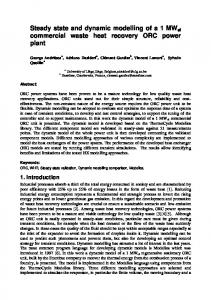
3.3. Thermodynamic simulations The simulations have been performed by varying the cycle top pressure over a wide range, both for what concern Rankine and ORC, specifically in the range 6-34 bar for the ORC and 3-25 bar and 5-40 bar respectively for the ship and yacht one Rankine cycle respectively. A minimum ΔT of 20 K has been imposed for all heat exchangers in order to obtain reasonable values for the heat transfer surfaces. As Figure 5 shows, the Rankine cycle top temperature has been kept constant at a value 20 K lower than the ICE exhaust gas while the ORC one varies depending on the Rankine cycle top pressure. Both the Rankine and ORC turbine outlet pressures have been maintained as small as possible, considering the restriction of at least 20 K difference between the condensing stream and the cooling water (298 K). The Rankine outlet pressure has been therefore fixed at 0.13 bar in both cases and the ORC outlet pressures at 3 bar and 4.5 bar respectively for the R245fa and R600 respectively.
Figure 5: T-s diagram of the simulated Rankine and ORC integrated recovery systems
4. Critical analysis of the results The selected system layout depends on the size of the ICE. For the ship (3x12.6 MW, turbocharged) the choice was to consider the RbORC configuration only, with the addition of a low pressure ORC fed by the HT cooling water. This choice is dictated by taking into consideration the physical dimensions of the vessel components, which suggest not to select complex plant schemes. The yacht plant, instead, has been simulated using each of the presented configurations. The following table details the mass flow rates evolving into the cycles, providing a first indication of the system size. Table 3: Mass flow rates ranges in the simulated cyles
Water mass flow rate range [kg/s] R 245fa mass flow rate range [kg/s] R 600 mass flow rate range [kg/s]
YACHT 0.022 - 0.025 0.05 – 0.07 0.026 – 0.039
7
VESSEL 0.8 – 1.52 10 - 11 6-7
PROCEEDINGS OF ECOS 2015 - THE 28TH INTERNATIONAL CONFERENCE ON EFFICIENCY, COST, OPTIMIZATION, SIMULATION AND ENVIRONMENTAL IMPACT OF ENERGY SYSTEMS JUNE 30-JULY 3, 2015, PAU, FRANCE
The results presented in Figure 5 show the plant power output, the exhaust gas temperature and the first law efficiency of the selected configurations. The Rankine cycle has been analyzed first. Figures 6a and 6c show the cycle efficiency and the power output while figures 6b and 6d display the increment of those values with respect to the non-recovered ICE. a)
c)
b)
d)
Figure 6: Rankine cycle power output and efficiency values (a,c) and percentual increment over the ICE (b,d) for yacht and vessel
For the yacht, the power output shows a maximum for a Rankine top pressure of 35 bar (17.16 kW), decreasing for higher top pressure values (Figure 6a). The reason is that the mass flow rate the exhaust gas is able to heat up decreases for higher pressures because of the pinch point limitation, resulting in a higher final exhaust gas temperature. The ship power output (Figure 6c), instead, reaches a maximum for Rankine cycle top pressure of 5 bar (706 kW). The exhaust gas temperature being lower than the that of the yacht makes it inconvenient to raise the cycle top pressure above this limit. Figures 6b and 6d show how the efficiency and power output can be increased using the WHR system, with respect to the ICE, of 2.11%, 2.67% and 9.32%, 8.11% respectively for the vessel and the boat. The higher percentage values obtained for the yacht depend on the higher exhaust gas temperature, due to the atmoshperic intake ICE; in addition, as previously mentioned, half of the ship exhausts are already used to pre-heat the fuel. Due to the similar trends of ship and yacht performance, hereinafter only the results of the yacht will be reported; a comprehensive analysis of simulation results is discussed in [19]. Figure 7 represents the simulation results of the Rankine/ORC configurations, to identify the improvements the dual loop cycle brings to the complete energy system. Figures 7a, 7b and 7c report the 1st law efficiency percentage increase for three different dual loop WHR 8
PROCEEDINGS OF ECOS 2015 - THE 28TH INTERNATIONAL CONFERENCE ON EFFICIENCY, COST, OPTIMIZATION, SIMULATION AND ENVIRONMENTAL IMPACT OF ENERGY SYSTEMS JUNE 30-JULY 3, 2015, PAU, FRANCE
system configurations (compared to the non-recovered ICE), using R245fa as the ORC working fluid. The same graphs have been obtained for the R600. The maximum value obtained displays an increase of 9.86% considering 40 bar for the Rankine top cycle pressure and 16 bar for the ORC’s. Figure 7d reports the system power output related to every plant scheme analyzed, and it indicates that it reaches a maximum of 18.38 kW with a 40 bar Rankine top pressure and a 18 bar R245fa for the ORC. The same behavior is observed for the large vessel in which the maximum efficiency raise is 2.96 % and the maximum power output 897.4 kW choosing for the Rankine cycle and ORC top pressures of 25 bar and 34 bar (R245fa) respectively. a)
c)
b)
d)
Figure 7: Efficiency increment for the yacht Rankine/ORC scheme analyzed (a,b,c) and WHR power output (b) for the Rankine/ORC plant scheme
The outlet gas temperature decreases with the ORC top pressure because of the pinch point limitation. the minimum allowable value being 70 °C both for the ship and the yacht, considering the lowest simulated ORC top pressure (6 bar). Figure 8 shows the curves referred to the yacht application with a 10 bar Rankine top pressure. An exhaust gas temperature as low as 70 °C could be reached just in case a sulphur free fuel is selected for the propulsion system. For what concern the specific application, the italian shipiard company is already considering the use of the LNG to propel its ships.
9
PROCEEDINGS OF ECOS 2015 - THE 28TH INTERNATIONAL CONFERENCE ON EFFICIENCY, COST, OPTIMIZATION, SIMULATION AND ENVIRONMENTAL IMPACT OF ENERGY SYSTEMS JUNE 30-JULY 3, 2015, PAU, FRANCE
Figure 8: Outlet gas temperature for the Rankine/ORC plant scheme
Regeneration has been also analyzed in this work for the yacht, showing that the efficiency increases at a higher rate than the Rankine cycle top pressure (Figure 9). The maximum value calculated refers to the R600 ORC cutoff top pressure when the Rankine cycle top pressure is kept at 40 bar (0.073).
Figure 9: ORC efficiency increase using regeneration
The results obtained by the process simulations allow to perform a preliminary design of the WHR system. The yacht WHR system components size has been estimated in order to figure out the needed storage volume. The heat transfer surface has been calculated using the NTU method [11], convenient in presence of fluid vaporization. The selected heat transfer coefficient value is 500 W/m2K and the casing size has been considered as well. Table 4 presents the values for the Rankine cycle configuration. Table 4: Yacht Rankine cycle components size HRSG [cm]
R=8 cm L=143 cm
Turbine [cm]
37x26x26
Condenser [cm]
70x70x80
Pump [cm]
22x11x10
Notice that for the HRSG a helicoidal heat exchanger is suggested, with R and L respectively the radius and length of the helicoid. The component volume allows for an easy deployment in the technical area of the boat. 10
PROCEEDINGS OF ECOS 2015 - THE 28TH INTERNATIONAL CONFERENCE ON EFFICIENCY, COST, OPTIMIZATION, SIMULATION AND ENVIRONMENTAL IMPACT OF ENERGY SYSTEMS JUNE 30-JULY 3, 2015, PAU, FRANCE
The monetary savings brought about by the recovery system have been calculated as a percentage of the actual fuel costs when the boat runs at steady state, as selected for the simulations. It has been assumed that the recovered electric power, in absence of the WHR system, should be produce by the ICE using additional fuel. Therefore, considering the actual fuel cost, the calculated savings are 6.19 €/hour and 84 €/hour respectively for the boat and the ship, which means percent savings of 8-7 % and 3.4 % respectively. For what concern the vessel, the yearly monetary savings have been estimated at 350000 €, considering the actual ship operating schedule (approximately 12 hours/day) and the current fuel price.
5. Conclusions In this study, several marine waste heat recovery system configurations for two different values of the installed ICE power have been analyzed, in order to evaluate the potential of the repowering both in terms of energy production and environment reliability. For the yacht, the results of the simulations demonstrate that -as expected- the addition of a bottoming ORC to the Rankine cycle brings advantages in terms of efficiency, power output and exhaust gas temperature. Our calculations show how regeneration is a convenient method for improving the ORC efficiency, at least when recovering heat from a low temperature source: it does though not bring advantages in terms of power output for the waste heat recovery systems analyzed at steady state. Two organic working fluids were compared, and R245fa was found to offer thermodynamic advantages over R600, since it allows for a lower condensation pressure, that increases both cycle efficiency and power output. On the other hand, R600 allows to reach lower gas outlet temperatures, which implies a more extensive use of the available waste heat. The preliminary design proposed for the yacht WHR system allows to state that the plant is small enough to be installed inside the engine case. Nomenclature Acronyms HRSG HT ICE LMTD LT ORC RbORC RbORCr RbORCri WHR
Heat Recovery Steam Generator High Temperature Internal Combustion Engine Logarithmic Mean Temperature Difference Low Temperature Organic Rankine Cycle Rankine bottoming Organic Rankine cycle Rankine bottoming Organic Rankine cycle regenerated Rankine bottoming Organic Rankine cycle regenerated and integrated Waste heat recovery
11
PROCEEDINGS OF ECOS 2015 - THE 28TH INTERNATIONAL CONFERENCE ON EFFICIENCY, COST, OPTIMIZATION, SIMULATION AND ENVIRONMENTAL IMPACT OF ENERGY SYSTEMS JUNE 30-JULY 3, 2015, PAU, FRANCE
Symbols h LHV m p P Qlost sfc T U ηI ρ Subscripts c c1 c2 ECO h h1 h2 In L Out p SH T V VAP w
Specific enthalpy Lower heating value Mass flow rate Pressure Power Heat loss Specific fuel consumption Temperature Heat transfer coefficient 1st law efficiency Density
[kJ/kg] [kJ/kg] [kg/s] [bar] [kW] [kW] [kg/h] [K] [kW/m2K] [-] [kg/m3]
Cold Cooling fluid when working fluid is at saturated liquid state Cooling fluid when working fluid is at saturated vapor state Economization Hot Hot fluid when working fluid is at saturated vapor state Hot fluid when working fluid is at saturated liquid state Inlet Liquid Outlet Pump Super-heating Turbine Vapor Vaporization water
References [1] Amati V., Coccia A., Sciubba E., Toro C., Camel Pro Users’ Guide, 2008, http://www.turbomachinery.it [2] Bao J., Zhao L., A review of working fluid and expander selections for Organic Rankine cycle, Ren. Sust. Energy Reviews, 24: 325-342, 2013 [3] Centro Internazionale di Ricerca & Calcolo Universitario Scientifico (CIRCUS), http://www.turbomachinery.it/ [4] Chen H., Goswami D.Y., Stefanakos E.K., A review of thermodynamic cycles and working fluids for the conversion low-grade heat, Ren. Sust. Energy Reviews , 14: 3059-3067, 2010 12
PROCEEDINGS OF ECOS 2015 - THE 28TH INTERNATIONAL CONFERENCE ON EFFICIENCY, COST, OPTIMIZATION, SIMULATION AND ENVIRONMENTAL IMPACT OF ENERGY SYSTEMS JUNE 30-JULY 3, 2015, PAU, FRANCE
[5] Clemente s., Micheli D., Reini M., Taccani R., Bottoming organic Rankine cycle for a small scale gas turbine: A comparison of different solutions, Applied Energy, 106: 355-364, 2013 [6] Colonna P,, van der Stelt T.P. , FluidProp: aprogram for the estimation of thermo physicalproperties of fluids, Energy Technology Section, Delft University of Technology, TheNetherlands, 2004, http://www.FluidProp.com [7] El Chammas R., Clodic D., Combined Cycle for Hybrid Vehicles. Society of Automotive Engineers (SAE), 2005 [8] Hossain S.N., Bari S., Waste heat recovery from the exhaust of a diesel generator using Rankine cycle, Energy Conv. and Management, 75: 141-151, 2013 [9] Hung T.C., Wang S.K., Kuo C.H., Pei B.S., Tsai K.F., A study of organic working fluids on system efficiency of an ORC using low-grade energy resources, Energy, 35(3): 1403-11, 2010 [10] Morton, A.J., Thermodynamics of Waste Heat Recovery in Motor Ships, Trans. Inst. of Marine Engineers, Conf. on Organic Fluids for Waste Heat Recovery in Ships and Industry, pp. 1-7, January 7-8, 1981 [11] Nellis G., Klein S., Heat transfer, Cambridge University press, 2008 [12] Quoilin S., Declaye S., Tchanche B.F., Lemort V., Thermo-economic optimization of waste heat recovery Organic Rankine Cycles, Appl. Thermal Eng. 31: 2885-2893, 2011 [13] Saleh B., Koglbauer G., Wendland M. Fischer J., Working fluids for lowtemperature Organic Rankine Cycles, Energy, 32: 1210-1221, 2007 [14] Sciubba E., A critical interpretation and quantitative extension of the SamaSzargut Second Law rules in an extended exergy perspective, Energies, 7: 53575373, 2014 [15] Shahinfard S., Beyene A., Regression comparison of organic working mediums for low grade heat recovery operating on Rankine cycle, Journal of power technologies, 93:257-270, 2013 [16] Stijepovic M.Z., Linke P., Papadopoulos A., Grujic A.S., On the role of working fluid properties in organic Rankine cycle performance, Appl. Thermal Eng., 36: 406-13, 2012 [17] Tchanche B. F., Lambrinos Gr., Frangoudakis A., Papadakis G., Low grade heat conversion into power using organic Rankine cycles- A review of various applications, Ren. Sust. Energy Reviews, 15: 3963-3979, 2011 [18] Tian H., Shu G., Wei H., Liang X., Liu L., Fluids and parameters optimization for the organic Rankine cycle (ORCs) used in exhaust heat recovery of internal Combustion Engine (ICE), Energy, 47: 125-136, 2012 [19] Tocci L., Modelling and simulation of waste heat recovery systems for marine applications, M. Eng. Thesis Mechanical Engineering, U. of Roma Sapienza, 2014 [20] Vankeirsbilck I., Vanslambrouck B., Gusev S., Energetical, Technical and Economical considerations by choosing between a Steam and an Organic Rankine Cycle for Small Scale Power Generation, Proc. ORC 2011: First International Seminar on ORC Power Systems, Delft, The Netherlands, September 2011
13
PROCEEDINGS OF ECOS 2015 - THE 28TH INTERNATIONAL CONFERENCE ON EFFICIENCY, COST, OPTIMIZATION, SIMULATION AND ENVIRONMENTAL IMPACT OF ENERGY SYSTEMS JUNE 30-JULY 3, 2015, PAU, FRANCE
[21] Yu G., Shu G.,Tian H., Wei H.,Liu L., Simulation and thermodynamic analysis of a bottoming Organic Rankine Cycle (ORC) of diesel engine (DE), Energy, 51: 281-290, 2013 [22] Zheng H. G., Wang E. H., Fan B. Y., A performance analysis of a novel system of a dual loop bottoming organic Rankine cycle (ORC) with a light-duty diesel engine, Applied Energy, 102: 1504-1513, 2013 [23] Zheng Z., Tang X., Asa-Awuku A., Jung H.S., Characterization of a method for aerosol generation from heavy fuel oil (HFO) as an alternative to emissions from ship diesel engines, J. Aerosol Science, 41: 1143-1151,2010
14