Thermodynamic and technical criteria for the optimal selection of the working fluid in a miniORC Benjamin Franchettia, Apostolos Pesiridisb, Ioannis Pesmazoglouc, Enrico Sciubbad, Lorenzo Toccie,f a
Entropea Labs, 2aGreenwood Road, E81AB, London, UK,
[email protected] Department of Mechanical, Aerospace anc Civil Engineering,, Center of Advanced Powertrain and Fuels (CAPF), Brunel University, London, UK,
[email protected] c Entropea Labs, 2aGreenwood Road, E81AB, London, UK,
[email protected] d Department of Mechanical and Aerospace Engineering,, University of Rome “Sapienza”, Italy,
[email protected] e Department of Mechanical and Aerospace Engineering,, University of Rome “Sapienza”, Italy,
[email protected] (CA) f Entropea Labs, 2aGreenwood Road, E81AB, London, UK,
[email protected]
b
Abstract: Waste energy recovery (WER) is a suitable solution to improve the fuel utilization of Internal Combustion Engines (ICEs) by producing an eco-friendly electrical power from an energy source currently wasted. Organic Rankine Cycle (ORC) technology has been developed in the past few years to generate electric power from medium temperature (500 K – 800 K) ICE wasted thermal sources. Working fluid selection represents the first step in the design of an ORC. At the state of the art, authors where not able to select a single optimal organic fluid. This is mainly because of the different thermodynamic conditions of the heat sources which offer wasted thermal energy. This paper proposes a procedure for the ORC system preliminary working fluid selection, which takes into consideration thermodynamics and design parameters of the system components. The study is applied to WER systems specifically designed as bottoming cycles to ICE for transport applications. However, the method is quite general and makes the model easily adaptable to different heat sources. A steady state thermodynamic model of the system is developed via the software MATLAB. A wide variety of organic fluids (OF), such as R245fa, Solkatherm (SES36) and hexane have been investigated to identify the candidate which offers the best recovery opportunity. Regeneration is also included in this work. Results show that recover thermal energy in the regenerator is an essential method to improve power recovery when applying ORC to WER systems. The effect of superheating on the system power output has been investigated as well. It is capable to increase the cycle power output only when coupled with regeneration. The paper shows that the addition of a bottoming ORC to the ICE is convenient both in terms of recovered electric power (up to 14% of the engine nameplate power) and heat source utilization rate (up to 11 % heat source conversion into electricity). In addition, it is shown that water offers lower performance with respect to organic fluids when considering single stage radial expanders.
Keywords: Waste Energy Recovery, ORC, optimal fluid selection, organic fluid.
1. Introduction Waste energy recovery based on Organic Rankine Cycles is widely considered the most interesting technology to improve thermal energy systems efficiency and pollutant emissions. A literature survey [1-3], shows that the optimal selection of the working fluid is a multi-parametric problem. Therefore, the optimal fluid selection depends on the parameters considered as “relevant”. The increasing availability of a large number of chemical compounds, together with the wide spectrum of the thermodynamic conditions of the different possible waste energy sources, complicates the choice. Most of the studies screen fluids based only on their thermodynamic properties; Liu [4] analyzed several working fluids in terms of thermal efficiency and total heat recovery efficiency, Hung [5, 6] 1
indicates R 113 and R 123 to have the best performance based on a thermodynamic analysis that covers different fluids such as benzene, p-xylene, ammonia, toluene, R11 and R12. Yu and Shu [7] studied a bottoming ORC applied to a 300 hp ICE, considering both exhaust gas and jacket water as heat sources; their results show an increase in thermal efficiency up to 6.1 % and a recovered electric power of 15.5 kW. According to Quoilin [8], there are mainly two reasons why these studies reach contrasting conclusions in terms of optimal working fluid selection: on one hand, the set of investigated parameters differs from one analysis to the other; on the other hand, the specific applications taken into consideration also display substantial differences. A few authors stress the need to couple the working fluid selection with the design of the expander; in fact, the selection of a dynamic or volumetric expander introduces constraints on the thermodynamic parameters selection. Lazzaretto [9] proposes an ORC optimization based on the use of efficiency correlations for what concerns the turbine, either of radial or axial type. Quoilin [10] selects the ORC working fluid based on the expander operating maps. Different papers deal with the design of ORC dynamic expanders. The fluid under analysis is commonly chosen through a purely thermodynamic analysis. Costall [11] proposes different radial expander geometries comparing Toluene and MDM as working fluids; Fiaschi [12] focuses on expander losses related to the thermodynamic properties of the working fluid investigated. Heat exchangers design takes a crucial role in the definition of the size of the ORC. Alaez [13] investigates over the use of plastic heat exchangers for ORC applications, considering n-heptane selected from a previous thermodynamic analysis. Xu [14] uses R 134a to compare shell and tube and plate heat exchangers neglecting an optimal fluid selection. The objective of this paper is to define a method to predict the challenges faced in the components design when selecting the working fluid and defining its cycle thermodynamic parameters. Among the different WHR applications, ORCs bottoming Diesel ICEs offer the potential to reach high power recovery rates, because of the high exhaust gas temperatures (600 K – 800 K) [15-17]. Many authors highlight the potential of such applications: Bianchi [13] underlines the promising performance of ORC in the exploitation of medium temperature heat sources such as the ICE exhaust gas, while Tian [18] claims it is possible to reach up to 16 % cycle efficiency using R141b as an operating fluid in WHR system for engine applications. This work proposes a novel method for the selection of the proper working fluid for ORC-WER systems based on a radial expander in which thermodynamic properties and evaporator heat transfer surface are taken into account. The study is applied to the selection of the working fluid for the recovery of waste heat deriving from an automotive truck 250 hp Diesel ICE. The paper includes the MATLAB code developed for the selection and illustrates in detail the different steps taken in the fluid selection procedure. A critical analysis of the results and conclusions is presented as well.
2
2. ORC plant scheme
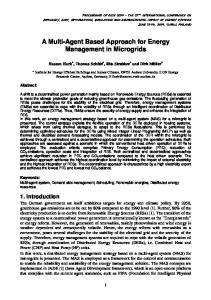
Figure 1 ORC thermodynamic points
Figure 1 shows an ORC process for a general organic fluid. The cycle involves a number of transformations that introduce state and phase changes to the working fluid: 1. 1 2 A pump increases the fluid pressure from cycle bottom to top; 2. 2 3 The working fluid is heated to its liquid saturation state (point 3) in the pre-heater; 3. 3 4 The working fluid is vaporized in the boiler in order to reach the vapor saturation curve; 4. 4 5 The fluid is superheated in the super-heater; 5. 5 6 The working fluid is expanded in a turbine to produce the required extra output; 6. 6 1 The fluid is brought back to its initial thermodynamic conditions via a condensation process. Notice that in Figure 1 the sub-steps marked 9 and 10 are included. The working fluid exiting the turbine is cooled from 6 9, releasing an amount of thermal energy which is used to pre-heat the fluid at the pump outlet (2 10). This process, known as regeneration, is also included in this work, to evaluate the possible improvements it may lead to. The components included in an ORC are: 1. Pump 2. Evaporator 3. Turbine 4. Condenser 5. Regenerator (if present) The most relevant parameters in the design of an ORC thermodynamic cycle are[8, 10]: 1. 𝛽: the turbine expansion ratio; 2. The cycle bottom (minimum) pressure, which defines -in conjunction with β- the cycle top (max) pressure; 3. 𝛥𝑇𝑠ℎ : the degree of super-heating (𝑇5 − 𝑇4 , see Figure 1); 4. The presence or absence of the regeneration process (69 and 210); 3
5.
The working fluid mass flow rate.
The aforementioned properties are set as the free variables for the analysis. Notice that all of the parameters vary within a range that depends on the physical and chemical properties of the organic fluid under consideration. Table 1 Design parameters held fixed in the sensitivity analysis
Fixed parameters 𝛥T sub-cooling [K] Turbine efficiency Pump efficiency Cooling water temperature [K] Cooling water mass flow rate [kg/s] Pinch point condenser [K] Pinch point evaporator Heat transfer coefficient [W/m2K] Exhaust gas mass flow rate [kg/s] Exhaust gas temperature [K] Exhaust gas pressure [bar] Exhaust gas outlet temperature limit [K]
Value 5 0.8 0.8 303.15 2 10 10 600 0.3 753.15 1 363.15
Table 1 reports the fixed parameters of the cycle. Among the others, Table 1 displays the pinch points for both the evaporator and the condenser. The choice of this value has been selected to reach a good balance between heat exchanger exergy losses and heat transfer surface. An additional restriction is that the exhaust gases temperature at which the gas leaves the WER system should not be lower than 90 C in order to avoid acid condensation in the exhaust manifold. Notice that the efficiencies of the expander and of the pump are constant throughout the calculations. The heat transfer coefficients in all evaporator sections are considered constant and equal. Constant values are sufficient in the context of the present fluid-selection study. Once the working fluid is chosen, a second-level analysis needs to be performed at the final design stage.
3. Cycle modelling using Matlab The model developed using the MATLAB code is presented in the following paragraph. The thermodynamic analysis proceeds by calculating the cycle properties at each of the points (numbered 1 through 6 in Figure 1) of the ORC. To this end, the mass and energy balance equations are used for each point.
3.1. ORC Thermodynamic model 3.1.1 - PUMP The pump is assumed to be electrically powered; in the absence of leakages and for adiabatic operation, mass and energy balance are: 𝑚𝑤𝑓,1 = 𝑚𝑤𝑓,2 𝑃𝑝𝑢𝑚𝑝 =
(1)
𝑚𝑤𝑓,1 ∗(ℎ2,𝑖𝑠 − ℎ1 )
(2)
𝜂𝑝𝑢𝑚𝑝 𝜂𝑚𝑜𝑡𝑜𝑟
4
3.1.2 – EVAPORATOR In a Rankine cycle applied to WER, thermal energy is provided to the working fluid by the hot exhaust gases. In order to be able to control the pinch point temperature difference, the evaporator energy balance is split in 3 transformations; namely: pre-heating, vaporization and super-heating. 𝑚ℎ𝑠,1 = 𝑚ℎ𝑠,4 𝑚𝑤𝑓,10 = 𝑚𝑤𝑓,5
(3) (4)
𝑚ℎ𝑠,1 ∗ (ℎℎ𝑠,1 − ℎℎ𝑠,4 ) = 𝑚𝑤𝑓,10 ∗ (ℎ5 − ℎ10 )
(5)
Equation (5) expresses the total energy balance of the evaporator. 3.1.3 - STEAM TURBINE The mass balance of the turbine is given by (1), while the output-power is expressed as: 𝑃𝑡𝑢𝑟𝑏𝑖𝑛𝑒 = 𝜂𝑡𝑢𝑟𝑏𝑖𝑛𝑒 ∗ 𝑚𝑤𝑓,1 ∗ (ℎ5 − ℎ6,𝑖𝑠 )
(6)
3.1.4 - CONDENSER As mentioned, the energy balance of each component allows to control the pinch point temperature. The mass balance is expressed by equation (4). 𝑚𝑤𝑓,6 ∗ (ℎ6 − ℎ1 ) = 𝑚𝑐𝑓,1 ∗ (ℎ𝑐𝑓,4 − ℎ𝑐𝑓,1 )
(7)
Equation (7) expresses the energy balance for the condenser. 3.1.5 - REGENERATOR The regenerator is modeled considering the total energy balance. Notice that, since none of the fluid changes phase in the process, the lowest 𝛥𝑇 appears either at the component inlet or outlet; for this reason, there is no need for a pinch point check. The mass balance of the heat exchanger is expressed by equation (4) while the energy balance is: 𝑚𝑤𝑓,5 ∗ (ℎ6 − ℎ9 ) = 𝑚𝑤𝑓,𝑖𝑛,1 ∗ (ℎ10 − ℎ2 )
(8)
Where 𝑚𝑤𝑓,5 and 𝑚𝑤𝑓,1 refer respectively to the working fluid mass flow rate leaving the turbine and the one pressurized by the pump. Notice that pressure losses in heat exchangers are neglected in this study.
3.2. Turbine design parameters In addition to the thermodynamic analysis, the code is capable of identifying a preliminary turbine design, which is useful to roughly determine the size of the expander and its operating rotational speed. The preliminary expander design is based on the usual non-dimensional similarity parameters, the specific diameter (𝑑𝑠 ) and the specific rotational speed (𝑛𝑠 ) [19], described by the equations: 𝑑𝑠 =
𝐷∗ 𝑊 1/4
(9)
√𝑄
5
𝑛𝑠 =
𝜔∗ √𝑄
(10)
𝑊 3/4
Where 𝝎 is the rotational speed, 𝐷 is the rotor maximum diameter, 𝑊 is the specific work and 𝑄 is the volumetric flow rate of the working fluid at the turbine inlet. Equations (9) and (10) were used in conjunction with the Balje chart [19] to map the optimal external diameter 𝑑𝑠 and rotational speed 𝑛𝑠 for a given volumetric flow rate of the working fluid 𝑄 and the specific work 𝑊. The values of 𝑄 and 𝑊 were retrieved from the thermodynamic energy-balance analysis. The values selected for the 𝑛𝑠 and 𝑑𝑠 parameters are the optimal ones for radial turbines, respectively 0.55 and 4 according to Balje [19]. Turbine inlet diameter and rotational speed are calculated using equations (9) and (10). By coupling the thermodynamic analysis with the geometrical constraints of the turbine design, the feasibility of each solution can be properly evaluated.
3.3. Mathematical model Based on the cycle description provided in paragraph 3.1 and 3.2, the MATLAB code calculates the maximum mass flow rate of the working fluid that the heat source is able to vaporize. According to this value, the cycle’s thermodynamic points are calculated. Notice that the mass flow rate is calculated taking into account the limits imposed by the pinch point and the minimum exhaust gas temperature at the ORC outlet. In the process, the mass flow rate of the OF is maximized to obtain the maximum turbine power-output. When the numerical process converges, the turbine’s rotational speed and external diameter are calculated using the non-dimensional parameters 𝑛𝑠 and 𝑑𝑠 (equations (9) and (10) or their equivalents). It is needed to point out that pressure losses during heat transfer phases are neglected in this work. Pressure losses effect might lead to non-feasible plant size for certain organic fluids. Therefore future works from these authors will take this parameter into account. A maximum expansion ratio 𝛽is imposed for each fluid by two requirements: to design a single stage radial turbine and to limit the maximum inlet peripheral velocity of the turbine to 400 m/s.
4. Working fluid selection procedure Section 4 provides an overview of the steps considered to select the proper working fluid for the specific WER-ORC application.
4.1. Fluid selection The first step in the selection of the possible working fluids consists of the investigation of different fluid categories presented in the literature and in existing ORC applications. This narrows down the OF options. Among the hundreds of fluids available, it is necessary to select either non-flammable fluids or flammable fluids whose auto-ignition temperature is significantly higher than that of the exhaust gasses leaving the ICE. For example, only a small subset of the Alkanes can be considered, namely those with a flammability limit that is at least 50 °C higher than the heat source of the ORC under study. Note that another major consideration in the selection of appropriate organic fluids is the temperature at which they deteriorate/decompose. A deteriorated OF has poor thermodynamic and heat transfer properties. If either the deterioration limit or flammability limit is reached for a certain candidate OF, 6
then the only way to circumvent the problem is to consider a secondary thermal loop wherein a thermal oil is used to extract the heat from the exhaust gas. By varying the mass flow rate of the thermal oil, one may regulate its bulk average temperature. The thermal oil is then used for the evaporation of the organic fluid with a secondary heat exchanger (as opposed to directly exchanging heat between the exhaust gasses and the OF). This way the OF is exposed to a lower maximum temperature and deterioration/ignition is avoided, but of course at the cost of technical complications and economic penalties. It must be remarked that the temperatures of the OF and of the heat source are average values. Therefore, in order to prevent fluid deterioration, the selected OF must have a flammability/deterioration limit well above the heat source temperature. For the purpose of this analysis, fluids with lower flammability and deterioration temperatures than that of the heat source are though also considered. The purpose of including such fluids is to evaluate whether they can achieve a substantially higher power output than OFs with higher flammability and deterioration temperatures. Such fluids involve the additional cost of a more complex system. The fluids listed in Table 2 are the ones investigated in the following analysis and are also the ones most commonly used in the literature and in real ORC applications [8, 9, 15]. Table 2 Organic fluids selected for the analysis
Organic fluid Benzene R245fa Toluene Butene p-Xylene o-Xylene n-butane (R600) MD3M Cyclopentane Decane Heptane Pentane (R601) ISO-butane (R600a) R236ea Cyclohexane Hexane SES 36
Critical temperature, K 562 427.01 591.80 418.09 616.23 630.33 407.818 629 511.7 617.7 540.2 469.8 407.817 412.44 554 507.6 450.7
Critical pressure, bar 48.9 36.51 41.09 40.098 35.11 37.32 36.29 9.45 45.1 21.1 27.36 33.6 36.29 37.03 40.7 30.2 28.49
Molar mass, kg/kmol 78.11 134.048 92.14 56.1 106.16 106.16 58.12 384.8 70.13 142.28 100.2 72.15 58.12 152.04 84.16 86.17 184.85
The fluids in bold in Table 2 are the most frequently employed in current applications [8]. The analysis will proceed with a screening of the working fluids based on several design tasks. The goal is to end up with a few fluids and equivalent ORC configurations, which will be subsequently studied in greater depth. Finally, in addition to the discussed fluids, water is also included in this work for the purpose of comparison and to evaluate the option of using a steam Rankine cycle.
7
4.2 Organic fluid cycle power output comparison Following the preliminary elimination of OF options, an ad hoc MATLAB code was used to further narrow down the feasible ORC working fluids and configurations. The net turbine power output was taken as the objective function. A preliminary inspection of the variables under investigation led to the following considerations: - The 𝛥Tsh is usually absent in an ORC as it is not essential to guarantee the absence of liquid drops at turbine outlet. - The minimum pbottom,cycle is constrained by the corresponding saturation temperature of the OF. This saturation temperature needs to be higher than the temperature of the cooling fluid (here a temperature of 303.15 K is considered for the cooling fluid). The maximum 𝑝𝑏𝑜𝑡𝑡𝑜𝑚,𝑐𝑦𝑐𝑙𝑒 is constrained both by 𝛽and by the critical point of the equivalent fluid’s T-s diagram (since for a given 𝛽 the top pressure is 𝛽 ∗ 𝑝𝑏𝑜𝑡𝑡𝑜𝑚,𝑐𝑦𝑐𝑙𝑒 < 𝑃𝑐𝑟𝑖𝑡𝑖𝑐𝑎𝑙 ).
Figure 2 Cycle power output as a function of β and 𝛥Tsh
Figure 2 shows the variation of cycle power output with cycle bottom pressure for different pressure ratios and degrees of superheating (𝛥𝑇𝑠ℎ ) for Benzene as the working fluid. 1 The set of lines at the top of the diagram are representative of an ORC with regeneration, whereas those at the bottom are for an ORC without regeneration. One of the findings of this preliminary study was that for all fluids considered the regeneration is beneficial both in terms of system efficiency and turbine power output, for the specific heat source conditions assumed in this work. For this reason it was concluded that regeneration must be included in the ORC. In fact, regeneration increases the amount of working fluid mass flow rate the heat source is able to vaporize. This is for 2 combined effect. On one hand, the specific thermal energy release to the condenser is lower when regenerated ORC is considered (represented by the area underneath transformation 91 instead of 61 for non-regenerated ORC, Figure 1). On the other hand, the regenerated specific heat needs to be added to the heat the working fluid gains from the heat source. This leads to an increase of the overall thermal power transferred to the organic fluid, leading to an increase of the OF mass flow rate at given thermodynamic conditions. Another important conclusion of the study deals with the concept of super-heating. For any given fluid tested, it is observed that super-heating is not beneficial in terms of power output when regeneration is not included. Instead, regeneration coupled with super-heating generally leads to an increase of the turbine power output, as shown in Figure 2.
1
Note that the power output is shown here as an example of the data provided by the analysis. The same analysis was implemented for all of the considered OFs and equivalent results were obtained
8
Table 3 Power output for the ORC included in Table 2
Organic fluid Cyclopentane Cyclohexane Pentane (R601) Hexane Toluene SES36 Benzene Heptane Butene
Max power output, kW 24.99 24.93 24.48 24.33 24.24 23.66 23.56 23.15 22.83
Organic fluid R 245fa n-butane (R600) Isobutane (R600a) p-Xylene o-Xylene Decane R236ea MD3M Water
Max power output, kW 22.15 21.99 21.38 20.52 20.05 18.25 14.19 9.77 5.5
Table 3 reports the results in terms of power output for each organic fluid considered in the analysis. The underlined fluids are phased out from the selection process, since they offer a lower power output with respect of the other OF taken into account. The analysis shows that only Toluene, Benzene and SES36 could be employed without the need for a primary thermal oil circuit, because of their high auto-ignition temperature. The performed analysis provides some interesting results about the OF behavior: - The optimal super-heating rate 𝛥𝑇𝑠ℎ depends on the selected organic fluid; for example, from Figure 2 it is seen that the ORC with regeneration generates a comparable power if the superheating is added. In other cases, such as Cyclopentane, the super-heating limit is imposed by decomposition and flammability limits. Therefore, the optimal level of superheating is both cycle- and fluid-specific. - In all fluids considered the turbine pressure ratio 𝛽 results in higher power outputs. The upper limit of the turbine pressure ratio 𝛽 is limited by the turbine inlet peripheral velocity. However, the system power output could be further increased by adopting a multi-stage expander (at the expense of a higher system-cost). - The maximum power output is constrained by at least one of the variable parameters. In the case of Toluene, for instance, it is limited by the maximum turbine peripheral velocity and by the decision to consider a single stage radial expander; for SES 36, instead, the limit is the maximum 𝛽, therefore a super-critical cycle configuration should be adopted to increase the output. - The organic fluid volumetric flow rate has a crucial influence on the turbine efficiency; in fact, since these 2 parameters are roughly proportional, it is preferable to select a low density fluid. However, this choice would lead to an increase in the heat exchanger size. For the sake of completeness, the choice of water as working fluid was also considered. The choice of a single stage radial turbine leads to a low 𝛽 value, directly proportional to the power output. The addition of a multi-stage turbine would increase the power output, at the cost of a reduced costeffectiveness of the ORC plant.
4.3 Components behavior comparison The final thermodynamically-driven evaluation of OF options is based on the effect of the OF on the required components of the ORC, namely:
9
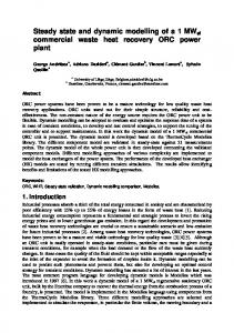
The evaporator heat transfer surface2 needs to be minimized due to the space constraints, since this component has to be fitted into the immediate surroundings of the ICE exhaust manifold. In addition, heat transfer surface is proportional to the engine backpressure for a given cross sectional area of the heat exchanger; - The Radial turbine rotational speed3 is known to affect the turbine efficiency (furthermore, excessive rotational speeds lead to manufacturing and operational problems). The expander/turbine is directly coupled to the Power Conversion Unit (PCU), which performs the mechanical-electrical power conversion, and the alternator would become much more expensive should its rotational speed exceed 70000 rpm; - The Back work ratio (BWR), i.e., the ratio between pump and turbine power, must be minimized to maximize the cycle net power output; - The Turbine external diameter should fall within the dimensional constraints of the retrofitting capability of the technology. Evaporator size and turbine rotational speed are shown in Figure 3 to compare the different fluids left in the analysis. From accurate analysis, these two variables change over a wider range among the aforementioned ones, depending on the OF selected. The thermodynamic parameters taken into consideration in Figure 3 refer to the degree of superheating and pressure ratio which offer top performance in terms of turbine power output, according to the results obtained in section 4.2. Regeneration is included in all cycles, since paragraphs 4.2 shows it increases both power output and cycle efficiency. -
a
b Figure 3 Evaporator and turbine parameters referred to different organic fluids
Figure 3a and Figure 3b show the rotational speed of the turbine and the evaporator’s heat transfer surface for the different organic fluids considered. At this stage, Cyclopentane, Pentane and Butene are pruned from the list of candidates because they result in a turbine rotational speed in excess of the feasible limit (> 70000 rpm). Decreasing the rotational speed for these fluids leads to selecting suboptimal 𝑛𝑠 and 𝑑𝑠 and to a lower turbine isentropic efficiency. The density of the organic fluids4 strongly affects the design of both the heat exchangers and turbine. A low density implies high volumetric flow rate for a given mass flow rate. A low 𝑄 is beneficial in the design of the heat exchangers because -for comparable 𝑅𝑒- it decreases the pressure losses therein and allows for a smaller pipe diameter for a given pumping power; this has a non-negligible impact on the cost of the system.
2
The evaporator heat transfer surface is calculated using the NTU method for cross flow heat exchangers considering in a first approximation a constant heat transfer coefficient of 600 W/(m2K) 3 The turbine rotational speed and external diameter are calculated using the optimal n (0.55) and d (4) values according to the Balje s s chart. 4
Note that in the model developed, the OF density is indirectly included as a parameter of the analysis when calculating the rotational speed and external diameter of the turbine; see Eq. (9), (10).
10
From the results of section 4.3 one may draw the following three major conclusions: - Regeneration offers significant cycle improvements in terms of power output for the specific thermodynamic conditions of the heat source under investigation (at the expense of a single additional component). - The turbine pressure ratio 𝛽 needs to be maximized as it is proportional to the system’s total power output. - For some OFs, superheating, which is usually not considered in ORC thermodynamic analysis, leads to an increase of the recovered power.
4.4 Organic fluid chemical reliability The 6 most promising fluids, selected by the analysis thus far, are hereby evaluated according to their chemical reliability. The aim is to finalize the ranking of the three best OF options for the micro-ORC retrofittable WER system. The categorization of organic fluids according to the National Fire Protection Association (NFPA) is used to evaluate the applicability of the fluids that showed the best thermodynamic performance. The NFPA has developed a system to quantify the equivalent health, flammability and reactivity for chemicals commonly used in industry. Table 4 NFPA rating summary
Organic fluid
NFPA class
Hexane Heptane SES36 Benzene Cyclohexane Toluene
IB - IC IB IB IB IB IB
Autoignition temperature [K] 498.15 558.15 853.15 771.15 518.15 753.15
NFPA fire rating 3 3 3 3 3 3
NFPA reactivity rating 0 0 1 0 0 0
NFPA health rating 1 1 0 2 1 2
Table 4 summarizes the organic fluids investigated in terms of their equivalent hazard ratings given by the NFPA. One may note that Hexane, Cyclohexane and Heptane can be used only with a secondary thermal oil loop. The secondary loop can act as a temperature regulator between the heat source (753.15 K) and the organic fluid, therefore compensating for their low auto-ignition temperatures (498.15 K, 518.15 K, and 558.15 K, respectively). The secondary loop comes at the expense of increased cost and system complexity, however the cost may be compensated by significantly higher power outputs, i.e. the one observed for these fluids at the given heat source thermodynamic conditions. In truck applications, plant size and cost represent an issue. For this reason, Hexane, Cyclohexane and Heptane are excluded from the analysis based on this safety criteria. The remaining fluids, namely: SES36, Benzene and Toluene, can be used without a thermal oil primary circuit, thanks to their sufficiently high auto-ignition temperatures. In terms of flammability, SES36 seems to be the safest option as it has the highest auto-ignition temperature. SES36 also has a good health rating. From a thermodynamic perspective, Toluene has the highest system power output (see Table 3) when compared to Benzene and SES36.
11
5. Conclusions The work provides a novel procedure for the ORC working fluid evaluation and selection. Many papers dealing with the selection of the proper working fluid for ORC applications limit the analysis to the thermodynamic perspective. The proposed method takes into account the design restraints of the components of an ORC, which stem from a more elaborate thermodynamic analysis, in order to investigate the potential power recoverable from an ORC-WER systems. Specifically, the screening method considers an evaluation of OFs with respect to their thermodynamic cycle, components manufacturability, and environmental and health impact. The study underlines the possibility to attain up to 20% cycle efficiency, which means transforming into useful power up to 11 %5 of the exhausts energy content and increasing the ICE power up to 14 %6, assuming an ORC with a single stage radial turbine. In addition, the importance of regeneration, with respect to the performance of the ORC, is demonstrated. A first approximation sizing (not discussed here) shows that such systems are suitable for transport applications. Following the thermodynamic analysis and safety evaluation, it can be concluded that: - Pressure ratio is directly proportional to the system recovered power for any OF analyzed. - Regeneration increases cycle efficiency up to 5%, leading to an increase in the power output and exhaust outlet temperature; the latter implies the possibility to consider a low temperature ORC loop to recover more wasted energy. - Some OF, such as Butane, show performance increase when OF super-heating is added. - Toluene is the best option for the ORC’s working fluid. A result that is further validated by the fact that Toluene is already being used in various WHR applications. - With Toluene as the working fluid, the ORC-WER system will be able to convert up to 11% of wasted heat to useful electric energy, i. e. ICE power increase rating of up to 14%.
Acknowledgments The authors gratefully acknowledge the financial support for this research from Entropea Lab.
Nomenclature h 𝑚̇ 𝑃 𝑛𝑠 𝑑𝑠 𝑄 𝑊 𝑅𝑒
enthalpy, kJ/kg mass flow rate, kg/s power, kW specific rotational speed specific diameter volumetric flow rate, m3/s specific work, kJ/kg Reynolds number
Greek symbols η efficiency 5
This value is obtained as the ratio between the turbine power output and the inlet enthalpy content of the heat source, i.e. 100 ∗ 𝑃𝑡𝑢𝑟𝑏,𝑜𝑢𝑡
𝑚̇ℎ𝑒𝑎𝑡,𝑠𝑜𝑢𝑟𝑐𝑒 ∗𝛥ℎℎ𝑒𝑎𝑡,𝑠𝑜𝑢𝑟𝑐𝑒 6
This value is obtained as the ratio between the total power output extracted and the ICE power output, i.e. (100 ∗
12
𝑃𝑡𝑢𝑟𝑏,𝑜𝑢𝑡 ⁄𝑃 ) 𝐼𝐶𝐸
ω
rotational speed, rad/s
Subscripts and superscripts 𝑤𝑓 working fluid ℎ𝑠 heat source 𝑝ℎ pre-heating 𝑣𝑎𝑝 vaporization 𝑠ℎ super-heating 𝑡𝑢𝑟𝑏 turbine 𝑐𝑜𝑛𝑑 condenser 𝑐𝑓 cooling fluid
References 1.
2. 3. 4. 5. 6. 7. 8. 9.
10. 11. 12. 13. 14. 15. 16.
Bendig, M., D. Favrat, and F. Marechal. Methodology for Identification of Suitable ORCCycle and Working-Fluid using Integration with Multiple Objectives. in Pres 2014, 17Th Conference On Process Integration, Modelling And Optimisation For Energy Saving And Pollution Reduction, Pts 1-3. 2014. Aidic Servizi Srl. Drescher, U. and D. Brüggemann, Fluid selection for the Organic Rankine Cycle (ORC) in biomass power and heat plants. Applied Thermal Engineering, 2007. 27(1): p. 223-228. Lai, N.A., M. Wendland, and J. Fischer, Working fluids for high-temperature organic Rankine cycles. Energy, 2011. 36(1): p. 199-211. Liu, B.-T., K.-H. Chien, and C.-C. Wang, Effect of working fluids on organic Rankine cycle for waste heat recovery. Energy, 2004. 29(8): p. 1207-1217. Hung, T.-C., Waste heat recovery of organic Rankine cycle using dry fluids. Energy Conversion and Management, 2001. 42(5): p. 539-553. Hung, T.-C., T. Shai, and S. Wang, A review of organic Rankine cycles (ORCs) for the recovery of low-grade waste heat. Energy, 1997. 22(7): p. 661-667. Yu, G., et al., Simulation and thermodynamic analysis of a bottoming Organic Rankine Cycle (ORC) of diesel engine (DE). Energy, 2013. 51: p. 281-290. Quoilin, S., et al., Techno-economic survey of Organic Rankine Cycle (ORC) systems. Renewable and Sustainable Energy Reviews, 2013. 22: p. 168-186. Lazzaretto, A. and G. Manente, A new criterion to optimize ORC design performance using efficiency correlations for axial and radial turbines. International Journal of Thermodynamics, 2014. 17(3): p. 192-200. Quoilin, S., et al. Working fluid selection and operating maps for Organic Rankine Cycle expansion machines. in 21st International Compressor Conference at Purdue. 2012. Costall, A., et al., Design methodology for radial turbo expanders in mobile organic Rankine cycle applications. Applied Energy, 2015. Fiaschi, D., G. Manfrida, and F. Maraschiello, Design and performance prediction of radial ORC turboexpanders. Applied Energy, 2015. 138: p. 517-532. Aláez, S.G., et al., Evaluation of ORC modules performance adopting commercial plastic heat exchangers. Applied Energy, 2015. 154: p. 882-890. Xu, J., et al., Multi-criteria Design Optimization and Screening of Heat Exchangers for a Subcritical ORC. Energy Procedia, 2015. 75: p. 1639-1645. Beyene, A., et al. Modelling and simulation of waste heat recovery systems for marine applications. in ECOS 2015. 2015. Pau, France. Katsanos, C., D. Hountalas, and E. Pariotis, Thermodynamic analysis of a Rankine cycle applied on a diesel truck engine using steam and organic medium. Energy Conversion and Management, 2012. 60: p. 68-76. 13
17. 18.
19.
Shu, G., et al., Alkanes as working fluids for high-temperature exhaust heat recovery of diesel engine using organic Rankine cycle. Applied Energy, 2014. 119: p. 204-217. Tian, H., et al., Fluids and parameters optimization for the organic Rankine cycles (ORCs) used in exhaust heat recovery of Internal Combustion Engine (ICE). Energy, 2012. 47(1): p. 125-136. Balje, O., Turbomachines. A guide to Design, Selection and Theory. JohnWiley & Sons. Inc., New York, 1981.
14
15