ECOTECT is an industry leading building analysis program that finally allows
designers to ... the program has several guides, instructions and learning ...
DIT ¦ DSA ¦ Computer Applications 4
Fundamental
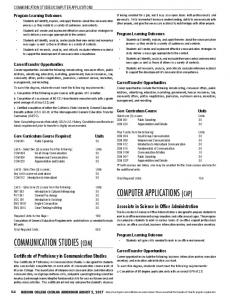
ECOTECT is an industry leading building analysis program that finally allows designers to work easily in 3D and apply all the tools neccesary for an energy efficient and sustainable future.
ecotect
Main menu
open/create document save print main menu export
main toolbar
panels panel tabs
What really sets ECOTECT apart is the visual nature of calculation feedback and its support for very early stage conceptual design as well as final design validation. Designers can start generating vital performance-related design information before the building form has even been developed. ECOTECT is very different to other more traditional CAD and simulation programmes. It is first and formost a building analysis tool - which means that its interface has to accomodate the needs of simulation and analysis functions.
eco
eco
mod
dxf
3ds
bmp
input
output
kudzai magoche ¦ 2008
Pre-setting
Go to File/User Prefences when starting a new file and this dialogue window appears. Therein the basic adjustments for using the program are made.
Site Location
Geographical location is an essential part of environmental analysis with regards to hours of sunlight and angle of solar exposure. The project page has a site location tab to pick the location of your project.
timezone point to location on world map
Modelling: Change display colours, graph and canvas fonts aselection radius. The sample grid size and default zone height can also be adjusted. Localisation: Select units for all quantities used in ECOTECT, including local currency. Cursor Snap: As in most other CAD programs, you can have several snap points activated or none at all.
zoom and grid adjustments
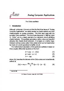
3D Editor Toolbars
specify time and date degrees latitude & longtitude
coordinates and functions
Move Rotate Scale Mirror Extrude Numeric Assign Object Extend Trim Offset Intersect Lines Join Lines Break at Nodes Fix Links Link Objects Unlink Objects Group Objects Ungroup Objects Window Void Panel Door
page tabs indicates current activity
Select Transform Menu Measure Distances Point Line Plane Partition Zone Pitched Roof Light Speaker Camera Appliance Child Object menu Add Node Delete Node
Visualise & Analysis Toolbars
Analysis Page
The Analysis page provides calculation functions for a wide range of different analysis to be carried out on the model. These fall into the following categories, each represented by a separate tab section beneath the graph:
Move Pan Rotate Pivot Zoom Perspective Distortion Straighten View
Dock Zoom In Fit Graph to Canvas Zoom Out Copy to Clipboard Store Current Graph Save Graph Data Display Legend Customise Scale
Look at Centre of View
Thermal Analysis: This dialog box can be invoked by selecting the Thermal Performance... item in the Calculate menu. The Thermal Analysis tab contains controls for calculating and displaying thermal performance information. Solar Exposure: The Solar Exposure tab contains controls for calculating and displaying information about the solar radiation incident on one or more closed planar surfaces within the model. Material Costs: The Material Costs tab contains controls for calculating and displaying total fabric costs and environmental impacts based on the geometry of the model and the materials used. Resource Consumption: The Resource Consumption tab contains controls for calculating both the consumption and production of basic resources within the building model. Reverberation Times: The Reverberation Times tab contains controls for calculating and displaying statistical reverberation time information for individual zones. Acoustic Response: This tab in the Element Library dialog displays the sound absorption coefficients for the currently selected material.
Elements
The Element Properties Dialog can be invoked by selecting the Material Library... item in the Model menu. The Element Properties dialog box controls the materials in both the current model and in the global user library. It allows you to record and adjust physical, thermal and acoustic properties
the global library is a separate file containing any number of materials that you can add to your current model
shows materials in current model
analysis panel tabs Delete Element button deletes the selected material from the current model list analysis panels
Importing 3D Geometry
ECOTECT is capable of importing a wide variety of 3D geometry file formats, including 3DS, DXF, Lightscape and VRML.
Zoom In Zoom Out Reset View Top View Front View Side View Hidden Line Wireframe
The Components List displays the existing object hierarchy in the 3D model to be imported
writing formats 1. Go to the File»Import»3D CAD Geometry... menu. A dialog box will appear, where you can select the type of 3D file format to import 2. From the Files of Type: drop-down list, select the 3D Studio (*.3DS, *.ASC, *.PRJ) option. Then click the Choose File button, and navigate to and select the CAD file. 3. A preview of the selected file will be displayed in the dialog box. Click and drag the left mouse button in the preview window to orbit around the model 4. Confirm that the scale of the is correct in relation to the original 3D geometry.
Images and Animation
the Add New Element button adds the material defined in the tabbed controls to the right as a new material in the model list
Data format + Help
Saving an image
Setting up an animation
1. Click on the Copy View to Clipboard icon 2. Select either Copy as Bitmap or Save to Disk... 3. Paste the copied bitmap in another program, or choose the location to save the image.
1. Go to the Tools » Create Animation menu item. The Create New Animation dialog box will appear
in
out
some data formats that Ecotect reads;
some data formats that Ecotect creates;
Go to File/Export.... to open the Save ECOTECT Model window, then select Windows Bitmap as the file type.
2. Determine what parts of the screen to capture (canvas only/application window), and the image size in pixels
CAD: DXF, 3DS images: BMP text: HTML, the summary page functions as a web browser
5. Under the Filename: and Directory: sections, click the button to specify a name for the animation file, and a folder location where the file will be saved.
export formats (File/Export) JPG: most common image format BMP: bitmap image file format AVI: multimedia file format, for saving video sequences presentations
3. Under the Capture Frames: section, select the prefered method 4. Under the Output Format: section, select the Save as AVI Movie option and a suitable playback rate
ECO: the program’s default format
Help the program has several guides, instructions and learning references on the Summary page and under Help on the main menu to assist in any task relating to use of the software.