Advances in Bioscience and Biotechnology, 2012, 3, 603-608 doi:10.4236/abb.2012.35078 Published Online September 2012 (http://www.SciRP.org/journal/abb/)
ABB
Effect of a rotating frame on preventing bead aggregation in a microfluidic device Jie Yang1, Peter B. Howell, Jr.2, Nastaran Hashemi1* 1
Department of Mechanical Engineering, Iowa State University, Ames, USA Center for Bio/Molecular Science and Engineering, Naval Research Laboratory, Washington DC, USA Email: *
[email protected]
2
Received 11 June 2012; revised 20 July 2012; accepted 18 August 2012
ABSTRACT Varying bead concentrations over the course of experiments have been reported by many scientists. A new device was designed and developed to eliminate bead aggregation in a syringe pump prior to flowing through a microchannel. We have modeled the effects of rotation in the absence of longitudinal flow by evenly populating the cross section of a syringe with particles, then tracking their movement due to rotation, gravity, and centripetal forces. We have shown both experimentally and numerically that the concentration of the beads remains constant over the course of experiments once the rotational device is used. However, the concentration of the beads drops significantly once no rotation is applied during the experiment. Keywords: Bead Aggregation; Microfluidics; Rotating Frame
1. INTRODUCTION Magnetic beads have become a popular means of performing affinity assays, drug delivery and DNA purification [1-4]. They can be pulled from suspension and introduced to diagnostic devices using a pump. However, varying the bead concentration during the pumping process affects the precision of the experiments [5]. In some cases, beads can be lost permanently in the pump components. Aggregation of beads in microfluidic systems, which could possibly lead to restrictions and clogging, is observed in a number of experiments. Zaytseva et al. reported that Dynabeads 1-µm beads have lower sedimentation rate compared to larger beads. They used 1-µm beads to facilitate experimental reproducibility and to prevent bead settling [6]. It is also found that beads are difficult to be loaded into a syringe and pumped di*
Corresponding author.
rectly into a rapid on-bead oligomer-target screening platform because they tend to settle quickly [7]. Therefore, Price et al. used tall, capped cartridges containing the one-bead-one-compound library to introduce beads into their platform. In a bead capture study by LundOlesen et al., it is shown that a microfluidic mixer integrated with a passive magnetic separator yields a capture-and-release efficiency less than 100% [8]. This is because the beads get stuck in the fluidic setup and never flow through system.
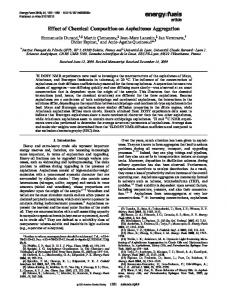
2. DESIGN We have designed and developed a device based on the dimension of a syringe pump (EW-74900-10, Cole-Parmer Instrument Company, Vernon Hills, IL) and 1 mL plastic syringe (BD Luer-Lok™, BD™, Franklin Lakes, NJ). The device consists of a motor holder and a gear. A stepper motor is mounted on the motor holder which is seated on the syringe. The outer diameter of the gear is 2.12 inches (100 tooth gear with 48 teeth/in diametrical pitch). The gear is fixed on the plastic syringe using a set screw and transmits rotational motion from the motor shaft to the syringe. The device provides continuous mixing of the beads with the solution while they are being introduced to the channel. Figure 1(a) shows the components of the device including the motor holder, the gear, and the whole assembly. The device was built in aluminum. The stepper motor and the gear were fixed on the motor holder and on a 1 mL plastic syringe respectively using screws (Figure 1(b)). The ability of the device to prevent bead aggregation is dependent on several factors, including the angular velocity, the volumetric flow rate of the pump and consequently the time that the beads remain in the syringe, and the density of the beads. The beads need to stay suspended in order to observe no variation in the concentration of the beads flowing into the channel. EFD precision dispensing tip (PTFE-coated, EFD Inc., East Providence,
Published Online September 2012 in SciRes. http://www.scirp.org/journal/abb
J. Yang et al. / Advances in Bioscience and Biotechnology 3 (2012) 603-608
604
(a)
(b)
Figure 1. (a) View of the motor holder and gear assembly that transmits power from the motor to the syringe. The outer diameter of the gear is 2.12 inches (100 tooth gear with 48 teeth/in diametrical pitch); (b) Picture of the syringe rotator device built in aluminum.
RI) is placed in an aluminum tube just big enough to slide over the needle. The other end of the aluminum tube is connected tightly to the silicone tubing. The aluminum tubing plays the role of transforming the rotary motion to the fixed silicone tubing by sliding over the teflon coating of the needle and teflon seals the media passing through the aluminum tube. Rotating unions, also known as rotary coupling, can be used to transform the rotating motion of the syringe to the stationary silicone tubing as well.
3. THEORY At any given time the particles in solution migrate downward at a rate of, w
2 p f grp2 9
(1)
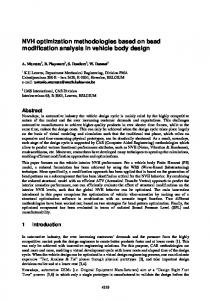
where w is the settling velocity, p is the density of the particle, f is the density of the fluid, g is the gravitational acceleration, rp is the radius of the particle, and is the fluid viscosity. The flow was modeled by solving the incompressible Navier-Stokes equations using the PISO algorithm [9]. The openFOAM computational framework was used for this task. The fluids were modeled in three dimensions, although only two-dimensional representations will be shown here. In Figure 2, the vertical component of the flow velocity is shown in the region of the constriction of the Luer connection. The solid line is the contour of the velocity of 2.34 μm/s, which is approximately the settling velocity of the beads used in this study. Beads below this contour never experience an upward velocity sufficient to carry them upward to the outlet. While initially, there are beads within and above the contour, as Copyright © 2012 SciRes.
Figure 2. Vertical velocity component of flow at the outlet of the syringe under no-rotation conditions. Red represents a positive component and cyan represents negative. Outline of the syringe and contour representing 2.34 μm/s are in white.
the experiment progresses, the beads approaching the outlet will increasing be below it. The purpose of the rotation is to maintain beads within a region that will allow them to be pulled into the outlet. At the beginning of an experiment, the syringe is filled with an evenly distributed particle suspension, mounted on the pump, and rotated at angular velocity α. It is assumed that at the rotation rates used in these experiments (α 1 radians/s) centripetal acceleration can be neglected. Also to a first approximation, it can be assumed that rotational momentum is quickly transferred from the syringe barrel to the fluid so that the fluid is rotating in synchrony with the syringe for the bulk of the experiABB
J. Yang et al. / Advances in Bioscience and Biotechnology 3 (2012) 603-608
mental time. It is also assumed that the settling particles do not significantly perturb the fluid or the movement of other particles. From the reference frame of the rotating fluid, particles settle at a constant velocity, but in a continuously rotating direction. The resulting track, assuming no collisions with the wall, is a circle of radius rt
w
it will be forced back to the outermost track by further collisions with the wall. There is a lateral concentration factor, given by R F R w
(2)
605
2
(3)
where R is the radius of the syringe. One could imagine a situation where particles of variable values of w are separated longitudinally due to differential sampling of the longitudinal flow streams in a manner similar to field flow fractionation. The use of multiple outlets could also be used for continuous separation of particle populations. In the current configuration, however, the end of the syringe is sampling the entire width of the fluid in the syringe, and so the concentration effect does not effect the final concentration of the beads exiting the syringe. Instead, the concentration of beads into the rotating inclusion zone serves it ensure that no bead remains below the region that allows it to be carried of the syringe by the fluid motion.
From the laboratory reference frame, all the uninterrupted bead tracks are concentric around a center point, Ci, centered rt away from the center of rotation (Figure 3(a)). As can be seen in the figure there is a fully eccentric annular exclusion region (shown in grey). Beads initially found in this region will collide with the wall during the first revolution, then be carried by the rotation until they pass through the vertical whereupon gravity again pulls them away from the wall. The net effect is that any beads in the exclusion zone become concentrated into the outmost uninterrupted track. Collisions or Brownian motion may carry the beads further into the uninterrupted bead tracks, but any bead that moves out of
(a)
(b)
(c)
(d)
(e)
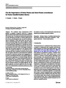
Figure 3. Simulations of the particle distribution in the cross-section of a syringe after 60 minutes at (left to right) no rotation; 0.0005 rpm; 0.01 rpm; 1 rpm. The particles were initially placed evenly throughout the syringe (1 rpm shows no change after 60 minutes).
Copyright © 2012 SciRes.
ABB
J. Yang et al. / Advances in Bioscience and Biotechnology 3 (2012) 603-608
606
The Coriolis force was neglected in this study. It is also shown by Detzel et al. that for low system rotations (