duty cycle of the sleep schedule and the frame rate affect the overall performance of a ... Software controlled frame rate feature allows video streams with rates ...
Effect of Sleep Schedule and Frame Rate on the Capabilities of Video Sensor Networks Atay Ozgovde, Ilker Demirkol, Cem Ersoy Network Research Laboratory Department of Computer Engineering Boˇgazic¸i University Bebek 34341 Istanbul, Turkey E-mail: {ozgovde,ilker,ersoy}@boun.edu.tr
Abstract—Visual data carried on Video Sensor Networks (VSNs) creates unique challenges due to the limited hardware of the sensors. In this paper, we study the capabilities of VSNs using currently available technology by investigating how the duty cycle of the sleep schedule and the frame rate affect the overall performance of a VSN. The trade-off between sensor video quality and the received frame rate at the sink is depicted which is an important measure for the application level performance. Using extensive simulations run with realistic parameters, it is shown that increasing the video quality to enhance the application level detection and/or tracking performance works only up to a certain extent.
I. I NTRODUCTION Video Sensor Networks (VSNs) are the new members of the Wireless Sensor Network (WSN) family in which multirate streaming data traffic and related Quality of Service (QoS) requirements result in new problems that require novel solutions. Traditional wireless sensor networks are generally tuned for scalar data that is being relayed through multihop routes towards the data sink. Therefore, previously proposed WSN protocols may be insufficient for VSNs as the video streams require very large bandwidth compared to scalar data such as temperature readings. Additionally, due to the nature of the video, the streams have always realtime requirements. Moreover, since the logical unit of the communicated data becomes video frames, either successful delivery of all or a large percentage of packets of a video frame are required to be delivered to the sink node. Majority of the available video coding schemes such as MPEG are designed to have computationally intensive video processing at the sender and less computational effort at the receiving side. However, the requirements in WSNs are exactly the opposite. Sensor nodes have less computational power and energy capacities, on the other hand, the data sink is usually assumed to be computationally more powerful and has unlimited source of energy. This makes the complicated inter-frame coding based video processing techniques infeasible for the VSNs [1]. For that reason, a very low frame rate video is assumed which is basically a sequence of images to be transferred to the This work is supported by The Scientific and Technological Research Council of Turkey (TUBITAK) under the grant number 106E082.
sink. However, in order for individual images to be useful for tracking or identification purposes, a certain percentage of the packets are required to be delivered to the sink. Introducing a sleep schedule is required to increase the energy efficiency of a WSN. For traditional scalar type of data traffic, lowering the duty cycle results in a higher energy efficiency at the expense of increased delay [2]. However, in the context of video traffic, changing the duty cycle not only affects the delay but also the throughput of the system, which in turn affects the object identification or tracking quality. In general, due to the congestion in the network and the limited buffers of the sensor nodes, not all of the packets will be delivered to the data sink. For that reason, increasing the sensor video quality generated at individual nodes does not necessarily entail an increase in the received video quality at the data sink. In this work, we explore the limitations on VSNs in terms of the carried traffic rate and application level requirements. We run simulations with realistic parameters to explore the effect of the duty cycle and the frame rate on the performance of VSNs. It is shown that higher video quality can increase application level performance only within a bounded operational region. II. S YSTEM M ODEL AND S IMULATION PARAMETERS To asses the performance behavior of VSNs, simulations are run under OPNET simulation environment [3] with realistic parameters reflecting the hardware and software capabilities that are currently available. The deployment is done with single sink node located in the geometric center of the surveillance area. Nodes are equipped with image modules composed of cameras capable of producing and compressing video images [4],[5]. Raw image format is software adjustable and in our simulations SQCIF (128 x 96) format is assumed. The image module employs intra-frame encoding which results in compressed images of size 10 Kbits. Predictive encoding alternatives such as ISO MPEG or H.26X cannot practically be used in VSNs due to the high complexity involved [6]. Distributed source coding techniques are promising alternatives for encoding video in VSNs as they exploit the inter-frame redundancy with affordable complexity in the sensor nodes [1]. However, due to the lack of practical implementations yet
available, we resort to the JPEG compression available on the image module. Software controlled frame rate feature allows video streams with rates between 1 − 12 fps to be introduced to the network by each individual sensor node. Event triggered data generation is simulated where the triggering event is the visual detection of the target. Since the cameras employed support the background subtraction feature, they only produce an image when the scenery changes significantly. Triggering occurs when the target is within camera detection range of 30 m and is within the Field of View (FOV) of 52 degrees. The target is assumed to move within the surveillance area according to the Random Waypoint Mobility model where the target velocity is set to 10 m/s and pause time is set to 0 seconds. Crucial simulation parameters are tabulated in Table I. Data transfer at the frame level to the sink is assumed to be done in the application layer whereas packet level communications at the network and MAC layers are handled with GPSR [7] and SMAC [8], respectively.
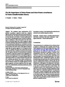
the system by varying the image resolution and the camera frame rate. In our case, we fix the image resolution since a lower resolution may not be tolerated by the identification application, whereas a higher resolution results in frame sizes that cannot effectively be carried in the network. Therefore, in the simulations the frame rate of the cameras on the sensors is varied to alter the video quality throughout the network. As depicted in Fig. 1, increasing the video quality in the sensors only pays-off up to a saturation point, after which the throughput drops, hence the average frame rate received at the sink decreases. To show the limiting factors on the throughput, the experiments are repeated for three different duty cycle values. Fig. 1 exhibits that the saturation point is dependent on the duty cycle of the system. A higher duty cycle value enables higher network service rate by handling more packet transmission per unit time. Here, an implicit energy trade-off is also observed since increasing the duty cycle increases the energy consumption in the network.
TABLE I S IMULATION PARAMETERS
0.8 Duty Cycle = 0.05
Value 400 x 400 m2 60 Nodes Uniform random 10 Kbits 1 KBits 1 to 12 fps 52 deg. 30 m 250 Kbps 20 Kbits Random Waypoint
III. E FFECT OF S LEEP S CHEDULE AND F RAME R ATE IN V IDEO S ENSOR N ETWORKS Several simulation runs are performed with different duty cycles and the sensor camera frame rates. At each run, the total number of frames created is recorded along with the number of received video frames at the sink. Table II shows the average aggregate frame traffic rates achieved versus the camera frame rate based on the target detection scenario described in Section II. TABLE II AVERAGE VIDEO TRAFFIC TRIGGERED IN THE NETWORK Camera Frame Rate (fps) 1 2 5 8 10 12
Average Traffic Created (fps) 0,1502 0,2994 0,7431 1,2002 1,4805 1,7844
A. Effective Traffic Carried in the Network Generally, higher video quality is required for better VSN application performance. Video quality can be adjusted in
Duty Cycle = 0.50
0.7
Average Video Traffic Received at Sink Node (fps)
Paremeter Surveillance Area Network Size Deployment Type Video Frame Size Packet Size Camera Frame Rate Field of View Camera Detection Range Bandwidth Buffer size Target Mobility Model
Duty Cycle = 0.95
0.6
0.5
0.4
0.3
0.2
0.1
1
2
3
4
5
6 7 Camera Frame Rate (fps)
8
9
10
11
12
Fig. 1. Effect of sensor video quality (frame rate) on the received frame rate at the sink.
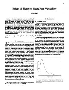
B. Delivery Ratio As the compressed video includes dense information, a frame can be defined as lost after a certain drop percentage for the packets that belong to that frame. In our simulations we set that threshold to 10%, i.e. if more than 10% of packets that belong to a frame are dropped, then that frame could not be recovered and is labeled as a lost frame. Fig. 2 shows the successful frame delivery ratio for different sensor frame rates under different duty cycles. Depending on the QoS requirements of the application, the maximum allowed sensor frame rate can be extracted from this figure. For instance, if the application requirement is 90% successful frame delivery ratio, then for 50% duty cycled network operation, the sensor frame rate must be 2.5 fps or less to achieve that QoS requirement. To further understand how the duty cycle introduced by the sleep schedule affects the application level performance, we need to examine the main cause of the packet drops
1
1
0.95
Duty Cycle 5% Duty Cycle 50% Duty Cycle 95%
0.9 Succesful Frame Delivery Ratio
0.9
Succesful Frame Delivery Ratio
0.8
0.7
0.6
0.85 0.8 0.75 0.7 Duty Cycle 5%
0.65
Duty Cycle 50%
0.5
Duty Cycle 95%
0.6 0.4
0.55 0.5
0.3
1
2
3
4
5
6 7 Camera Frame Rate (fps)
8
9
10
11
12
0.2
Fig. 4. 0.1
1
2
3
Fig. 2.
4
5
6 7 Camera Frame Rate (fps)
8
9
10
11
Successful frame delivery ratio for the buffer size of 250 Kbits.
12
simulation runs are repeated for the increased buffer size of 250 Kbits in this section.
Successful frame delivery ratio.
0.9
3 Duty Cycle = 0.05 Duty Cycle = 0.50 Duty Cycle = 0.95
0.8
Duty Cycle 50%, Buffer 250 Kbits
2.5 Average Source to Sink Latency (sec)
Duty Cycle 95%, Buffer 250 Kbits
Frame Drop Rate at Source Nodes
0.7
0.6
0.5
0.4
Duty Cycle 50%, Buffer 20 Kbits Duty Cycle 95%, Buffer 20 Kbits
2
1.5
1
0.3
0.5
0.2
0
1
2
3
4
5
6 7 Camera Frame Rate (fps)
8
9
10
11
12
0.1
0
0
2
4
6 8 Camera Frame Rate (fps)
10
12
14
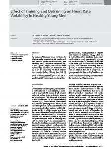
Fig. 3. Ratio of aggregate dropped traffic at source nodes to aggregate created traffic.
experienced in the network. Fig. 3 depicts that as the duty cycle is lowered, considerable amount of video traffic is dropped at the source nodes. A sensor node operating at a low duty cycle, upon detecting the target begins to accumulate video frames as the probability to have a neighbor awake gets lower and buffer overflow occurs. More concisely put, by decreasing the duty cycle one actually limits the video traffic that can be introduced into the system. C. Effect of Buffer Size Current sensor nodes generally have around 60 Kbits of RAM available [9]. Our choice of 20 Kbits buffer size is based on the assumption that available RAM area that is not used by the communications stack and the application code can be allocated as a buffer to handle the images conveyed from the camera module. However, it is possible to increase the physical RAM size to create more buffer for image handling at the expense of increased costs. Here, we explore the effect of increasing buffer size to alleviate the overflow problem. The
Fig. 5.
Effect of increased buffer size for duty cycles of 50% and 95%.
As shown in Fig. 4, successful delivery ratio is considerably higher for the new buffer size. The main reason for this behavior is that high drop rates at source nodes are now eliminated, i.e. the video traffic is now being let into the network with a much less loss rate. How the increased buffer affects the average delay in the system is shown in Fig. 5 and Fig. 6. Here, the delay experienced by the packets as they travel from source to sink is measured. As expected, the observed end-to-end delay is increased for the higher buffer size. However, as seen from the figures, the duty cycle setting is a determinant factor for the end-to-end delay. For low buffer size, the maximum source to sink delay is bounded by 0.25 seconds, which is a sufficient value for delay-intolerant applications. For increased buffer size, different delay characteristics are observed as a function of the duty cycle applied. For duty cycle values of 50% and 95%, the delay observed is bounded by 3 seconds, which still may be considered as acceptable for various VSN applications. The delay also varies with the increased frame rate which means that the applications that require stricter delay bounds should operate at lower frame rates for any duty cycle setting. The delay observed for the lowest duty cycle value is depicted in Fig. 6. Here, it is clearly seen that increasing the
[6] I. Akyildiz, T. Melodia, and K. Chowdhury, “A survey on wireless multimedia sensor networks,” Computer Networks, vol. 51, no. 4, pp. 921–960, 2007. [7] B. Karp and H. T. Kung, “GPSR: greedy perimeter stateless routing for wireless networks,” in MOBICOM, 2000, pp. 243–254. [8] W. Ye, J. S. Heidemann, and D. Estrin, “An energy-efficient MAC protocol for wireless sensor networks,” in INFOCOM, 2002. [9] “Xbow.” [Online]. Available: http://www.xbow.com
55 50 Duty Cycle 5%, Buffer 250 Kbits
Average Source to Sink Latency (sec)
45
Duty Cycle 5%, Buffer 20 Kbits 40 35 30 25 20 15 10 5 0
1
Fig. 6.
2
3
4
5
6 7 Camera Frame Rate (fps)
8
9
10
11
12
Effect of increased buffer size for duty cycle value of 5%.
buffer size puts the system in a saturated state, as the camera frame rate goes above 1 fps. Although, successful delivery ratio depicted in Fig. 4 indicates that more than 75% of the frames are received at the sink even for 12 fps, due to high buffering capacity combined with the limited communication capacity imposed by the low duty cycle, packets are received at sink with very high delays. IV. C ONCLUSION AND F UTURE W ORK In this work, capabilities and limitations of a VSN which is implemented with the currently available technology is explored. It is observed that sending images more frequently from individual sensors can achieve better application level quality only within a bounded operational region. This region is determined by the available constraints on the sensor hardware (communication bandwidth, buffer size) and also by the sleep schedule introduced. Simulation runs with realistic parameters are conducted to show the limits of the carried video traffic in relation to the application level requirements. It is observed that, especially for VSN, the limited buffer capacity of the sensor nodes results in high packet drop rates. The method of increasing the buffer size is also investigated which unfortunately incurs high packet delays that are not acceptable for the delay-intolerant applications. As the future work, the relationship between varied duty cycles and the total energy consumption can be quantified in terms of network lifetime. Thus, the tradeoff between increased throughput and energy consumption can be explored further. R EFERENCES [1] Z. Xiong, A. Liveris, and S. Cheng, “Distributed source coding for sensor networks,” Signal Processing Magazine, IEEE, vol. 21, no. 5, pp. 80–94, 2004. [2] W. Ye, J. S. Heidemann, and D. Estrin, “Medium access control with coordinated adaptive sleeping for wireless sensor networks,” IEEE/ACM Trans. Netw., vol. 12, no. 3, pp. 493–506, 2004. [3] “Opnet Modeler,” 2007. [Online]. Available: http://www.opnet.com/products/modeler/home.html [4] I. Downes, L. Rad, and H. Aghajan, “Development of a mote for wireless image sensor networks,” in Proc. of COGnitive systems with Interactive Sensors (COGIS), Paris, France, March, 2006. [5] P. Kulkarni, D. Ganesan, P. J. Shenoy, and Q. Lu, “SensEye: a multi-tier camera sensor network.” in Proceedings of the 13th ACM International Conference on Multimedia, November 6-11, 2005, Singapore. ACM, 2005, pp. 229–238.