Materials Science and Engineering A 528 (2011) 4683–4689
Contents lists available at ScienceDirect
Materials Science and Engineering A journal homepage: www.elsevier.com/locate/msea
Effect of friction stir welding parameters on the microstructure and mechanical properties of the dissimilar Al–Cu joints P. Xue, D.R. Ni, D. Wang, B.L. Xiao, Z.Y. Ma ∗ Shenyang National Laboratory for Materials Science, Institute of Metal Research, Chinese Academy of Sciences, 72 Wenhua Road, Shenyang 110016, China
a r t i c l e
i n f o
Article history: Received 13 December 2010 Received in revised form 19 February 2011 Accepted 21 February 2011 Available online 26 February 2011 Keywords: Friction stir welding Dissimilar joint Intermetallic compounds Microstructure Mechanical properties
a b s t r a c t Butt joints of 1060 aluminum alloy and commercially pure copper were produced by friction stir welding (FSW) and the effect of welding parameters on surface morphology, interface microstructure and mechanical properties was investigated. The experimental results revealed that sound defect-free joints could be obtained under larger pin offsets when the hard Cu plate was fixed at the advancing side. Good tensile properties were achieved at higher rotation rates and proper pin offsets of 2 and 2.5 mm; further, the joint produced at 600 rpm with a pin offset of 2 mm could be bended to 180◦ without fracture. The mechanical properties of the FSW Al–Cu joints were related closely to the interface microstructure between the Al matrix and Cu bulk. A thin, uniform and continuous intermetallic compound (IMC) layer at the Al–Cu butted interface was necessary for achieving sound FSW Al–Cu joints. Stacking layered structure developed at the Al–Cu interface under higher rotation rates, and crack initiated easily in this case, resulting in the poor mechanical properties. © 2011 Elsevier B.V. All rights reserved.
1. Introduction The joints of dissimilar materials are widely used in industrial applications due to their technical and beneficial advantages [1]. Aluminum and copper are two common metals in the electric power industry, and the Al–Cu transition pieces are widely used to transmit the electricity. Due to the difficulties in making an electrically stable bolted joint between these two dissimilar metals, much effort has been focused on welding aluminum to copper in the last decades [2]. However, the dissimilar combination of aluminum and copper is generally difficult for fusion welding. This is because of the wide difference in their physical, chemical and mechanical properties, and the tendency to form brittle intermetallic compounds (IMCs). Therefore, the solid-state joining methods, such as friction welding, roll welding, and explosive welding have received much attention [2–7]. These methods, however, have a few drawbacks. Fox example, friction welding and roll welding lack versatility, and explosive welding involves in the safety problems. In the past decade, much attention has been directed towards friction stir welding (FSW) [8]. Recently, attempts have been made to join dissimilar materials through FSW, such as aluminum to steel, aluminum to magnesium, and aluminum to copper [9–20]. It was reported that sound dissimilar FSW Al–Cu joints were difficult to achieve, and the joints usually failed at the nugget zone or along
the interface between the two materials during the mechanical tests [13–15]. Ouyang et al. [14] attributed the poor weld ability to the various brittle IMCs formed in the nugget zone. Lee and Jung [15] suggested that the formation of Al2 O3 and CuO layers resulted in lower tensile strength besides the brittle IMCs. In our previous study [17], sound FSW Al–Cu joint was obtained by offsetting the tool to the aluminum side under a lower heat input condition. The formation of a thin, continuous and uniform IMC layer produced the excellent metallurgical bonding on the Al–Cu interface, and no oxide layer was found. It is well documented that many parameters, such as tool offsetting, rotation rate and traverse speed, influenced the weld properties of the dissimilar FSW joints [18–22]. Limited studies have been performed on the FSW dissimilar Al–Cu joints till now, and systematic research on the FSW parameters is still lacking. Therefore, it is worthwhile to study the effect of the FSW parameters on the microstructure and mechanical properties of the dissimilar FSW Al–Cu joints. In this paper, various FSW butt Al–Cu joints were produced under different fixed locations, pin offsets, and rotation rates, and the microstructure and mechanical properties were studied in detail. The purpose of this study is to elucidate the correlation between the FSW parameters and bonding strength in dissimilar FSW joints. 2. Experimental procedures
∗ Corresponding author. Tel.: +86 24 83978908; fax: +86 24 83978908. E-mail address:
[email protected] (Z.Y. Ma). 0921-5093/$ – see front matter © 2011 Elsevier B.V. All rights reserved. doi:10.1016/j.msea.2011.02.067
1060 aluminum and commercially pure copper (∼99.9% purity) plates 5 mm in thickness, 300 mm in length, and 70 mm in width
4684
P. Xue et al. / Materials Science and Engineering A 528 (2011) 4683–4689
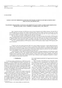
Fig. 1. Schematic illustration to show the relationship between the pin position and the coordinate.
were butt-welded using a gantry FSW machine (China FSW Center). The welding tool used in this study was made of heat-treated tool steel and had a shoulder 20 mm in diameter and a pin 6 mm in diameter and 4.8 mm in length. Welds were made with a counter clock-wisely rotating pin at rotation rates of 400–1000 rpm and a constant traverse speed of 100 mm/min. During the welding processes, several pin offsets from 0 mm to 3 mm were used. For convenience, in this study, an offset of 0 mm denotes the position where the pin just located at the butt line, and 3 mm is at the position where the pin side face is located at the faying surface of Cu, as schematically shown in Fig. 1. Microstructural characterization and analyses were carried out by optical microscopy (OM), X-ray diffraction (XRD), and scanning electron microscopy (SEM), complemented by energy-dispersive spectroscopy (EDS). Large transverse tensile specimens with a gauge length of 40 mm and a width of 10 mm were machined perpendicular to the FSW direction. Tensile tests were carried out at an initial strain rate of 1 × 10⁻³ s−1 . Three-point bending tests were performed over a 40 mm span using a universal testing machine with a crosshead speed of 0.5 mm min−1 . 3. Results and discussion 3.1. The effect of fixed location on the weldability of the joints Different from the conventional FSW joints, fixed location of the welded plates is also an important parameter for the FSW dissimilar joints. Fig. 2 shows the surface morphologies and cross-sectional macrostructures of the FSW Al–Cu joints for the different fixed locations at a welding parameter of 800 rpm – 100 mm/min with a pin offset of 3 mm. It is clear that when the Cu plate was fixed at the advancing side, sound weld surface was achieved, as shown in Fig. 2(a). However, when the Cu plate was fixed at the retreating side, the weld surface was very poor and a certain amount of Al
Fig. 3. Schematic illustration of the fixed location of the hard material (a) at the AS with clock-wise rotation of a pin, (b) at the RS, and (c) at the AS with a counter clock-wise rotation of a pin.
material was extruded out from the nugget zone (Fig. 2(b)). Furthermore, connected tunnel defect was observed on the weld surface (Fig. 2(c)). From the cross-sectional macrograph shown in Fig. 2(d), it is clear that no defects could be observed when the Cu plate was fixed at the advancing side. However, when the Cu plate was fixed at the retreating side, an obvious volume defect which was the cross section of the tunnel was observed at the top side of the nugget zone (Fig. 2(e)). When a hard material and a soft material were friction-stirwelded, previous studies indicated that the weld quality was clearly influenced by the fixed location [19–22]. From the above observation in this study, sound weld surface could be obtained when the hard Cu plate was fixed at the advancing side. In a study of FSW Al–Fe joints, Watanabe et al. [19] reported that a long crack line was observed on the weld surface when the pin rotation direction was counter clock-wise, and sound weld surface could be obtained in a reversed rotating direction. Actually, the counter clock-wise rotating direction is not the essential reason of the poor surface quality. The key factor is where the hard plates (Cu plate in this study) fixed during the FSW process. Though the hard plates were fixed at the retreating sides in some studies, sound joints were usually obtained when the hard plates were fixed at the advancing sides [19,20]. Fig. 3 shows the schematic illustration explaining the effect of the fixed location on the weldability of FSW dissimilar welds. Fig. 3(a and b) shows the welding manners Watanabe et al. [19] chosen for FSW Al to Fe, and the two welding manners used in this study are shown in Fig. 3(b and c). Among these three welding manners, defect-free joints could be obtained by the manners shown in Fig. 3(a and c). Though the rotating directions are different in Fig. 3(a and c), the hard plates (Fe and Cu, respectively)
Fig. 2. Surface morphologies of the FSW Al–Cu joints under a welding parameter of 800 rpm – 100 mm/min and a pin offset of 3 mm for the Cu plate fixed at (a) advancing side (AS), (b) retreating side (RS), (c) magnified morphology of the tunnel defect as shown by the rectangle in (b), and cross-sectional macrostructures of the joints for the Cu plate fixed at (d) AS and (e) RS.
P. Xue et al. / Materials Science and Engineering A 528 (2011) 4683–4689
4685
Fig. 4. Surface morphologies of the FSW Al–Cu joints under a welding parameter of 800 rpm – 100 mm/min for pin offsets of (a) 2.5 mm, (b) 2 mm, (c) 1 mm, (d) 0 mm, and cross-sectional macrostructure of the joints for pin offset of (e) 2.5 mm and (f) 1 mm.
are all fixed at the advancing side. During the FSW process, the materials were transported from the retreating side to the advancing side behind the pin where the weld was formed [23,24]. The hardness of the Cu and Fe were larger than that of the Al, and the pin stirred mainly in the Al base during FSW, so the material flow occurred mainly in the soft Al base. If the hard material was fixed at the retreating side (Fig. 3(b)), the hard material was difficult to transfer to the advancing side because the hard material hardly flew. In this case, a large volume defect would form as shown in Fig. 2(e), and the excessive soft material would be extruded out from the nugget zone (Fig. 2(b)). However, when the softer material was fixed at the retreating side (Fig. 3(a and c)), the soft material was transported to the advancing side easily, and the material flow cycle in the nugget zone was performed normally. Furthermore, as discussed by Watanabe et al. [19], the materials were mixed at the activated and un-activated regions when the hard material was fixed at the advancing and retreating sides, respectively. Therefore, the dissimilar materials were mixed easily when the hard material was fixed at the advancing side, resulting in the sound weld quality.
dissimilar welds would be produced under a larger pin offset to the softer material. This should be related to the huge differences in physical, chemical and mechanical properties between the dissimilar materials. When the pin offset was larger, only few Cu pieces with relatively small size were scratched from the Cu bulk. It was easy for the small Cu pieces to mix into the Al base and react with the Al base in the nugget zone, and therefore sound metallurgical bonding would be obtained at the Al–Cu interface as discussed in our previous paper [17]. On the other hand, many large Cu pieces were stirred into the nugget zone at a smaller pin offset. The Cu pieces were harder than the Al matrix, therefore, the large Cu pieces were hard to deform and flow in the Al matrix, and the mixing between the large Cu pieces and the Al matrix would be very difficult. This led to the poor surface bonding and the formation of many voids as shown in Fig. 4(d and f). Moreover, when the pin offset was smaller, more Al–Cu IMCs would be formed because the more Cu pieces were stirred into the nugget zone. Thus the joining between the Al and Cu became poor due to the brittle nature of the IMCs [14].
3.2. The effect of pin offset on the weldability of the joints
3.3. The effect of rotation rate on the weldability and microstructure of the joints
FSW is ordinarily conducted through inserting the rotating pin in the weld line of butted plates. Previous studies proved that for FSW dissimilar materials, poor joints were obtained using this traditional procedure, and the pin offset to the softer materials was usually adopted to achieve the defect-free joints [13,14]. Therefore, we chose various pin offsets in this study to investigate the optimum value of the pin offset under a welding parameter of 800 rpm – 100 mm/min. The surface morphologies and crosssectional macrostructures of the FSW Al–Cu joints for different pin offsets are shown in Fig. 4. When the pin offset was equal to or larger than 2 mm, good surface morphologies could be obtained, as shown in Figs. 2(a) and 4(a and b). However, the surface quality became poorer under the smaller pin offsets. Many cracks were observed obviously on the weld surface for a pin offset of 0 mm which was the traditional FSW manner (Fig. 4(d)). From the crosssectional macrograph shown in Fig. 4(e), sound defect-free joints could be obtained at a larger pin offset of 2.5 mm, and the nugget zone consisted of a mixture of the Al matrix and Cu pieces. However, at a smaller pin offset of 1 mm, several large Cu pieces were mixed with the Al matrix in the nugget zone, and many voids could be observed (Fig. 4(f)). Therefore, sound defect-free welds could be achieved only at larger offsets, no less than 2 mm in this study. In FSW of dissimilar materials, the pin offset was an important parameter influencing the weld quality [15,17,19,21]. The results in this study and most previous studies [15,19] proved that sound
Fig. 5 shows the surface morphologies of the FSW Al–Cu joints under different rotation rates at a constant pin offset of 2 mm. As shown in Fig. 5(a), the sound weld surface was obtained at a lower rotation rate of 400 rpm. However, the weld surface became poorer as the rotation rates increased (Figs. 4(b) and 5(b and c)). The poor weld surface should be attributed to the excessive IMCs formation under the enhanced reaction between Al and Cu at higher rota-
Fig. 5. Surface morphologies of the FSW Al–Cu joints under a pin offset of 2 mm for rotation rates of (a) 400 rpm, (b) 600 rpm, (c) 1000 rpm.
4686
P. Xue et al. / Materials Science and Engineering A 528 (2011) 4683–4689 Table 1 Tensile properties and fracture locations of the FSW Al–Cu joints at various rotation rates and pin offsets.
Fig. 6. X-ray diffraction patterns of the nugget zone welded at rotation rates of 400 and 1000 rpm.
tion rates. This can be observed from the XRD results in the nugget zone, as shown in Fig. 6. At the lower rotation rate of 400 rpm, the characteristic diffraction peaks of the Al–Cu IMCs were not obvious, indicating that only a few Al–Cu IMCs formed in this case. However, at the higher rotation rate of 1000 rpm, obvious characteristic peaks of Al2 Cu and Al4 Cu9 IMCs were observed. Previous TEM observations indicated that a few AlCu IMCs formed in the nugget zone at 600 rpm [17], so a small amount of AlCu phases would also form at a higher heat input condition of 1000 rpm, though no obvious diffraction peaks of the AlCu phase were detected. Fig. 7 shows the cross-sectional macrostructure of the FSW Al–Cu joints at various rotation rates. At the lower rotation rates of 400 and 600 rpm, the Cu pieces detached from the Cu bulk were mainly distributed at the bottom and retreating side of the nugget zone, which was the result of material flow under the effect of the threaded pin [23]. Moreover, only few fine Cu pieces were found near the Al–Cu interface at lower rotation rates. Many voids could be observed in the nugget zone at the rotation rate of 400 rpm (Fig. 7(a)); however, sound defect-free joint was obtained at the rotation rate of 600 rpm (Fig. 7(b)). The formation of the voids should be related to the insufficient reaction at the lower rotation rate. When the rotation rates were higher, the stirring action of the pin became stronger, so more Cu pieces were scratched from the Cu bulk and distributed in the whole nugget zone. While a lot of Cu pieces were distributed at the bottom of the nugget zone, many Cu pieces were observed near the Al–Cu interface at the higher rotation rates of 800 and 1000 rpm (Fig. 7(c and d)). Fig. 8 shows the magnified SEM microstructure of the Cu pieces in the nugget zone at various rotation rates. At the lower rotation rate of 400 rpm, many voids and cracks were observed in the Al matrix (Fig. 8(a)). No obvious IMC layer which was an indication of good metallurgical bonding [17] formed around the Cu pieces. Instead, cracks could be found around them, as shown in Fig. 8(b). This indicates that the Cu pieces were hard to react and mix with the Al matrix at the low rotation rate of 400 rpm. At the higher rotation rate of 1000 rpm, strongly stirring and enhanced friction between the shoulder and the welded materials made the temperature in the nugget zone very high compared to that at the lower rotation rates. Sufficient reaction between Al and Cu pieces was achieved in this case, and no defects were observed in the nugget zone, as shown in Fig. 8(c). Around the Cu pieces, obvious interfacial layers associated with the Al–Cu IMCs [17] could be observed, and many Cu particles with stacking layered structures were distributed in the Al matrix (Fig. 8(c and d)). EDS results indicated that the chemical compositions at locations a, b, and c in Fig. 8(d) were approximately equal to those of Al2 Cu, Al4 Cu9 and Cu, respectively.
Rotation rate (rpm)
Offset (mm)
UTS (MPa)
Fracture location
400
2 2.5 3
95 70 70
Nugget Interface Interface
600
2 2.5 3
110 98 87
Al HAZ Interface Interface
800
2 2.5 3
103 99 62
Al HAZ Al HAZ Interface
1000
2 2.5 3
103 105 87
Al HAZ Al HAZ Interface
Therefore, these stacking layered structures consisted of Cu pieces and Al–Cu IMCs. Of course, many small Cu pieces had already been transformed into the IMCs according to our previous study [17]. It is clear that enhanced reaction between Al and Cu pieces took place at higher rotation rates. The microstructures of the Al–Cu butted interfaces at various rotation rates are shown in Fig. 9. At the lower rotation rates of 400 and 600 rpm, the interfaces were characterized by the thin, uniform and continuous IMC layers, and the thickness were estimated to be 0.3 m and 0.8 m, respectively (Fig. 9(a and b)). When the rotation rates increased to 800 and 1000 rpm, the IMC layer was not uniform in thickness at the whole interface. The minimum thickness of the IMC layers was estimated to be 1.1 m and 1.4 m, respectively, and the maximum thickness could reach 3 m at 1000 rpm (Fig. 9(c and d)). It should be emphasized that many stacking layered structures were also observed at the interfaces at the higher rotation rates of 800 and 1000 rpm, as shown in Fig. 9(d). This was more obvious when a large Cu piece existed near the interface (Fig. 10). It is clear from Fig. 10 that a very thick stacking layered structure of ∼30 m could be observed at the interface. The stacking layered structure was similar to that in the nugget zone, and also consisted of Cu and IMCs. Ouyang et al. [14] claimed that the direct FSW of 6061 Al alloy to copper was difficult due to the brittle nature of the IMCs formed in the nugget zone. The formation of the IMCs was related closely to the reaction temperature in the nugget zone which was decided by the rotation rate in this study. Therefore, poor weld surface were obtained when excessive IMCs formed at the higher rotation rates, as shown in Fig. 5. However, at the lower rotation rate of 400 rpm, the reaction between Al and Cu was insufficient because of the low reaction temperature. Then, the defects formed easily in the nugget zone due to the difficulty in mixing the hard Cu pieces and Al matrix [18,19]. It is clear from Figs. 9 and 10 that the bonding conditions of the interface between the Cu bulk and Al matrix were influenced by the rotation rates greatly. The thickness of the IMC layer became larger as the rotation rates increased. This was due to that the enhanced reaction between Al and Cu occurred at higher rotation rates. Moreover, the stacking layered structures developed at the higher rotation rates of 800 and 1000 rpm especially with the existence of large Cu pieces near the interface. At higher rotation rates, the Cu bulk became softer under higher temperature; further, the stirring action was intensified. In this case, the Cu pieces with even large sizes could be scratched easily from the Cu bulk. It was likely that several Cu pieces were scratched from the Cu bulk together, and then mixed and reacted with the Al matrix at the interface, resulting in the formation of the stacking layered structures. The detached Cu pieces were hard to flow when a large Cu piece existed near the interface, could only be stacked at the inter-
P. Xue et al. / Materials Science and Engineering A 528 (2011) 4683–4689
4687
Fig. 7. Cross-sectional macrostructure of the joints at rotation rates of (a) 400 rpm, (b) 600 rpm, (c) 800 rpm, and (d) 1000 rpm.
face. Therefore, the thick stacking layered structures formed easily in this case. 3.4. The effect of rotation rate and pin offset on the mechanical properties of the joints As discussed above, poor weld surfaces were obtained under a small pin offset and when the Al plate was fixed at the advancing side. In these two cases, poor mechanical properties were obtained too. The joints fractured at the nugget zone and the UTS were usually less than 50 MPa. Sound defect-free joints were achieved only when the Cu plate was fixed at the advancing side and under a large pin offset. Table 1 summarizes the tensile properties of the
FSW Al–Cu joints under various pin offsets (no less than 2 mm) and rotation rates. Table 1 reveals following observations. First, the joints produced with a pin offset of 3 mm exhibited lower UTS with the fracture occurring at the Al–Cu butted interface for all the investigated rotation rates of 400–1000 rpm. Furthermore, poor tensile properties were also obtained at lower rotation rates of 400–600 rpm when the pin offset was 2.5 mm. This indicates that insufficient reaction occurred between the Cu bulk/pieces and Al matrix in these conditions. Second, at an optimum pin offset of 2 mm, good tensile properties were obtained at various rotation rates except the very low rotation rate of 400 rpm where a relatively low tensile strength was observed due to the insufficient reaction at lower heat input.
Fig. 8. SEM backscattered electron images (BEI) of the nugget zone for rotation rates of (a) 400 rpm, (b) magnified view of the area as shown by the rectangle in (a), (c) 1000 rpm, and (d) magnified view of the area as shown by the rectangle in (c).
4688
P. Xue et al. / Materials Science and Engineering A 528 (2011) 4683–4689
Fig. 9. SEM BEI of the interfaces for various rotation rates of (a) 400 rpm, (b) 600 rpm, (c) 800 rpm, and (d) 1000 rpm.
Fig. 10. (a) SEM BEI of the interface at rotation rate of 800 rpm, (b) magnified view of the layered structure as shown by the rectangle in (a).
Bending properties are especially important for the Al–Cu joints used in electric power industry, and are closely related to the bonding conditions on the Al–Cu interface. Pietras [25] indicated that though good tensile properties were achieved in the FSW Al–Cu joints produced in a wide range of welding parameters, bending properties were not all gratified with the largest bending angle being 130◦ . In this study, the joints produced at a rotation rate of 600 rpm and a pin offset of 2 mm could be bended to 180◦ without failure (Fig. 11a). However, other joints with good tensile properties usually failed at the interface with the bend angle less than 90◦ . Crack initiated quickly at the interface after only 20◦ bend for the joints produced at the rotation rate of 1000 rpm where a large
Cu piece existed near the interface, as shown in Fig. 11(a). From the magnified SEM microstructure of the fractured sample, it was found that crack propagated in the stacking layered structures (Fig. 11(b)). Therefore, the thick stacking layered structure was harmful to the mechanical properties of the FSW Al–Cu joints. Obviously, the mechanical properties of the FSW dissimilar joints were influenced by the bonding conditions of the interface between the Cu bulk and the Al matrix. It is well accepted that the presence of the IMCs between the dissimilar metals is an indication of good metallurgical bonding. A thin, continuous and uniform IMC layer is an essential requirement for good bonding [17,20]. Moreover, Tanaka et al. [20] showed that the bonding strength
Fig. 11. (a) Macrograph of the joints after bending test for rotation rates of 400 and 1000 rpm and (b) magnified SEM BEI of the fractured zone for the welds of 1000 rpm.
P. Xue et al. / Materials Science and Engineering A 528 (2011) 4683–4689
of the Al–Fe FSW dissimilar joint was related to the thickness of the IMC layer. Therefore, metallurgical reaction between Al and Cu is necessary, and this requires proper pin offset and rotation rate to obtain the excellent metallurgical bonding. However, when the IMC layer was too thick, the mechanical properties would become poor according to previous studies [20]. Clearly, excessive IMCs generated in the stacking layered structures at the Al–Cu interface (Figs. 8–10) are the reason for the poor bending properties of the joints produced at higher rotation rates. Then, the excellent metallurgical bonding should generate at the relatively low rotation rate to inhibit the formation of the stacking layered structures. Anyway, controlling the FSW parameters to obtain a thin, uniform, and continuous IMC layer at the interface is the key for producing high-property FSW dissimilar joints.
4689
between the Cu bulk/pieces and Al matrix. Sufficient reaction were achieved in the FSW Al–Cu joints produced at higher rotation rates and proper pin offsets of 2 and 2.5 mm, resulting in the good tensile properties. 5. The joints produced at 600 rpm under a pin offset of 2 mm showed sound bending properties. However, poor bending properties were obtained at the rotation rates higher than 600 rpm, which was related closely to the stacking layered structures at the interface. Acknowledgments This work was supported by (a) the National Outstanding Young Scientist Foundation of China under Grant No. 50525103 and (b) the Hundred Talents Program of Chinese Academy of Sciences.
4. Conclusions References In summary, 1060 aluminum alloy and commercially pure copper were friction stir welded at various welding parameters, and the effect of the fixed location, pin offset and rotation rate on the microstructure and mechanical properties was investigated. The following conclusions are reached: 1. Sound defect-free joint could be obtained only when the hard Cu plate was fixed at the advancing side. A large volume defect was observed when the soft Al plate was fixed at the advancing side. This is attributed that the hard Cu bulk material was hard to transport to the advancing side during FSW. 2. Sound defect-free joints were obtained under the larger pin offsets of no less than 2 mm to the Al matrix, and a good metallurgical bonding between the Cu bulk/pieces and Al matrix was achieved. However, defects formed easily at smaller pin offsets due to the hard mixing between the large Cu pieces and Al matrix. 3. The joint surface became poorer as the rotation rate increased. Many defects were formed in the nugget zone at the lower rotation rate of 400 rpm; whereas at higher rotation rates, good metallurgical bonding between the Cu pieces and Al matrix was achieved. The Al–Cu butted interface was thin, uniform and continuous at lower rotation rates of 400, 600 rpm; however, the thick stacking layered structures developed on the interface at higher rotation rates of 800, 1000 rpm. 4. Poor tensile properties were obtained at the very large pin offsets and/or low rotation rates due to the insufficient reaction
[1] [2] [3] [4] [5] [6] [7] [8] [9] [10] [11] [12] [13] [14] [15] [16] [17] [18] [19] [20] [21] [22] [23] [24] [25]
Z. Sun, Int. J. Mater. Prod. Technol. 10 (1995) 16–26. W.E. Veerkamp, IEEE Trans. Paper No. PCIC-95-20, 1995, pp. 187–195. B. Gulenc, Mater. Design 29 (2008) 275–278. C.Y. Chen, H.L. Chen, W.S. Hwang, Mater. Trans. 47 (2006) 1232–1239. M. Abbasi, A.K. Taheri, M.T. Salehi, J. Alloys Compd. 319 (2001) 233–241. V.L.A. da Silveira, A.G. de, O.S. Mury, W.A. Mannheimer, Microstruct. Sci. 14 (1987) 277–287. W.B. Lee, K.S. Bang, S.B. Jung, J. Alloys Compd. 390 (2005) 212–219. R.S. Mishra, Z.Y. Ma, Mater. Sci. Eng. R 50 (2005) 1–78. H. Uzun, C.D. Donne, A. Argagnotto, T. Ghidini, C. Gambaro, Mater. Design 26 (2005) 41–46. P. Liu, Q.Y. Shi, X.D. Wang, W. Wang, X. Wang, Mater. Lett. 62 (2008) 4106–4108. J.C. Yan, Z.W. Xu, Z.Y. Li, L. Li, S.Q. Yang, Scripta Mater. 53 (2005) 585–589. R. Zettler, Adv. Eng. Mater. 8 (2006) 415–421. L.E. Murr, R.D. Flores, O.V. Flores, J.C. McClure, G. Liu, D. Brown, Mater. Res. Innovat. 1 (1998) 211–223. J.H. Ouyang, E. Yarrapareddy, R. Kovacevic, J. Mater. Process. Technol. 172 (2006) 110–122. W.B. Lee, S.B. Jung, Mater. Res. Innovat. 8 (2004) 93–96. Y.S. Stao, S.H.C. Park, M. Michiuchi, H. Kokawa, Scripta Mater. 50 (2004) 1233–1236. P. Xue, B.L. Xiao, D.R. Ni, Z.Y. Ma, Mater. Sci. Eng. A 527 (2010) 5723–5727. T. Saeid, A. Abdollah-zadeh, B. Sazgari, J. Alloys Compd. 490 (2010) 652–655. T. Watanabe, H. Takayama, A. Yanagisawa, J. Mater. Process. Technol. 178 (2006) 342–349. T. Tanaka, T. Morishige, T. Hirata, Scripta Mater. 61 (2009) 756–759. T. DebRoy, H.K.D.H. Bhadeshia, Sci. Technol. Weld. Joining 15 (2010) 266–270. D.H. Choi, C.Y. Lee, B.W. Ahn, Y.M. Yeon, S.H.C. Park, Y.S. Sato, H. Kokawa, S.B. Jung, Sci. Technol. Weld. Joining 15 (2010) 299–304. R. Nandan, T. DebRoy, H.K.D.H. Bhadeshia, Prog. Mater. Sci. 53 (2008) 980–1023. A.P. Reynolds, Scripta Mater. 58 (2008) 338–342. A. Pietras, Weld. World 49 (2005) 122–133.