Effect of Process Parameters on Fracture Depth and Thickness Distribution in Single Point Incremental Forming Rakesh Madhukar Shendage. Dept. of Mechanical Engineering, Indira college of Engineering and Management, Pune, India
[email protected] Abstract— New methods of forming sheet metal are now at a stage where it is possible to make either custom manufactured parts or to manufacture small batch production quantities, with very short turnaround times. Current developments have been focused on forming symmetric parts using CNC technology, without the need for costly dies. Incremental forming uses the same principle that of rapid prototyping i.e. forming a model step-by-step. Single Point Incremental Sheet Forming has the potential to revolutionize sheet metal forming, making it accessible to all levels of manufacturing. In this work FEA of incremental sheet metal forming was carried out using ABAQUS/Explicit. Formability of sheet material was predicted from a tension test. Theoretical forming limit diagrams which were constructed using Levy-Mises flow rule for plastic deformation. Rotational parts i.e. frustum of cone were formed by incremental method using 3axis CNC machine. L9 model was selected using design of experiment by Taguchi method which gave 9 experimental runs to be conducted. Three process parameters considered were tool diameter, vertical step size and feed rate. Responses measured were fracture depth and thickness distribution. The most influencing parameters and there percent contribution to response is calculated using ANAOVA statistical models.
Keywords—Single point incremental formin, sheet
Sharanappa Madagonda Pujari. Dept. of Mechanical Engineering, R.V. College of Engineering, Bangalore, India
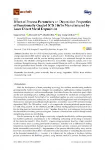
[email protected] II. FORMABILITY AND TENSILE TEST The most commonly used test for predicting metal formability is the uniaxial tension test. Specimens were prepared and test is conducted as per the standard of ASTM standard B-557M which is Standard Test Methods for Tension Testing Wrought and Cast Aluminum- and Magnesium-Alloy Products. Sheet metals possess anisotropy i.e. their properties are dependent of the direction. Hence to find anisotropy; tensile tests were conducted along three different directions, with the tensile axis being parallel (0), diagonal (45) and perpendicular (90) to the rolling direction of sheet. The strain hardening coefficient (n) and strength coefficient (k) of material were determined from the slope of true stress-true strain curve when plotted on logarithmic coordinates. The relation is given by following equation: σ = k en where
(1)
σ: True stress k: Strength coefficient n: Strain hardening coefficient e: Engineering strain
metal forming, formability parameters I. INTRODUCTION Sheet metal is one of the most fundamental forms used in metal working, and can be cut and bent into a variety of shapes. Modern continuous rolling mills produce large quantities of thin sheet metal at low cost. A substantial fraction of all metals are produced as thin hot or cold-rolled sheet; this is then formed in secondary processes into automobiles, domestic appliances, building products, aircraft, food cans and most of other familiar products. Sheet metals parts have the advantage that the material has a high elastic modulus and high yield strength so that the parts produced can have a good strength-to-weight ratio.
Fig 1: Log-Log Plots of True Stress and True Strain
Fig. 2. Theoretical forming limit diagram
Fig. 3. Finite element analysis
Tensile properties, strain hardening coefficient (n) and strength coefficient (k) of material for three different rolling directions are as shown in Table 1.
Using the equations (4) and (5), the major and minor strains are calculated and with those values FLD is plotted. Major strain is fixed on Y axis and minor strain is fixed on X axis.
TABLE I. TENSILE PROPERTIES OF MATERIAL
Direc tion
Yi e l d S tres s MP a
UTS MP a
k Mpa
n
0°
179.87
182.69
498.84
0.13
45°
158.74
167.62
402.84
0.14
90°
187.53
183.69
493.74
0.19
Average
172.40
174.86
449.57
0.15
Xm= (X0+2X45+X90)/4; where X is k and n
III. THEORETICAL PREDICTION OF FORMING LIMIT DIAGRAM Forming limit diagram is needed to predict the behaviour of sheet during forming and to compare the strain development in cup. Theoretical prediction of FLD is made using Levy Mises flow rule for limiting strain. The limiting strains are calculated using Levy-Mises flow rule for plastic deformation in which λ, e1 and e2 are given by:
2(1 rm ) m1
(2)
The values of σ1 and σ2 are calculated by the yield criterion; by putting value of σ1 from 0 to UTS.
( 1 2 ) m (1 2rm )( 1 2 ) 2(1 rm )
m
(3)
e1 = [(1+2rm )(σ1- σ2)m-1+( σ1+ σ2)m -1]
(4)
e2 = [-(1+2rm )(σ1- σ2)m-1+( σ1+ σ2)m -1]
(5)
IV. FINITE ELEMENT ANALYSIS OF SPIF For the finite element analysis of incremental forming; HYPERMESH was used as pre-processor and ABAQUS/Explicit is used as solver and post-processor. The tool is a special part which is defined as analytically rigid sphere as only half of its lower surface came in contact with blank. Sheet blank was defined as continuous and homogeneous shell element 2304 of thickness 0.46 mm. Figure 3.5 shows the part modeling of tool and sheet blank. V. DESIGN OF EXPERIMENTS AND WORK Design of Experiments using Taguchi method is an organized method to yield the maximum desired output with the least number of experimentation and also to determine the factors that influence the output of the experiment. The main objectives of the design of experiments are to minimize the number of trials, to get simultaneous variation in all process parameters, to determine the factor that influences the output most.The experimental runs and responses are as stated in table 2. Table 2. Experimental runs and responses Process Parameters Run Id 1 2 3 4 5 6 7 8
Tool Dia.
Step Size
Feed Rate
8 8 8 10 10 10 12 12
0.5 0.62 0.75 0.5 0.62 0.75 0.5 0.62
300 400 500 400 500 300 500 300
Responses Final Thicknes s 0.26 0.27 0.27 0.25 0.24 0.23 0.24 0.23
Fracture Depth 35 24 18 35 27 16 35 27
9
12
0.75
400
0.23
19
optimum test conditions were estimated from the significant factors. The computed value of Fcal (28.0) was more than that
For conducting an experiment we had a choice of three input parameters which were tool diameter, vertical step size and feed rate. So 3 Factor- 3 Level i.e. L9 model is used which gave 9 experimental runs to be conducted. It was created using MINITAB statistical package. The basic things required to conduct an experiment are sheet metal blank, blank holder, single point forming tool, forming Machinery i.e. CNC Milling Machine. Machine used was make of Lakshmi Machine Works (Model LV45) with FANUC from statistical Ftab (19.0). The last column of the above table Oi MATE MC control system. Fig. 4. Effect of individual factor on average S/N ratio VI. TAGUCHI ANALYSIS AND ANOVA OF FINAL indicates the percentage of contribution (%P) of each factor,
THICKNESS
thus exhibiting the level of influence on the quality To analyse the design of an experiment; observed response characteristics. The Table 4.3 shows tool diameter, steps size of final thickness and signal to noise ratio are calculated and and feed rate have percentage contributions of 84.86, 9.09 represented in Table 3. and 3.04 on the final thickness of sheet blank respectively. Table 3. Analyse the design of an experiment Table 4. ANOVA of final thickness Run Id
Final Thickness (mm) 1 0.26 2 0.27 3 0.27 4 0.25 5 0.24 6 0.23 7 0.24 8 0.23 9 0.23 In order to maximize the
S/N Ratio
Mean of means
Para-
Mean Fcal
meter -11.7005 0.26 -11.3727 0.27 -11.3727 0.27 -12.0412 0.25 -12.3958 0.24 -12.7654 0.23 -12.3958 0.24 -12.7654 0.23 -12.7654 0.23 S/N ratio, the following levels of
Sum of
Ftab
Contri-
squares
squares
0.001867
0.000933
28.0
19.0
84.86
0.000200
0.000100
3.0
19.0
9.09
0.000067
0.000033
1.0
19.0
3.04
Error
0.000067
0.000033
Total
0.002200
bution
Tool Dia. Step Size Feed Rate
factors were used: tool diameter– level 1(8 mm), steps size– level 1 (0.5 mm) and feed rate– level 3(500 mm/min). Fig. 4 shows effect of individual factor on average S/N ratio of final thickness. Examination of the calculated Fisher’s values (F) for all
VII. TAGUCHI ANALYSIS AND ANOVA OF FRACTURE
control factors also showed high influence and low influence
DEPTH
factors on the final thickness as shown in Table 4.3. Fishers’ value was calculated for each process parameters. The
To analyse the design of an experiment; observed response of final thickness and signal to noise ratio are calculated and
represented in Table 5. The estimated individual factor’s effect on mean depth for deformed section of Al alloy sheet is shown in Figure 5.
Results and Discussions The last column of the above table indicates the percentage of contribution (%P) of each factor, thus exhibiting the level
Table 5. Analyse the design of an experiment
of influence on the quality characteristics. The Table 4.3 shows tool diameter, steps size and feed rate have
Run Id 1 2 3 4 5 6 7 8 9
Fracture Depth (mm) 35 24 18 35 27 16 35 27 19
Mean of means
S/N Ratio -11.7005 -11.3727 -11.3727 -12.0412 -12.3958 -12.7654 -12.3958 -12.7654 -12.7654
0.26 0.27 0.27 0.25 0.24 0.23 0.24 0.23 0.23
percentage contributions of 84.86, 9.09 and 3.04 on the final thickness of sheet blank respectively. The last column of the Table 6 indicates the percentage contribution (% P) of each factor, thus exhibiting the level of influence on the quality characteristic. The Table 4.5 shows that the tool diameter, step size and feed rate had a percentage contributions of 0.63, 97.49 and 0.19% on the fracture depth of frustum of a cup respectively. Conclusion
Examination of the calculated Fisher’s values (Fcal) for all control factors also showed a very high influence of step size and low influence of tool diameter and feed rate as shown in
Para-
Sum of
Contri-
Mean Fcal
meter
squares
squares
2.889
0.000933
Ftab bution
Tool 0.42
19.0
0.63
Dia. Step 450.889
0.000100
65.4
19.0
97.49
Size Feed 0.889
0.000033
0.13
19.0
0.19
Rate Error
6.889
Total
461.556
0.000033
Table 4.5. F value was calculated for each design parameters. The optimum test conditions were estimated from the significant factors. The computed value of Fcal (65.45) was more than the statistical Ftab (19.00). Table 6. ANOVA of fracture depth
From Taguchi analysis and ANOVA we can conclude that Vertical step size has a major influence on fracture depth Tool diameter influences the surface finish of the part In conventional forming sheet is under both simple tension and biaxial stretching In SPIF Wall surfaces are under Plane stretching condition and Corner surfaces are under biaxial stretching condition REFERENCES Jeswiet J`., Micari F., “Asymmetric Single Point Incremental Forming of Sheet Metal”, IMECHE Engineering Manufacture, 218, pp. 1-23, 2009. Kim, Y. H., Park, J. J. “Effect of process parameters on formability in incremental forming of sheet metal”, Journal of Materials and Processing technology’’, 130, pp. 42-46, 2002. Iseki, H.; Kato, K., Kumon H., Ozaki, K. “Flexible and Incremental Sheet Metal Bulging Using a Few Spherical Rollers”, JSME, 59, pp. 2849-2854, 2001. Bambach, M., Hirt, G., Ames, J., “Modeling of optimization strategies in the incremental CNC sheet metal forming process”, NUMIFORM, pp. 1969-1974, 2004. Bramley A. N., “Incremental Sheet Forming Processes for Small Batch and Prototype Parts”, Idee-Vision-Innovation, pp. 95-102, 2001. Hirt, G., Ames, J., Bambach, M. A., “New forming strategy to realize parts designed for deep-drawing by incremental CNC sheet forming”, Steel Research, 76, pp 160-166, 2005.