International Journal of Engineering Research Volume No.5, Issue Special 1 pp : 99-105
ISSN:2319-6890(online),2347-5013(print) 8 & 9 Jan 2016
Effect of Soil Structure Interaction for Framed Structure Resting on Multilayered Soil Mass Gaurav D. Dhadse Assistant Professor, G.H. Raisoni College of Engineering and Management, Amravati, India Email :
[email protected] Abstract: In conventional model of the frame structure, the effect of Soil Structure Interaction is neglected considering the support conditions as fixed or pinned. But in order to understand the actual behavior of structure resting on existing soil mass, the effects of Soil Structure Interaction must be taken into consideration. Thus in this paper space frame and multilayered soil mass system is analyzed for gravity load conditions using Finite Element Method with Ansys 11.0 as analysis tool. Also assumed space frame is consisting of columns of different orientation and beams of same sizes. Thus model under consideration is analyses for Non Interaction Analysis(NIA), Interaction Analysis considering soil mass as Elastic(IAE) and Interaction Analysis considering soil mass as Elasto-Plastic (IAEP). The results are correlated for Vertical Displacement and Stresses in Structure due to flexible soil condition. After analyzing, the model for different conditions of SSI effect, it was found that SSI must be taken into consideration while analyzing framed structure. Keywords: Ansys 11.0, Displacement, Finite Element Analysis, SSI, Stress, etc. I. Introduction The framed structures are normally analyzed with their bases considered to be either completely rigid or hinged. However, the foundation resting on deformable soils also undergoes deformation depending on the relative rigidities of the foundation, superstructure and soil. Interactive analysis is, therefore, necessary for the accurate assessment of the response of the superstructure. Also some of researchers also worked on SSI effectiveness which is as follows. Jancy F. et al. (2011) [1] focuses on the computational modeling of ground-structure interaction using finite element package ANSYS and concluded that For multistoried buildings, ground interaction effect on the portal frame behavior may be more significant and hence, the ground structure interaction should be accounted for in the structural analysis of important buildings. Vivek Garg et al. (2012) [2] studied the interaction analysis of a three-bay threestorey RCC space frame- footing-strap beam-soil system is carried out to investigate the interaction behavior using the finite element method and they conclude that there is significant redistribution of end moments in structure. Pallavi Ravishankar B. et al. (2013) [3], focused on asymmetrical high rise building modelled along with the homogenous sandy soil strata and analysis is carried out giving result that for the same soil strata displacements and stresses in case of pile foundation system is comparatively less than raft foundation system. Jenifer Priyanka R. M. et al. (2012) [4], attempted the effect of Soil-structure interaction on multi storeyed buildings with various foundation systems and came to conclusion that Lateral deflection, Storey
NCICE@2016
drift, Base shear and Moment values of fixed base building was found to be lower as compared to flexible base building. Hence suitable foundation system considering the effect of Soil stiffness has to be adopted while designing building frames for seismic forces. Kadam K. N. et al. (2013) [5], studied the influence of pile length configurations on behavior of multistoried are evaluated under vertical loading and observes that the optimum configuration of pile is soil dependent. The best configuration varies from soil-to-soil. Raksha J. Khare et al. (2013) [6], examines the effect of soil-structure interaction on a four storeyed frame (G+3), two-bay frame resting on pile group embedded in the cohesive soil and observed that Displacement is less for the fixed condition and increases when SSI is taken into account. All the available literatures give insight about Soil Structure Interaction analysis for various conditions. Basically every researcher tries to shows the difference between non SSI analysis and SSI analysis. In static SSI researchers prove that there is increase in displacement of structure, moment and shear force in member after considering SSI. Thus all researchers have given their best but about 90% of them did work only considering linear soil conditions and single layered soil mass. About 60% of them only show difference between SSI and non SSI analysis without giving clear view of parameter to be considered while designing i.e. variation of moments, steel etc. Thus in this paper a multilayered soil mass is considered for analyzing the effect of SSI on framed structure for linear and non linear soil properties. II. Idealization of Structure and Soil In present problem a 3 bay x 3 storey RCC space frame resting on multilayered soil mass and subjected to gravity loading is analyzed. The problem under consideration is symmetric about both axes in terms of geometry, material properties and loading. The superstructure of proposed model is depicted in Figure 2.1.
doi : 10.17950/ijer/v5i1/022
Page 99
International Journal of Engineering Research Volume No.5, Issue Special 1 pp : 99-105
ISSN:2319-6890(online),2347-5013(print) 8 & 9 Jan 2016 The geometric and material properties of proposed model are given in Table 2.2 Table 2.2: Geometric and material properties of frame, footing and soil mass COMPONENT
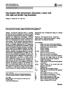
Fig. 2.1: Plan showing columns and footings
Frame
The geometric and material properties of proposed model are given in Table 2.2. And elevation of Frame 1, Frame 2, Frame 3, Frame 4 and plan of all beams are shown in figure 2.2 (a), 2.2(b) and 2.2(c), 2.2(d) respectively.
Frame
Isolated Footing
(a)
(b) Concrete
Soil Mass
(c) (d) Fig. 2.2: (a) elevation of Frame 1 & 4 (b) Frame 2 & 3 (c) Plan showing Ground beams & plinth beams (d) Plan showing slab beams for first, second and terrace floor This model approaches towards practical situation; a site where multilayered soil is available. Thus in this model three layer soil is used with increasing stiffness from top layer. The thickness of each layer is calculated from shear wave velocity criteria as explain in Eurocode 8 [7]. And width of soil mass decided from trial and error analysis and which equals to 60m considering depth of soil mass constant as 58.34m (from shear wave velocity). Following Table 2.1 shows the soil type with depth for the proposed model. Table 2.1: Types of Soil with Depth Soil Type (Layers) Depth (m) Firm Clay or Hard Medium Clay or 13.65 Stiff Clay Silty Sand 27.20 Dense Sand and Gravel 17.49
NCICE@2016
First layer (Firm Clays or Stiff Clays or Medium hard clay)
Second Layer (Silty Sand)
Third Layer
doi : 10.17950/ijer/v5i1/022
DESCRIPTION
DATA
Number of storeys
3
Number of bays in X direction
3
Number of bays in Y direction
3
Floor to floor height
3.0 m
Plinth height
1.0 m
Bay width in X direction
4.0 m
Bay width in Y direction
4.0 m
Beam dimensions
(0.23 x 0.3) m
Columns C1,C13,C4,C16(A)
(0.23 x 0.3) m
Columns C2,C14,C3,C15,C5,C9,C8,C12(B)
(0.38 x 0.23) m
Columns C6,C10,C7,C11(C)
(0.23 x 0.45) m
Thickness of all slabs
0.15 m
Footing under Columns C1,C13,C4,C16(F1)
1.5m x 1.5m x 0.35m
Footing under Columns C2,C14,C3,C15,C5,C9,C8,C12(F2)
1.8m x 1.8m x 0.4m
Footing under Columns C6,C10,C7,C11(F3)
2.2m x 2.2m x 0.5m
Modulus of elasticity of concrete for(M20)
22360 x 106 N/m2
Poisson’s ratio of concrete
0.15
Density of RCC
2500 kg/m3
Acceleration due to gravity (g)
9.81 m/s2
Total Extent
60.0 m x 58.34 m
Depth
13.65 m
Modulus of elasticity of soil
100 x 106 N/m2
Poisson’s ratio of soil
0.3
Safe Bearing Capacity (SBC)
200 kN/m2
Density
2000 kg/m3
Cohesion
50 x 103 N/m2
Frictional angle
190
Shear Modulus (G)*
6900-34500 kPa
Shear wave velocity (Average)*
290 m/s
Depth
27.20 m
Modulus of elasticity of soil
120 x 106 N/m2
Poisson’s ratio of soil
0.25
Safe Bearing Capacity (SBC)
300 kN/m2
Density
2070 kg/m3
Cohesion
30 x 103 N/m2
Frictional angle
210
Shear Modulus (G)* Shear wave velocity (Average)*
27600-138000 kPa 290 m/s
Depth
17.49 m
Page 100
International Journal of Engineering Research Volume No.5, Issue Special 1 pp : 99-105 (Dense Sand and Gravel)
Modulus of elasticity of soil
170 x 106 N/m2
Poisson’s ratio of soil
0.2
Safe Bearing Capacity (SBC)
500 kN/m2
Density
2250 kg/m3
Cohesion
20 x 103 N/m2
Frictional angle
250
Shear Modulus (G)*
69000-345000 kPa 700 m/s
Shear wave velocity (Average)*
ISSN:2319-6890(online),2347-5013(print) 8 & 9 Jan 2016 Terrace floor Outer slab beams Inner slab beams
22900 38900
2.2 Finite Element Modeling The interaction analysis of the problem is carried out using ANSYS software (Version 11). The finite element discretization of the problem is shown in Figure 2.3
(*= Source: Indo-Norwegian Training Programme New Delhi, 26–28 May 2014; Seismic Design of Multi-Storey Buildings: IS 1893 vs. Eurocode 8; Dominik H. Lang, Dr.‐Ing. Dr.philos. Senior Researcher, Project Manager NORSAR, Kjeller.) To investigate the interaction behavior, the interaction analyses are carried out for the following three cases considering all frames of structure as plane frame. Case-1: The conventional non-interaction analysis (NIA) considering the columns fixed at their bases. Case-2: The interaction analysis of plane frame isolated footingsoil system considering the columns supported on individual column footings and resting on soil media (Elastic Analysis). (IAE) Case-3: The interaction analysis of plane frame isolated footingsoil system considering the columns supported on individual column footings and resting on soil media (Elasto-plastic Analysis). (IAEP) where, NIA - Non-Interaction Analysis IAE - Interaction Analysis Elastic IAEP - Interaction Analysis Elasto-Plastic The frame, foundation and supporting soil mass are considered to be elastic in IAE and in IAEP soil mass are considered as elasto-plastic, to act as a single compatible structural unit for more realistic analysis. 2.1 Loads Loads are calculated by usual way i.e. for slab, Live Load = 3kN/m2, Floor Finish = 1.25 kN/m2, and after this factored it and distributed on beams as per IS 456-2000 [8]. For beams, the loads of walls are calculated and factored it. As far as dead load is concerned, Ansys’11 calculated dead weight of members from mass density and acceleration due to gravity hence these properties are required while assigning. Following Table 2.3 shows factored UDL intensities on all beams [8]. Table 2.3: Factored UDL Intensities on Beams U.D.L. Structural INTENSITIES Component (N/m) Ground Beams 25530 Plinth beams 9315 First and Second floor 34630 Outer slab beams 41315 Inner slab beams
NCICE@2016
Figure 2.3: Finite element discretization of frame-footing-soil system The frame structure, footing and soil mass is discretized with 8 noded plane stress element (PLANE 82) for NIA, IAE and IAEP with two degree of freedom per node (Ux and Uy). It is assumed that the joints between various members are perfectly rigid. The vertical displacements in soil mass are restrained at the bottom boundary whereas horizontal displacements are restrained at vertical boundaries. For Case 3, elastic-plastic behavior of the ground is modeled using Drucker-Prager criterion in ANSYS’11. The input consists of only three constants: The cohesion value (must be > 0) The angle of internal friction The dilatancy angle. The interface characteristics between the isolated footing and soil are represented by TARGE169 and CONTA172 elements in same way interface between two soil layers are also modeled with TARGE169 and CONTA172 elements. The element size for frame and footings are taken as 0.1m x 0.1m. The soil mass is discretized with 1m x 1m finer meshes in close vicinity of footing where stresses are of higher order [9]. III. Interaction Analysis (Displacements) Considering all above information, interaction analysis is done for displacements and stresses and results are discussed in this section. The vertical displacements in the frame and footings due to NIA, IAE and IAEP discussed subsequently. Figure 3.1, 3.2, 3.3, 3.4 shows the displacement results of Frame 1, Frame 2, Frame 3 and Frame 4 for NIA, IAE and IAEP respectively.
doi : 10.17950/ijer/v5i1/022
Page 101
International Journal of Engineering Research Volume No.5, Issue Special 1 pp : 99-105
ISSN:2319-6890(online),2347-5013(print) 8 & 9 Jan 2016
Fig. 3.3: Vertical Displacement of Frame 3 for a. NIA b. IAE c. IAEP
Fig. 3.1: Vertical Displacement of Frame 1 for a. NIA b. IAE c. IAEP
Fig. 3.4: Vertical Displacement of Frame 4 for a. NIA b. IAE c. IAEP
Fig. 3.2: Vertical Displacement of Frame 2 for a. NIA b. IAE c. IAEP
NCICE@2016
From the above figures, it is observed that increase in soil stiffness reduced the vertical displacement drastically, if more realistic approach is used and whole soil over bed rock is considered in modeling then the most feasible results are found and therefore this must be the reason of increased vertical displacement. The variation of vertical displacement for various analyses is shown in following bar charts in Figure 3.5.
doi : 10.17950/ijer/v5i1/022
Page 102
International Journal of Engineering Research Volume No.5, Issue Special 1 pp : 99-105
DISPLACEMENT IN MM NIA
IAE
IAEP 127.2
38.41 2.2
ISSN:2319-6890(online),2347-5013(print) 8 & 9 Jan 2016 From above bar charts it is clear that vertical displacement goes on increasing from NIA to IAE and IAE to IAEP. Thus all the analysis cases are important. If we compare the allowable settlement of footing with the given results then as per IS 1904-1986 allowable settlement for isolated footing is limited to 50 mm [10] and results shows maximum vertical displacement of footing 113.06 mm. Here the maximum vertical displacement value is more than allowable after considering more realistic approach the model become unsafe hence soil structure interaction effect is important.
GROUND FLOOR BEAM
The stress intensities in beams columns and footings due to NIA, IAE and IAEP discussed subsequently. Following bar charts in figure 4.1, 4.2 and 4.3 shows the exact behavior of stresses in NIA, IAE and IAEP respectively.
DISPLACEMENT IN MM NIA
IAE
IV. Interaction Analysis (Stresses)
IAEP 127.2
38.41 4.5 FIRST FLOOR BEAM
DISPLACEMENT IN MM NIA
IAE
IAEP 127.2
38.41 4.5 SECOND FLOOR BEAM
DISPLACEMENT IN MM NIA
IAE
IAEP 127.2
38.41 5.12 TERRACE FLOOR BEAM Fig. 3.5: Comparison of Vertical Displacement in beams for NIA, IAE & IAEP
NCICE@2016
doi : 10.17950/ijer/v5i1/022
Page 103
International Journal of Engineering Research Volume No.5, Issue Special 1 pp : 99-105
ISSN:2319-6890(online),2347-5013(print) 8 & 9 Jan 2016
Fig. 4.1: Comparison of stresses in Beam
Fig. 4.3: Comparison of stresses in Footings As far as stress intensities due to bending and settlement are concern, stresses are increasing rapidly from NIA to IAE but slight change for IAEP. In IAE displacement is due to deflection and settlement both but in IAEP displacement is due to settlement only as soil is plastic also soil shows nearly perfect plastic behavior in IAEP. Hence stresses are nearly same for IAE and IAEP. Stress analysis shows, only displacement increases in IAEP but stress intensity due to bending and settlement remains approximately same in IAE and IAEP. “Therefore displacements in IAEP and stresses in IAE are important from design consideration”. Second and fourth frame (both inner frames) shows increased vertical displacement. Hence it is confirmed that depth of soil mass above the bed rock must be consider to get most exact behavoiur. V. Conclusions 1. Fig. 4.2: Comparison of stresses in Columns
2.
3. 4.
5.
6.
NCICE@2016
From the analysis, it can be concluded that stresses in IAE and vertical displacement in IAEP are important from design consideration. Also second and fourth frame (both inner frames) shows maximum vertical displacement as total load act towards the C.G. of structure thus due to flexible support condition, soil stiffness reduced and displacement increased. Vertical displacement of higher storey beams is found more than lower story beams after considering SSI analysis. Because of more realistic approach is used, it is confirmed that whole depth of soil mass above the bed rock and proper width from trial and error analysis must be consider while modeling to get most exact behavoiur. Also plastic behaviour of soil by stress analysis and increased vertical displacement by displacement analysis can be used in design of structure. Basic reason of finding out stress is that, while finding end moments there is no need to do IAEP analysis hence it saves
doi : 10.17950/ijer/v5i1/022
Page 104
International Journal of Engineering Research Volume No.5, Issue Special 1 pp : 99-105 computer memory. Also soil plasticity can be best viewed by stress analysis only. 7. This model shows maximum vertical displacement of about 127.2 mm for beams in frame and 113.06 mm for footings but the permissible value for footing displacement is 50mm as per IS 1904-1986 thus footing fail in this model. 8. Variation of displacement in beams shows different pattern, as in NIA supports are fixed hence maximum displacement found at mid section of beam but after considering flexible supporting foundation, middle supports are also sink hence displacement of whole structure is like saucer. 9. In stress analysis, NIA shows maximum stress at junction but in IAE Stress at middle junctions reduces due to sinking and increases at outer junctions. Hence there is redistribution of stress is found. Also this stress is due to bending and settlement hence there must be redistribution of end moment found. 10. As from the stress analysis, the stresses just below the footings are so high that soil fails its strength and that is the basic reason of increasing the vertical displacement. 11. Therefore both the stress and displacement are out of limit after considering actual stiffness hence while designing, in addition to SBC, the stiffness of soil mass must be considered.
ISSN:2319-6890(online),2347-5013(print) 8 & 9 Jan 2016 References i.
ii.
iii.
iv.
v.
vi.
vii.
viii. ix. x.
NCICE@2016
F. Jancy, A. Rajagopal, B. Umashankar, M. R. Madhav, (2011) ‘Finite Element Modeling of Ground - Structure Interaction Considering NonLinear Response of the Ground’, Proceedings of Indian Geotechnical Conference Kochi (Paper No.N-281). Vivek Garg and M.S. Hora , (2012)‘Interaction Effect of Space Frame-Strap Footing-Soil System on Forces in Superstructure’, ARPN Journal of Engineering and Applied Sciences, ISSN 1819-6608, VOL. 7, NO. 11. Pallavi Ravishankar, Dr D Neelima Satyam, (2013) ‘Numerical Modelling To Study Soil Structure Interaction For Tall Asymetrical Building’, International Conference on Earthquake Geotechnical Engineering Istanbul, Turkey, Report No: IIIT/TR/2013/-1. R. M. Jenifer Priyanka, N. Anand , Dr. S. Justin, (2012) ‘Studies on Soil Structure Interaction of Multi Storeyed Buildings with Rigid and Flexible Foundation’, International Journal of Emerging Technology and Advanced Engineering, ISSN 2250-2459, Volume 2, Issue 12. R. R. Chaudhari, Dr K. N. Kadam, (2013) ‘Effect Of Piled Raft Design On High-Rise Building Considering Soil Structure Interaction’, International Journal Of Scientific & Technology Research, ISSN 2277-8616, Volume 2, Issue 6. Raksha J. Khare, H.S.Chore, (2013) ‘Interaction of Building Frame with Pile’, International Journal of Electrical, Electronics and Computer Systems (IJEECS), ISSN (Online): 2347-2820, Volume-1, Issue -1. Eurocode 8, (2004) ‘Design of structures for earthquake resistance - Part 1: General rules, seismic actions and rules for buildings’, Supersedes ENV 1998-1-1:1994, ENV 1998-1-2:1994, ENV 1998-1-3:1995, (ICS 91.120.25). IS 456 – 2000, ‘Indian standard Criteria for Plain and Reinforce Structure’, ICS 91.100.30 New Delhi. C. S. Krishnamoorty, (2010) ‘Finite Element Analysis’, 2nd edition, Mc Graw Hill, New Dehli. IS 1904 – 1986, ‘Indian standard Code of Practice for Design and Construction of Foundations in Soils: General Requirements’, (UDC 624’15’04: 006’76 New Delhi).
doi : 10.17950/ijer/v5i1/022
Page 105