Journal of Mechanical Science and Technology 27 (4) (2013) 1053~1061 www.springerlink.com/content/1738-494x
DOI 10.1007/s12206-013-0228-2
Effects of geometric parameters on static load capacity of a double-row four-point contact ball bearing† Guanci Chen1,*, Ping Jia2 and Jianqiang He3 1
Faculty of Mechanical and Electrical Engineering, Kunming University of Science and Technology, Kunming, 650093, China 2 School of Mechanical Engineering, Dalian University of Technology, Dalian 116024, China 3 College of Water Resources and Architectural Engineering, Northwest A&F University, Yangling, Shaanxi Province, 712100, China (Manuscript Received April 4, 2012; Revised October 14, 2012; Accepted October 14, 2012) ----------------------------------------------------------------------------------------------------------------------------------------------------------------------------------------------------------------------------------------------------------------------------------------------
Abstract The geometric parameters, which are difficult to design because of the lack of a corresponding theory and tool, of a double-row fourpoint contact ball bearing, determine its carrying capacity. In this study, a mechanical model (nonlinear algebraic equations) with the effect of the row spacing, which is different from the current theory for a single-row ball bearing, has been developed. Also, using the corresponding calculation procedure programmed by MATLAB, the effects of the geometric parameters on the load capacity of the bearing have been studied. Some design suggestions have been made for the bearing geometric parameters: to improve the contact strength between the ball and raceway, the row spacing should be designed as small as possible if the bending strength of the mid beam among the rows is enough. To avoid more interference force, the negative clearance should be near zero. Keywords: Double-row four-point contact ball bearing; Geometric parameter; Load capacity; Mechanical model; Row spacing ----------------------------------------------------------------------------------------------------------------------------------------------------------------------------------------------------------------------------------------------------------------------------------------------
1. Introduction A double-row four-point contact ball bearing is a type of bearing used to carry combined loads (force and moment). Its carrying capacity is determined by the bearing geometric parameters and material. For valid design and application of the bearing, it is very necessary to find the effects of the geometric parameters on the load capacity in a double-row four-point contact ball bearing. Zupan and Prebil [1] established a computation model for calculating carrying angle and carrying capacity of a large single-row ball bearing as function of geometry parameters of the rolling contact and the supporting structure stiffness. Their results confirmed the theoretical cosine-based contact load distribution for rigid supporting structures. Amasorrain et al. [2] discussed a calculation procedure, which was an extension to four contact-point of the general bearing theory, for determining the load distributions in the rolling elements of a four contact-point slewing bearing with one row of ball bearings, under general load conditions (moment, axial load and radial load). Olave et al. [3] proposed a procedure for obtaining the load distribution in a four contact-point slewing bearing considering the effect of the structural elasticity. At the same time, *
Corresponding author. Tel.: +86 087165933056, Fax.: +86 087165933056 E-mail address:
[email protected] † Recommended by Associate Editor Chang-Wan Kim © KSME & Springer 2013
they created a finite element model (FEM) for the global model, which represented the rolling elements and their contact with the raceways. Results obtained using the FEM have been correlated with the results of the new procedure. Daidié et al. [4] presented a 3D finite element simplified analysis of load distribution and contact angle variation in a slewing ball bearing. The key element of their methodology was modeling the rolling elements under compression by nonlinear traction springs between the centers of curvature of the raceways. Although the methodology was valid, the modeling procedure, which had to be redone when the bearing and its supporting structure was changed, was tedious because of too many contact pairs between balls and raceways. Kania [5] analyzed a complete slewing bearing by substituting the rolling elements for truss elements in the FE model. Truss elements had the nonlinear elastic material properties obtained by modeling the load-deformation characteristics in the roller and raceway contact zone. Kania advised about the difficulty of modeling the full bearing model by taking the rolling elements and the contact areas into account. Smolnicki [6] presented a superelement-based discrete bearing model, with which all factors involved in the bearing-supporting structures system were taken into account. Smolnicki [7] described the application of the finite element method for obtaining load distribution in the superstructure rotation joint of single-bucket caterpillar excavators, which consisted of a torque slewing bearing. Potočnik
1054
G. Chen et al. / Journal of Mechanical Science and Technology 27 (4) (2013) 1053~1061
et al. [8] studied fatigue life of double-row slewing ball bearing with irregular geometry. They described a computational procedure consisting of calculation of the maximum contact force on the rolling element, where the geometry of the bearing was described with vectors, which enabled modeling of irregular shapes of the bearing rings. Researchers above have provided some calculation procedures or FE methodology for load and deformation analysis of single-row ball bearings. These calculation procedures are not suitable for a double-row four-point contact ball bearing any more. Furthermore, although FE methodology is also a valid way for analyzing load distribution in a double-row four-point contact ball bearing, the modeling procedure is tedious. Once the parameters of the bearing or its supporting structure has been changed, repetitive work has to be done. In this study, the mechanical model and calculation procedure with the effect of the row spacing, which are different from the current theory for a single-row ball bearing, for load capacity analysis of a double-row four-point contact ball bearing has been developed. Also, the effects of the bearing geometric parameters on the load capacity are studied. Some design suggestions of the bearing geometric parameters are made.
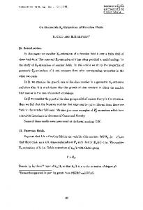
Fig. 1. Sectional view of a double-row four-point contact ball bearing.
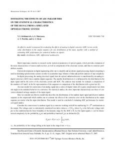
Fig. 2. Loads in the inner ring.
2. Theory basis 2.1 Geometric model Fig. 1 shows the axial section π of a double-row four-point contact ball bearing. The z-axis is the axial direction of the bearing. The r-axis is the radial direction of the bearing. The centers of the inner ring and outer ring are coincident. There are four raceway arcs in each row. Here, "inner upper" raceway is defined as the upper raceway arc of the inner ring. "Inner lower" raceway is defined as the lower raceway arc of the inner ring. In like manner, "outer upper" raceway is defined as the upper raceway arc of the outer ring; "outer lower" raceway is defined as the lower raceway arc of the outer ring. Dpw is the pitch circle diameter. Dw is the ball diameter. The bearing is with a nominal contact angle α0. The clearance between the ball and the bearing ring is C0. The distance of the centers of the balls is a0 called row spacing. The "inner upper" and "inner lower" raceways have the same radius Ri , and the "outer upper" and "outer lower" raceways have the same radius Ro. The raceway arc center does not coincide with the ball center. There is a distance d, in which the projection length on the raxis or z-axis is l, among them. Fig. 2 shows the loads and displacements on the inner ring of a double-row four-point contact ball bearing. A fixed Cartesian coordinate system is set up at the bearing center O. Thus, the x-axis and y-axis are the radial direction of the bearing. The z-axis is the axial direction of the bearing and upward. As an example, only two balls at the azimuth angle φ are given in Fig. 2. The r-axis is in the axial section π passing through the balls’ centers at the azimuth angle φ, which is the intersection angle between x-axis and r-axis. The centers circle of the balls in the first row is shown as the top centerline ellipse. The bear-
(a)
(b)
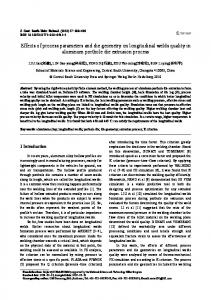
Fig. 3. Contact deformations: (a) and plays; (b) on the balls in the bearing.
ing pitch circle is displayed as the mid centerline ellipse. The center circle of the balls in the second row is shown as the bottom centerline ellipse. The outer ring is fixed; however, the inner ring is free. The inner ring is loaded with moments ( Mx, My, Mz ) and forces ( Fx, Fy, Fz ). Mz is a useful moment to make the bearing rotate. So the moment Mz is not regarded any more in this study. Linear and angular displacements (u, v, w, Φx, Φy) are generated on the inner ring. Raceways of the inner ring probably contact the balls with the elastic contact deformations. The contact forces are Q1, Q2, Q3, Q4 corresponding with the contact angles α1, α2, α3, α4, respectively. To describe the elastic contact deformations and contact forces in the bearing well, local contact deformations and plays on the balls are shown in Fig. 3. When the balls are
G. Chen et al. / Journal of Mechanical Science and Technology 27 (4) (2013) 1053~1061
loaded because of the linear and angular displacements (u, v, w, Φx, Φy) of the inner ring, the contact deformations and forces are generated between the balls and raceways. As an example, Fig. 3 shows the contact deformations and play on the two balls at the plane π. In the first row, the ball contacts the "inner upper" and "outer lower" raceway with the contact force Q1. Because static load performances of the bearing are studied, the centers of the ball and raceways are assumed to be collinear. Thus, the contact force Q1 passes through the ball center. ∆1 is the distance among the centers of the "inner upper" and "outer lower" raceway. ∆2 is the distance among the centers of the "inner lower" raceway and "outer upper" raceway. δ1 is the total contact deformation between the ball and inner raceway, outer raceway. α1 and α2 are the contact angles corresponding with Fig. 2. In like manner, in the second row, the ball contacts the "inner upper" raceway and "outer lower" raceway with the contact force Q3. The total contact deformation is δ3. ∆3 is the distance among the centers of the "inner upper" raceway and "outer lower" raceway. ∆4 is the distance among the centers of the "inner lower" raceway and "outer upper" raceway. The contact angles are α3 and α4 corresponding with Fig. 2. 2.1.1 Bearing initial state (without external loads) When the bearing is not loaded, the centers and axes of the inner ring and outer ring are coincident. The balls are equally spaced on the bearing pitch circle (Fig. 1). The distance d among the centers of the ball and raceways can be calculated by Eq. (1). The projection lengths l of the distance d on the raxis and z-axis are gotten by Eqs. (2) and (3), respectively. Dw − C0 2 = d m cos α 0
d m = Rm −
(1)
l jmr
(2)
l jmz = d m sin α 0
(4)
a0
2
+ l jmz
− l jmz
2
(7)
where the plus is for the raceway in the first row, the minus is for the raceway in the second row. 2.1.2 Bearing final state (under external loads) When the inner ring is loaded, linear and angular displacements (u, v, w, Φx, Φy) are generated on the inner ring (Fig. 2). Because the centers of the inner raceway are shifted with the ring, so the centers of the inner raceway are also shifted by u, v, w, Φx, Φy. However, the outer ring is fixed in the space. Thus, the shift of the centers of the inner raceway can be described with a geometric transformation, which is given by Eq. (8). The coordinates ( xi , yi , zi ) are in the fixed Cartesian coordinate system. xi cos Φ y sin Φ x sin Φ y cos Φ x sin Φ y u x i cos Φ x − sin Φ x v yi yi 0 = zi − sin Φ y cos Φ y sin Φ x cos Φ x cos Φ y w zi 1 1 0 0 1 0
(8)
where the subscript i denotes the inner raceway. Because the angular displacements are very small, Eq. (8) can be simplified as following: Φ xΦ y Φ y u xi 1 x i 1 − Φ x v yi yi 0 . = z zi −Φ y Φ x 1 w i 1 1 0 0 1 0
(9)
To facilitate the analysis, the positions of the raceway centers are described in the cylindrical coordinate system. For the inner raceway, the coordinate (r, φ, z) can be gotten by Eqs. (10) and (11). For the outer raceway, the coordinate (r, φ, z) can be gotten by Eqs. (12) and (13). 2
ri = xi + y i
2
(10)
zi = zi , ro = x + y 2 o
(11) 2 o
(12)
zo = zo
(5)
where the subscript l denotes the lower raceway, the subscript u denotes the upper raceway, the plus is for the inner raceway, the minus is for the outer raceway. z jml = ±
a0
(3)
where α0 is the nominal contact angle, the subscript j is the row number (1-the first row, 2-the second row), the subscript m is raceway number of a bearing (i-the inner raceway, o-the outer raceway), the subscript r denotes the direction of the raxis, the subscript z denotes the axial direction. The coordinates (x, y, z) of the raceway centers can be determined by Eqs. (4)-(7). D x jml = x jmu = pw ± l jmr cos ϕ 2 Dpw ± l jmr sin ϕ y jml = y jmu = 2
z jmu = ±
1055
(6)
(13)
where the subscript o denotes the outer raceway. Therefore, the distances ∆ among the centers of the raceways are calculated by Eqs. (14)-(17). ∆1 =
( r1iu − r1ol )
∆2 =
( r1il − r1ou )
2
2
+ ( z1iu − z1ol )
2
+ ( z1il − z1ou )
2
(14) (15)
1056
G. Chen et al. / Journal of Mechanical Science and Technology 27 (4) (2013) 1053~1061
∆3 =
( r2iu − r2ol )
∆4 =
( r2il − r2ou )
2
+ ( z2iu − z2 ol )
2
2
(16)
+ ( z2 il − z2 ou ) . 2
(17)
The contact deformations δ are calculated by Eqs. (18)-(21). (18) (19) (20) (21)
When δ ≤ 0, there are no contact deformations and forces between the ball and raceways. However, when δ > 0, there are contact deformations and forces between the ball and raceways. Also, the contact angles α can be calculated by Eqs. (22)-(25).
cos α 2 =
Value
Name Ball diameter Dw (m)
0.06
Bearing pitch diameter Dpw (m)
2.451
Groove curvature coefficient (R/Dw)
0.53
o
δ1 = Dw − ( Ri + Ro − ∆1 ) δ 2 = Dw − ( Ri + Ro − ∆ 2 ) δ 3 = Dw − ( Ri + Ro − ∆3 ) δ 4 = Dw − ( Ri + Ro − ∆ 4 )
cos α1 =
Table 1. Basic geometric parameters of the bearing.
( r1iu − r1ol )
(22)
∆1
( r1il − r1ou )
Nominal contact angle α0 ( )
45
Row number
2
Ball number
2×10⁸
Axial clearance (m)
0.0003
Row spacing a0 (m)
0.1
Table 2. Extreme loads of the pitch bearing. Name
Value
Mx (N.m)
-8326000
My (N.m)
3979000
Fx (N)
-234000
Fy (N)
339000
Fz (N)
991000
(23)
∆2
(r − r ) cos α 3 = 2 iu 2 ol ∆3
(24)
f1 = Fx − ∑ ( Q1 cos α1 + Q2 cos α 2 + Q3 cos α 3 + Q4 cos α 4 ) cos ϕ = 0
(25)
f 2 = Fy − ∑ ( Q1 cos α1 + Q2 cos α 2 + Q3 cos α 3 + Q4 cos α 4 ) sin ϕ = 0
(27)
(r − r ) cos α 4 = 2il 2 ou . ∆4
(28)
f 3 = Fz + ∑ ( Q1 sin α1 − Q2 sin α 2 + Q3 sin α 3 − Q4 sin α 4 ) = 0
(29) 2.2 Mechanical model When the contact deformations δ are calculated by Eqs. (18)-(21), the contact force can be calculated by Eq. (26) [9].
f5 = M y − ∑ ( Q1 sin α1 − Q2 sin α 2 + Q3 sin α 3 − Q4 sin α 4 )
D pw
sin ϕ 2 a + ∑ ( Q1 cos α1 + Q2 cos α 2 − Q3 cos α 3 − Q4 cos α 4 ) 0 sin ϕ = 0 2
(30)
Q = Kδ 3/ 2
where
f 4 = M x + ∑ ( Q1 sin α1 − Q2 sin α 2 + Q3 sin α 3 − Q4 sin α 4 )
Dpw
(26)
K = 6.7989 × 10⁹ ∑ ρ −1/ 2 (δ * )
-3/ 2
for steel ball-steel
cos ϕ 2 a − ∑ ( Q1 cos α1 + Q2 cos α 2 − Q3 cos α 3 − Q4 cos α 4 ) 0 cos ϕ = 0. 2
raceway contact; δ is the total contact deformation; Q is the contact force;
∑ρ
(31)
is the principal curvature sum; δ is *
the dimensionless contact deformation.
3. Basic bearing geometric parameters
In Fig. 2, the total forces and moments on the inner ring are in equilibrium. The force equilibrium equations along x-, y-, zaxes are Eqs. (27)-(29). The moment equilibrium equations along x-, y-axes are Eqs. (30) and (31). Because Mz make the bearing rotate, so the moment equilibrium along z-axis is not regarded here. In these equations, the contact forces Q and the contact angles α are the functions of the unknown variables u, v, w, Φx, Φy. The equilibrium equations number equals that of the unknown variables. So the variables u, v, w, Φx, Φy are unique. Because Eqs. (27)-(31) are highly nonlinear, the variables u, v, w, Φx, Φy can be determined by Newton-Raphson method. Furthermore, the contact forces Q and the contact angles α can be calculated by the equations mentioned above.
We studied the effects of the bearing geometric parameters on the load capacity in a double-row four contact-points ball bearing. The basis geometric parameters of the bearing are shown in Table 1. Thus, only the axial clearance is given. The radial clearance is assumed to equal the axial clearance. Also, the clearance C0 in Fig. 1 can be calculated. The materials of the rings and balls are bearing steel. Table 2 shows the extreme loads acted on the inner ring. The moment Mz is not given. 4. Load distribution in bearing Fig. 4 shows the contact forces in the bearing. At the azi-
1057
G. Chen et al. / Journal of Mechanical Science and Technology 27 (4) (2013) 1053~1061
250
Contact angle α 1 in the first row
Contact force Q2 in the first row
90
Contact force Q3 in the second row
80
Contact angle α 3 in the second row
70
Contact angle α 4 in the second row
Contact force Q4 in the second row
100
Contact angle α 2 in the first row
o
150
Contact angle α ( )
Contact force Q (kN)
200
100
Contact force Q1 in the first row
50
60 50 40 30 20 10
0 -30 0 30 60 90 120 150 180 210 240 270 300 330 360 390 o Azimuth angle φ ( )
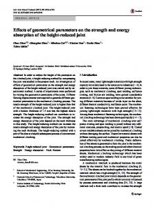
muth angle 26.67o~110o, the contact forces Q1 are greater than zero (maximum 164.1 kN at the azimuth angle 70o), which means the balls contact the "inner upper" raceway and "outer lower" raceway. At the azimuth angle 30o~106.67o, the contact forces Q3 are positive (maximum 122.1 kN at the azimuth angle 70o). Q1 is greater than Q3 at the same azimuth angle. At the azimuth angle 196.67o~283.33o about 180o more than the Q1 position, the contact forces Q2 are positive (maximum 138.2 kN at the azimuth angle 240o). At the azimuth angle 193.33o~286.67o, the contact forces Q4 are generated (maximum 171.34 kN at the azimuth angle 240o ). Q2 is a little less than Q4 at the same azimuth angle. The distribution of Q1 and Q4 is similar. Also, the distribution of Q2 and Q3 is similar. There are no contact deformations and forces between the balls and raceways at the other azimuth angle of the bearing. Q1 and Q4 which are apart from about 180o constitute a moment. Also, Q2 and Q3 which are also apart from about 180o constitutes another moment. These two moments balance the external loads. Thus, most of the external loads are carried by both the raceways (Q1 and Q4). The maximum contact force (Q4 = 171.34 kN) of the bearing is in the second row. Fig. 5 shows the corresponding contact angles. Although the maximum contact angle (65.65o) is 14.72o more than the minimum one (50.93o) in the bearing, there are little differences among the contact angles at the same azimuth angle. Corresponding with Q1 and Q3, the maximum difference of the contact angles at the same azimuth angle is 1.45o. Also, corresponding with Q2 and Q4, the maximum difference of the contact angles at the same azimuth angle is 1.57o. The contact angles where there are no contact forces are zero in Fig. 5.
5. Effects of bearing geometric parameters on load capacity 5.1 Roles of row spacing Fig. 6 shows the effects of the row spacing on the maxi-
o
Azimuth angle φ ( )
Fig. 5. Contact angle distribution in the bearing.
180
Maximum contact force Qmax (kN)
Fig. 4. Contact force distribution in the bearing.
0 -30 0 30 60 90 120 150 180 210 240 270 300 330 360 390
170 160
Maximum Q1 in the first row Maximum Q2 in the first row
150
Maximum Q3 in the second row Maximum Q4 in the second row
140 130 120 110 60
70
80
90
100 110 120 130 140 150 160 Row spacing a0 (mm)
Fig. 6. Effects of the row spacing on the maximum contact force.
mum contact force in the bearing. The maximum Q1 and Q4 add (added value 15.42 kN) with the increase of row spacing because the loads concentrate on the part of balls that are far from the moment axis. On the contrary, the maximum Q2 and Q3 reduce (reducing value 17.78 kN) with the increase of the row spacing. It indicates that the larger the row spacing is, the more loads concentrate on the minority of balls and partial raceways. Therefore, although the bending strength of the mid beam (Fig. 1) among the rows adds with the increase of the row spacing, the contact strength of the raceway is reduced. The small row spacing should be chosen as far as possible if the bending strength of the mid beam among the rows is enough. Also, the maximum contact force in all these cases locates at the "inner lower" raceway and "outer upper" raceway in the second row (Q4). 5.2 Roles of axial clearance To most of the rolling element bearings, the clearance is a key geometric parameter. Based on the standard JB/10471-
1058
G. Chen et al. / Journal of Mechanical Science and Technology 27 (4) (2013) 1053~1061 85
70
800
65 600
60 55
400
50 200
-0.528 -0.352 -0.176
0.000
0.176
0.352
0.528
75
220
70
200
65
180
60
160
55
140
50
40
45 -5 0 5 10 15 20 25 30 35 40 45 50 55 60 65 70 75 ο
Fig. 7. Effects of the axial clearance on the maximum contact force and contact angle.
Nonimal contact angle α0 ( )
Fig. 9. Effects of the nominal contact angle on the maximum contact force and contact angle.
140
1000
130 120 110
800
100 90
600
80 400
260
70 60
200
50 -0.528
-0.352
-0.176
0.000
0.176
0.352
0.528
40
Axial Clearance
Fig. 8. Effects of the axial clearance on the maximum contact force and loaded ball.
2004 in China, the allowable minimum and maximum axial clearance for the bearing is 0.2 mm and 0.44 mm, respectively. Because the negative clearance is used in some four-point contact ball bearing, load distributions in the bearing with the axial clearance -0.44~0.44 mm are analyzed in this study. Fig. 7 shows the effects of the axial clearance on the maximum contact force and contact angle. The maximum contact forces in the first and second rows add with the increase of the negative axial clearance because of the interference. When the axial clearance is near to zero, the maximum contact force in the bearing is least. The maximum contact forces add (added value 73.61 kN) with the increase (0~0.44 mm) of the positive axial clearance because of the decrease of the loaded balls (Fig. 8). Also, the maximum contact angles add (added value 24.36o) with the increase (0~0.44 mm) of the positive axial clearance. So the axial clearance near to zero is the best. 5.3 Roles of nominal contact angle Nominal contact angle greatly affects the axial carrying capacity of the bearing. Fig. 9 shows the effects of the nominal contact angle on the maximum contact force and angle. First, the maximum contact forces add with the increase (about
Maximum contact force (kN)
Maximum contact force in the first row Maximum contact force in the second row Loaded ball number in the first row Loaded ball number in the second row
Loaded ball number
1200 Maximum contact force Qmax (kN)
80
240
Axial Clearance
0
85
240
Maximum contact force in the first row Maximum contact force in the second row Loaded ball number in the first row Loaded ball number in the sencond row
69 66 63 60
220
57 54
200
51 48
180
45 160
Loaded ball number
0
45
260
Maximum contact force in the first row Maximum contact force in the second row Maximum contact angle in the first row Maximum contact angle in the second row
o
75
Maximum contact force Qmax (kN)
80 o
1000
90 280
Maximum contact angle α ( )
Maximum contact force in the first row Maximum contact force in the second row Maximum contact angle in the first row Maximum contact angle in the second row
Maximum contact angle α ( )
Maximum contact force Qmax (kN)
1200
42 39
140
36 -5 0 5 10 15 20 25 30 35 40 45 50 55 60 65 70 75 ο
Nominal contact angle α0 ( )
Fig. 10. Effects of the nominal contact angle on the maximum contact force and loaded ball.
0~10o) of the nominal contact angle. Then, the maximum contact forces reduce (reducing value 94.28 kN) rapidly with the increase (10~70o) of the nominal contact angle because the loaded balls increase (Fig. 10). However, the maximum contact angles add in succession (added value 34.4o) with the increase (0~70o) of the nominal contact angle. The contact ellipse between the ball and raceway is easily truncated when the contact angle is too large. So the nominal contact is usually designed as 30o or 45o. In this study, the nominal contact angle in the range 25o~45o is reasonable. 5.4 Roles of groove curvature coefficient Fig. 11 shows the effects of the groove curvature coefficient. The ratio between the ball radius and the curvature radius of the raceway arc is recommended to be in the range 0.92~0.98 (groove curvature coefficient 0.51~0.54) [1]. The increase of the groove curvature coefficient results in the adding of the maximum contact forces. When the groove curvature coefficient is larger than 0.528, the maximum contact forces in the second row that are also the maximum contact forces in the bearing are almost invariable. However, the maximum contact
1059
G. Chen et al. / Journal of Mechanical Science and Technology 27 (4) (2013) 1053~1061
350 325 90
170
85
165
80
160
75
155
70
150
65
145 60 140
0.510
0.516
0.522
0.528
0.534
Maximum contact force Qmax (kN)
175
ο
Maximum contact force Qmax (kN)
180
300
60 55
275
50
250 45 225 40
200
35
175
30
150 125
0.540
Groove curvature coefficient f
65
Maximum contact force in the first row Maximum contact force in the second row Loaded ball number in the first row Loaded ball number in the second row
95 Maximum contact angle α ( )
Maximum contact force in the first row Maximum contact force in the second row Maximum contact angle in the first row Maximum contact angle in the second row
Loaded ball numball
185
50
60
70
80
90
100
110
120
25
Ball number in one row
Fig. 11. Effects of the groove curvature coefficient on the contact force and contact angle.
Fig. 13. Effects of the ball number on the maximum contact force and loaded ball.
68
67 ο
Maximum contact force Qmax (kN)
300 275
66
250 225
65
200 64
175
Maximum contact angle α ( )
Maximum contact force in the first row Maximum contact force in the second row Maximum contact angle in the first row Maximum contact angle in the second row
325
150 40
50
60
70
80
90
100
110
120
63 130
Ball number in one row
Fig. 12. Effects of the ball number on the maximum contact force and contact angle.
forces in the first row increase rapidly. The maximum contact angles reduce rapidly (reducing value 31.58o) with the increase (0.51~0.54) of the groove curvature coefficient. Therefore, the contact ellipses between the balls and raceways are easily truncated, and the contact strength decreases if the groove curvature coefficient is too small. The large groove curvature coefficient needs to be chosen as far as possible when the contact strength is enough. For the example bearing in this study, the groove curvature coefficient 0.53 is reasonable. 5.5 Roles of ball number Fig. 12 shows the effects of the ball number on the maximum contact force and contact angle. In this study, the maximum ball number is not more than 120 because of the limitation of the pitch circle circumference. Both the maximum contact force and contact angle decrease with the increase of the ball number because the loaded ball number increases rapidly (Fig. 13). The contact force and contact angle decrease
about 155.21 kN, 1.62o when the ball number in each row adds from 50 to 120, respectively. The loaded ball number in each row increases about 30 when the ball number adds from 50 to 120 in each row. Therefore, the greater the ball number is, the larger carrying capacity the bearing is with.
6. Conclusion Using the calculation model and code developed in this study, the roles of the geometric parameters on the load capacity in a double-row four-point contact ball bearing have been studied. Some conclusions have been drawn by this study. (1) To the double-row four contact-points ball bearing under the combined loads, the main thrust raceways are in both rows. Partial raceways (about 180o apart), where the contact forces (Q1, Q4) constitute main moment in the bearing, in the first and second rows carry most. At the same azimuth angle, the other raceways, where the contact forces (Q2, Q3) constitute the auxiliary moment, in the first and second rows carry less. These two moments balance the external combined loads. (2) The loads concentrate on few balls, which are far from the moment axis, with the increase of the row spacing so that the contact strength of the raceway is reduced. The small row spacing should be designed as far as possible if the bending strength of the mid beam among the rows is enough. (3) The less the axial clearance is, the less contact force is generated. To avoid too more interference force, the negative clearance had better be near to zero. (4) To avoid the truncation of the contact ellipses between the balls and raceways, the large groove curvature coefficient needs to be designed as far as possible when the contact strength is enough. (5) The real contact angle adds and the maximum contact force decreases with the increase of the nominal contact angle. The nominal contact angle in the range 25o~45o is reasonable. (6) As a type of ball bearing, the groove curvature coeffi-
1060
G. Chen et al. / Journal of Mechanical Science and Technology 27 (4) (2013) 1053~1061
cient and clearance are also the most critical design parameters of a double row ball bearing on static load carrying ability.
Acknowledgment This work is supported by National Natural Science Funds of China (grant number 51005031) and the National Hightech Research and Development Program of China (grant number 2009AA044901). These supports are greatly appreciated.
∆3
∆4
δ1
δ2
Nomenclature-----------------------------------------------------------------------M F Q1
: Moment (N.m) : Force (N) : Magnitude of contact force between the "inner upper" raceway and ball in the first row (N) Q2 : Magnitude of contact force between the "inner lower" raceway and ball in the first row (N) Q3 : Magnitude of contact force between the "inner upper" raceway and ball in the second row (N) Q4 : Magnitude of contact force between the "inner lower" raceway and ball in the second row (N) α1 : Contact angle corresponding with the contact force Q1 (o) α2 : Contact angle corresponding with the contact force Q2 (o) α3 : Contact angle corresponding with the contact force Q3 (o) α4 : Contact angle corresponding with the contact force Q4 (o) Φ : Angular displacement (o) u,v,w : Linear displacement along x-axis, y-axis and z-axis (m) O : Bearing center d : Distance among the centers of ball and raceways (m) l : Projection length of the d on a axis (m) α0 : Nominal contact angle (o) Dw : Ball diameter (m) Dpw : Bearing pitch circle diameter (m) φ : Azimuth angle (o) x, y, z : Coordinate axis or variable (m) x , y , z : Coordinate of the centers of the inner raceway after the inner ring shifts (m) R : Raceway radius (m) C0 : Clearance (m) a0 : Bearing row spacing (m) π : Axial section passing through the balls’ center r : Axis along the axial section π ∆1 : Distance among the centers of the "inner upper" raceway and "outer lower" raceway in the first row (m) ∆2 : Distance among the centers of the " inner lower" raceway and "outer upper" raceway in the first row
δ3
δ4
K
(m) : Distance among the centers of the "inner upper" raceway and "outer lower" raceway in the second row (m) : Distance among the centers of the "inner lower" raceway and "outer upper" raceway in the second row (m) : Total contact deformation between the ball and "inner upper" raceway, "outer lower" raceway in the first row (m) : Total contact deformation between the ball and "inner lower" raceway, "outer upper" raceway in the first row (m) : Total contact deformation between the ball and "inner upper" raceway, "outer lower" raceway in the second row (m) : Total contact deformation between the ball and "inner lower" raceway, "outer upper" raceway in the second row (m) : Load-deflection coefficient (N/m1.5)
Subscripts j r z m l u x, y, z i o
: Row number of a bearing (1-the first row, 2-the second row) : Direction of the r-axis : Direction of the z-axis : Raceway number of a bearing (i-the inner raceway, o-the outer raceway) : Lower raceway circular arc : Upper raceway circular arc : Coordinate axis : Inner raceway : Outer raceway
References [1] S. Zupan and I. Prebil, Carrying angle and carrying capacity of a large single row ball bearing as a function of geometry parameters of the rolling contact and the supporting structure stiffness, Mechanism and Machine Theory, 36 (10) (2001) 1087-1103. [2] J. I. Amasorrain, X. Sagartzazu and J. Damián, Load distribution in a four contact point slewing bearing, Mechanism and Machine Theory, 38 (6) (2003) 479-496. [3] M. Olave, X. Sagartzazu, J. Damian and A. Serna, Design of four contact-point slewing bearing with a new load distribution procedure to account for structural stiffness, Journal of Mechanical Design, Transactions of the ASME, 132 (2) (2010) 0210061-02100610. [4] A. Daidié, Z. Chaib and A. Ghosn, 3D simplified finite elements analysis of load and contact angle in a slewing ball bearing, Journal of Mechanical Design, Transactions of the ASME, 130 (8) (2008) 0823011-0826018. [5] L. Kania, Modelling of rollers in calculation of slewing bear-
G. Chen et al. / Journal of Mechanical Science and Technology 27 (4) (2013) 1053~1061
ing with the use of finite elements, Mechanism and Machine Theory, 41 (11) (2006) 1359-1376. [6] T. Smolnicki and E. Rusiński, Superelement-based modeling of load distribution in large-size slewing bearings, Journal of Mechanical Design, Transactions of the ASME, 129 (4) (2007) 459-463. [7] T. Smolnicki, D. Derlukiewicz and M. Stańco, Evaluation of load distribution in the superstructure rotation joint of singlebucket caterpillar excavators, Automation in Construction, 17 (3) (2008) 218-223. [8] R. Potočnik, P. Göncz, J. Flašker and S. Glodež, Fatigue life of double row slewing ball bearing with irregular geometry, Procedia Engineering, 2 (1) (2010) 1877-1886.
1061
[9] T. A. Harris, Rolling bearing analysis. 2nd Edition, John Wiley & Sons. Inc., New York, USA (1984) 161.
Guanci Chen is a lecturer at Kunming University of Science and Technology of China. He obtained his BS, MS and Ph.D in Mechanical Engineering from Jilin University, Harbin Institute of Technology respectively. He worked at Dalian University of Technology of China (2008-2012). His research interests include dynamics and tribology in rolling element bearing.