welding of automotive components in a lap-joint configuration can permit weight ..... R. A. Higgins, Materials for the Engineering Technician, 2nd edn,. Edward ...
Int J Adv Manuf Technol (2001) 18:641–647 2001 Springer-Verlag London Limited
Effects of Operating Parameters on the Static Properties of Pulsed Laser Welded Zinc-Coated Steel Y.-F. Tzeng1 and F.-C. Chen2 1
Department of Mechanical Engineering, Chang Gung University, Taiwan; and 2Kun Shan University of Technology, Taiwan
The paper presents an analysis of the influences of the dominant parameters of the pulsed Nd:YAG laser seam welding process on the static behaviour of the welds. These parameters include average peak power density (APPD), mean laser power, traverse speeds, pulse duration, and pulse shapes. Three typical temporal pulse types – ramp-up, ramp-down, and “rectangular” power pulses were used in this study. Laser seam welds were produced in 0.7 mm thick electrogalvanised steel sheets. A number of destructive tests of pulsed Nd:YAG laser welded zinc-coated steel sheet have been carried out to characterise the static properties of welds including hardness, bending strength, and ductility. An experimental study of acceptable welds revealed that the hardness was affected only by the traverse speed. The bend strength was increased with decreasing travel speed and increasing pulsed laser parameters. It was found that the operating parameters have no effect on the tensile strengths of the welds. Keywords: CO2 laser; Lap-joint; Pulsed Nd:YAG laser welding
1.
Introduction
Metallic coated steels have been widely employed by the automotive industry to enhance the corrosion performance of automobiles. The application of CO2 and Nd:YAG laser welding in the manufacture of coated steel fabrications is becoming an established technique in automotive body assembly. Compared to the traditional resistance spot-welding process, laser welding of automotive components in a lap-joint configuration can permit weight reduction of automobiles and increase productivity. It has been reported that laser welded automotive components provide better and more consistent mechanical properties, and have superior repeatability [1,2].
Correspondence and offprint requests to: Y.-F. Tzeng, Department of Mechanical Engineering, Chang Gung University, 259 Wen-hua 1st Road, Kwei-shan, Tao-yuan, 333 Taiwan. E-mail: yihfong 얀mail.cgu.edu.tw
Owing to its better energy coupling efficiency, higher peak power and more flexible beam delivery, pulsed Nd:YAG laser welding is a promising alternative to CO2 continuous wave laser welding. The only complication is, perhaps, the introduction of more variables for the pulsed mode Nd:YAG laser operation. The added variables include pulse shaping, pulse energy, pulse duration, pulse repetition rate, and peak power density, which inevitably complicate the operation. When comparing CW CO2 and Nd:YAG lasers, pulsed Nd:YAG lasers offer the advantage of very low heat input to the weld, resulting in low thermal distortion and the ability to weld heat-sensitive components. It is particularly adept at those applications such as precision spot and seam welding of mechanical and electromechanical components. Apart from corrosion resistance, formability and strength are the key factors in the use of zinc-coated sheet steel as the main material for the construction of car bodies. Mechanical properties can be affected in different degrees by various operating parameters during the pulsed Nd:YAG laser welding process. The modifications of the properties by welding, influence the formability and the strength of zinc-coated sheet steel. This may, in turn, produce undesirable effects on the safety and the production cost of the car, if welding parameters are not properly controlled. Previous studies have usually been concerned with general experimental work without giving a systematic analysis of the effects [3–6]. It follows that characterisation of the static behaviour of the joint is essential in optimising the pulsed Nd:YAG laser welding process.
2. Pulsed Nd:YAG Laser Welding Process Analysis Pulsed Nd:YAG lasers have a pulse shaping ability at pulse repetition rates of up to several kHz and with pulse duration of 0.5–20 ms. A diagram of the laser power output for a series of constant energy pulses in a self-designed shape is shown in Fig. 1. The mathematical description of the output power can be formulated as below, and this will help to clarify the approach used in this work (see Fig. 1 for notation).
642
Y.-F. Tzeng and F.-C. Chen
3. The average thermal input per unit square of the seam weld (Eav): Eav =
EP PP × TP × PRR PP × CD = = D×V D×V D × V × TF
PM PP × TIN = (/4) × PD × TIN (7) = D×V D2 4. The welds overlapping rate (PER) at particular travel speed (V) [7]: =
冋 冋 冋 冋
PER = 1 −
Fig. 1. A schematic diagram of a laser power pulse train in a selfdesigned shape and its corresponding seam welds made with partially overlapping spot welds at nearly constant spacing.
PM = EP × PRR PM =
EP TP × = PP × CD TP TF
PM =
D2 TP EP ×( )× 2 TP × (D /4) 4 TF
(1) (2)
PM = PD × (D2/4) × CD
(3)
PM = PD × (D /4) × TP × PRR
(4)
2
where PD is the average peak power density (APPD), and D the laser spot diameter. As the laser beam intermittently interacts with the workpiece over very short time intervals, very rapid heating and cooling cycles occur. The seam weld is the product of a series of partially overlapping spot welds of nearly constant spacing as, shown in Fig. 1. The formation and the quality of seam welds depend on the set-up of various process parameters, namely the travel speed, the mean power, the pulse shape, the pulse energy, the pulse duration, the average peak power density, and the spot area. Therefore, for proper control of the pulsed laser seam welding process, more complicated welding parameters than for both spot and continuous wave (CW) welding have to be carefully considered. They include: 1. The average peak power density (PD) governing the power intensity or the heat input rate during laser-on period: Ep PM = × CD = P D × CD (5) D2/4 TP × (D2/4 2. The average interaction time (TIN) between pulsed laser beam and material: D TIN = × CD V
(6)
(8)
册
V × TF W + V × Tp
= 1−
1 (W × D × Eav/EP) + (TP/TF)
= 1−
1 (W × D × Eav/EP) + CD
= 1−
1 (W × TIN)/(D × TP) + CD
册
册
册
where W is the minor diameter of the spot weld. Equations (1) to (4) indicate that there are various possible selections of pulsed parameters for a laser controller for a given laser power PM. This increases the flexibility and the complexity of the determination of processing parameters. For simplification of the process, it is suggested that the laser spot (D) is kept constant and set up on the focal point for the smallest spot size (about 0.8 mm). This decision leads to a wider choice of APPDs, which is very suitable for the Lumonics JK701 Nd:YAG laser used, which has a relatively low power (400 W). Examination of Eqs (1) to (8) reveals that just controlling the selected levels of the three pulsed laser parameters EP, TP, and PRR on the controller, for a constant spot size (D) will lead directly to a series of induced dependent parameters (PM, PD, CD). In addition, the average interaction time (TIN), the average thermal input per unit square of the seam weld (Eav), and the weld overlapping percentage (PER) at a particular travel speed (V) must also all be controlled at the same time. To produce good welds, there should exist a range of suitable APPD (PD), coupled with a range of suitable pulse durations (TP), mean powers (PM) and travel speeds (V). The types of shielding gas, their compositions, blown angles and flowrates were not considered in the parameter variation of the welding process, for simplification and convenience. The rest of the process variables will be defined later in the processing parameters set-up.
3. Material and Experimental Method The material used was electrogalvanized sheet steel (EZ): 0.7 mm thick with 7.5 m pure zinc coating on both sides. The chemical composition in weight percentage of the steel substrate is shown in Table 1. The steel sheet specimens were
Effects of Operating Parameters Table 1. Chemical compositions of steel substrate. Steel substrate
Chemical compositions (%)
EZ
C: 0.01, S: 0.008, P: 0.013, Mn: 0.160, Al: 0.036, N2: 0.0027, S: 0.006, Ti: 0.054, Nb ⬍ 0.01
welded in a lap-joint configuration for all the laser welding experiments. The laser processing set-up parameters are shown in Table 2. The key experimental strategy for setting up the pulsed laser processing parameters was to maintain a constant duty cycle and average peak power density while varying the pulse duration and the pulse energy for a consistent comparison of the experimental results. To investigate the effects of the operating parameters on the static properties of the welds, the targeted samples were restricted to visually sound welds. The experimental results showed that APPDs of 3.73 × 10⁹–5.47 × 10⁹ W m−2 produced good welds within the corresponding operating region of travel speed and mean power. Unacceptable welds were produced with travel speeds outside the operating region, and with the highest and the lowest level of APPD (i.e. 7.46 × 10⁹ and 2.98 × 10⁹ W m−2) were not dealt with in the study. The microhardness method used in this study was the Vickers hardness test. The A Leitz microhardness tester was used to investigate the hardness within the fusion zone and the parent metal. The hardness values were recorded for three points along the central line of the fusion zone and the average of the three was taken. A bend test is also a normal requirement for the assessment of weld quality. The exact form used here conforms to BS 709:1983 [8]. An Instron 4204 compression/tension machine was used to carry out the bend test in the longitudinal direction of the welded material and the parent metal. In the test, the top surface of the welded joint was pressed, with the object Table 2. The laser processing parameters set-up. Shielding gas Focal location Lens Spot size, D Pulse shape
Laser power, PM Speed Pulse duration, TP Pulse energy, EP
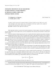
Argon gas blowing at a constant rate of 20 l min−1 at 45° onto the leading edge of the focused position Focused on the top surface of the material. 120 mm focusing lens from Lumonics Ltd (Borosilicate crown glass) 0.8 mm 1. Rectangular without a leading-edge power spike in the front of the pulse 2. Two step ramp-up pulse 3. Two step ramp-down pulse (see Fig. 2) 396 W, 330 W 0.6 ⇒ 8 mm s−1 4, 8, 12 ms 5.9, 7.5, 9.4, 11, 15 J for 4 ms 11.8, 15, 18.8, 22, 30 J for 8 ms 17.7, 22.5, 28.2, 33, 45 J for 12 ms (The APPDs are calculated to be 2.98 × 10⁹ W m−2, 3.73 × 10⁹ W m−2, 4.67 × 10⁹ W m−2, 5.47 × 10⁹ W m−2, and 7.46 × 10⁹ W m−2, respectively)
643
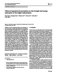
of confirming that the metal has sufficient ductility to bend round a specified radius and to see if any defects present initiate cracks [9]. The test strip prepared was 6 mm wide on each side of the weld fusion, and was 1.4 mm thick and 32 mm long. The welded specimen was placed across two rollers and pressed downwards by the rod-like former into the top surface (see Fig. 3). The lower root surface was in tension, until the sides were parallel. The surface was then examined for cracks and tears. The effects of operating parameters on the soundness and the compressive properties of the welded materials were fully investigated. The specimen size for the tensile tests on the laser welded sample is shown in Fig. 4 where the weld was at the centre of the specimen. An Instron 4204 test machine was used in this study. The tensile test was carried out at crosshead speed 2.0 mm min−1 and a sample rate of 1.0 pt s−1. The specimen prepared was gripped in the jaws of the testing machine and subjected to a tensile force which was slowly increased at suitable increments through the mechanical lever system until the specimen broke.
4. Experimental Results and Discussion 4.1 Effects of Operating Parameters on Hardness
Table 3 shows the microhardness results of the weld fusion zone for selected samples. The hardness of the parent material was measured as 100 ± 4 Hv and that of the fusion zone for selected samples was 120–141 Hv. The small difference in hardness of the fusion zone and the base material demonstrates their similarity in mechanical properties. In addition, the small increase in hardness maintains the characteristic of good formability of the zinc-coated sheet steel for automotive use. As for the effects of operating parameters, it can be seen in Table 3 that microhardness was enhanced with an increase in travel speed, owing to the faster cooling rate. However, it is worth noticing that the variations in the rest of the operating parameters, including the average peak power density, the pulse shape, the pulse duration, and the mean power, did not produce appreciable changes in the hardness. According to Eq. (10), the selected combination of operating parameters led to a high overlapping rate of spot welds. This can be further confirmed by the calculation that the percentage of weld overlapping required to produce visually acceptable seam welds was, in general, more than 90% for the different pulsed laser parameter set-ups. Hence, the difference in the cooling rate was slight when varying the pulsed laser parameters. On the other hand, the slight variation of hardness could be regarded as normal, and be associated more with the microstructural inhomogeniety. 4.2 General Discussion on Bend Strength of Welds
The ability of the welds to resist a bending load depends mainly on the size, the profile, the porosity distribution, and the microstructure of the fusion zone. All these factors are closely related to the heating effects of the defined processing conditions. The significance of the bend strength of welds lies
644
Y.-F. Tzeng and F.-C. Chen
Fig. 2. Examples of the real power pulses used in the study.
Fig. 4. A tensile test specimen.
Fig. 3. A diagram showing the method of testing longitudinal bend on specimens.
in the formability and the prevention of deformation of the workpieces, which are mutually opposing in practice. The higher the bend strength, the more difficult is the formability of the welded workpieces. Conversely, it is better at preventing deformation resulting from a mechanical shock such as an impact during a car crash. It was found in this study that there were no physical cracks or tears on the surface of the welds tested, which indicates
Effects of Operating Parameters
645
Table 3. The hardness results on selected visually sound samples pulsed with three different pulse shapes. Microhardness test Pulse shape APPD (W m−1 m−1) Pulse duration 4 ms Travel speed Mean power (W) (mm s−1) 1.8 396 2.0 396 2.3 396 2.6 396 1.8 330 2.0 330 Pulse duration 8 ms 2.2 396 2.3 396 2.6 396 2.9 396 1.8 330 2.0 330 Pulse duration 12 ms 2.2 396 2.3 396 2.5 396
5.47 × 10⁹
120 123 131 136 121 123
Rectangular 3.73 × 10⁹
121 124 127 133 124 122
that sound welds are produced in the identified operating region. The experimental results were presented in terms of the maximum load (kN) keeping the cross-sectional area the same for all specimens. The ratio of the maximum load applied for a defined displacement to the original cross-sectional area was measured as the compressive property of the welds and interpreted as the weld bend strength, which refers to its ability to withstand a specified bending load. The maximum load on the parent material was experimentally found to be 0.37 kN and for the selected welded specimen was 0.73–0.90 kN. The results show that the formability of the tested material was slightly reduced, but the prevention of deformation was enhanced after the welding process.
4.67 × 10⁹
Ramp-up 4.67 × 10⁹
Ramp-down 4.67 × 10⁹
124 125 121 130 123 131
126 128 120 133 126 127
121 122 125 135 123 127
121 124 136 141 125 128
123 123 131 140 124 131
125 123 128 138 125 130
125 124 129
128 126 134
122 126 129
4.4 Effects of Welding Speed on Weld Metal Strength
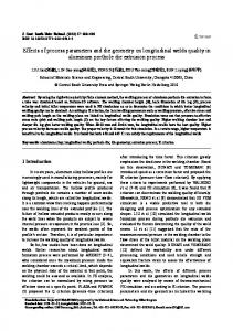
In theory, the bend strength of welds increases with decreasing travel speeds within the operating region, owing to an increase in the fusion zone. However, the existence of porosity is expected to result in a small variation in the trend of the bend strength distribution of welded samples over the travel speed. This can be observed clearly in Figs 5 to 7, in which for all power pulses, the experimental results were in agreement with the above principle. The sudden drop in bend strength with decreasing travel speed can most probably be attributed to the influence of porosity.
4.3 Effects of Pulse Shaping on Weld Metal Strength
Pulse shaping, accompanied by varying travel speeds under a given set of processing conditions, is known to be capable of altering the weld dimension and the quality of seam welds [10–12]. Therefore, the bend strength of welds can also be modified. The experimental results shown in Fig. 5 suggest that a ramp-down pulse generally produces a slightly larger bend strength than the other two pulses. This may be due to the ramp-down pulse shape producing the largest weld profile owing to its having the strongest heating effect. The ramp-up pulse produces the lowest weld profile. The difference in the bend strength among the three was marginal, and was approximately within the range of 0.1 kN. This was mainly because of the small difference in the weld profiles created by power pulse shaping.
Fig. 5. The dependency of the bend strength of the welds on welding speed and pulse shape.
646
Y.-F. Tzeng and F.-C. Chen
Fig. 6. The dependency of the bend strength of the welds on APPD and welding speed.
4.5 Effects of Average Peak Power Density on Weld Metal Strength
Figure 6 demonstrates that the bend strength of welds increased slightly with increasing average peak power density. This was due mainly to the fact that an increase in the size of the fusion zone at higher peak power density added to the bend strength of welds. 4.6 Effects of Pulse Duration on Weld Metal Strength
Figure 7 also shows that the bend strength increased slightly with increasing pulse duration, owing to an increasingly larger fusion zone because of the longer heating effect and increased energy of the power pulse. It was also noted that a slight
Fig. 7. The dependency of the bend strength of the welds on pulse duration and welding speed.
change in this theoretical prediction was observed in the case of a travel speed of 2.3 mm s−1 and pulse duration 12 ms (see Table 4). This is also most likely to be due to the existence of porosity. 4.7 Effects of Operating Parameters on Tensile Strength
Since the weld specimens do not have an obvious stressyielding point, all experimental results for the tensile test, presented in Table 4, were in terms of the tensile strength (MPa) and a percentage elongation (%). The tensile strength was essentially the fracture strength. All of the welded specimens have a measured tensile strength in the range 302.1– 284.6 MPa and a percentage elongation of 23.2%–31.6%. The
Table 4. Results of tensile tests on the welds using electrogalvanised coated steel sheet. Tensile test Pulse shape APPD (W m−1m−1) Mean power 396 W
Pulse duration 4 ms Travel speed (mm s−1) 2.3 2.0 1.7 Pulse duration 8 ms 2.6 2.3 2.0 1.7 Pulse duration 12 ms 2.3 2.0 1.7
5.47 × 10⁹
Rectangular
Ramp-up 4.67 × 10⁹
4.67 × 10⁹
Ramp-down 4.67 × 10⁹
F.S. (MPa)
Elong. (%)
F.S. (MPa)
Elong. (%)
F.S. (MPa)
Elong. (%)
F.S. (MPa)
Elong. (%)
291.3 294.2 293.1
27.2 28.5 26.3
290.5 299.2 295.7
27.0 24.2 28.2
294.9 290.5 297.2
29.5 26.9 26.6
284.7 291.0 296.3
23.2 29.9 27.3
294.9 293.1 293.8 290.7
25.8 28.7 24.2 29.4
294.6 292.8 290.0 295.9
28.7 27.3 24.4 29.6
296.7 290.0 290.6 292.0
25.8 25.3 24.5 29.6
290.5 298.7 295.7
29.8 27.2 25.7
284.6 300.4 295.0
26.0 28.7 25.9
297.6 296.1 292.9
26.3 24.0 27.9
Effects of Operating Parameters
results can be regarded as fairly consistent. The most important observation, however, is that all fractures occurred away from the weld zone. This confirmed that the joint strength of the selected visually sound welds was greater than that of the parent material. It was found that the location of most fractures was approximately 24 mm away from the weld junction. Since all the specimens broke at positions away from the weld, the tensile property observed was thus that of the parent material, and, hence, the values were reasonably uniform. It can be concluded that these parameters do not affect the tensile strength of the specimens.
5.
Concluding Remarks
A systematic evaluation of a series of selected acceptable welds by destructive testing has been described. The effects of the operating parameters of the Nd:YAG laser welding process on the mechanical static properties were noted. The results are summarised below. 1. Microhardness test. The welded samples showed an increase in hardness compared to the parent metal. The hardness was affected only by the traverse speed and was essentially independent of the pulsed laser parameters. 2. The bending test. No physical cracks or tears were present on the weld surface of the bent specimen. 3. The bend strength of the welded samples. This was increased with a decrease in travel speed and an increase in the pulsed laser parameters including pulse duration and APPD. 4. Effects of pulse shaping. It was found that a ramp-down power pulse produced the greatest bend strength, followed by a rectangular pulse with a ramp-up pulse producing the lowest-band strength. 5. Tensile test. Fracture was not initiated at the weld, but in the parent material. The operating parameters did not appreciably affect the tensile strength and the ductility of zinc-coated sheet steel after the application of the pulsed Nd:YAG laser welding process. Thus, no variations in weld properties were noted except that the weld was stronger than the parent material in all cases.
647
Acknowledgements
The authors would like to express their deep appreciation to Professor W. M. Steen, Dr Ken Walkins, and Dr Zhu Liu of the Laser Group at the University of Liverpool, UK for their substantial assistance in this work. The authors are grateful to the National Science Council of the Republic of China for supporting this research under grant NSC 89–2212-E-182–002.
References 1. M. Cantello, S. L. Bobbi, J. F. Flavenot and A. Diboine, “Laser welding thin sheets for car body structure”, ISATA’92, pp. 85– 91, 1992. 2. M. G. Forrest, W. A. Martilla and T. M. Burke, “A comparative analysis of laser and resistance spot welds”, IBEC’94, Automotive Body and Design Engineering, pp. 45–51, 1994. 3. S. C. Kennedy and I. M. Norris, Nd-YAG Laser Welding of Bare and Galvanised Steels, International Congress and Exposition, Detroit, MI, SAE Technical Paper Series 890887 February– March 1989. 4. I. Norris, T. Hoult, C. Peters and P. Wileman, “Material processing with a 3 kW Nd:YAG laser”, Proceedings of Laser Advanced Materials Processing (LAMP), Nagaoka, Japan, 1992. 5. A. Matsunawa, S. Katayama, H. Ikeda and K. Nishizawa, “Effects of pulse shaping on defect prevention in pulsed laser welding”, Proceedings of ICALEO(‘92), Orlando, Florida, USA, Laser Institute of America, pp. 547–556, 1992. 6. R. Aristotile, M. Fersini and V. Rusti, “Laser welding of steel sheets”, Second European Conference on Joining Technology, Florence, May 1994. 7. Y. F. Tzeng, “Parametric analysis of pulsed Nd:YAG laser seam welding process”, Journal of Materials Processing Technology, 102(1–3), pp. 40–47, May 2000. 8. British Standard Methods of Destructive Testing Fusion Welded Joints and Weld Metal in Steel, BS 709:1983. 9. R. A. Higgins, Materials for the Engineering Technician, 2nd edn, Edward Arnold, London, 1987. 10. H. N. Bransch, D. C. Weckman and H. W. Kerr, “Effects of pulse shaping on Nd:YAG spot welds in austenitic stainless steel, Welding Research Supplement, pp. 141s–151s, June 1994. 11. W. Pecharapa and A. Kar, “Effects of pulse changes on weld pool shape in laser welding,” J. Phys. D: Appl. Phys. 30, pp. 3322– 3329, 1997. 12. D. C. Weckman, H. W. Kerr and J. T. Liu, “The effects of process variables on Nd:YAG spot welds; Part 2. AA 1100 aluminum and comparison to AISI 409 stainless steel” Metallurgical and Materials Transaction, 28B, pp. 687–697, August 1997.