water Article
Efficiency of a Horizontal Sub-Surface Flow Constructed Wetland Treatment System in an Arid Area Abeer Albalawneh 1, *, Tsun-Kuo Chang 1,† , Chi-Su Chou 2,† and Sireen Naoum 3,† 1 2 3
* †
Department of Bioenvironmental Systems Engineering, National Taiwan University, Taipei 10617, Taiwan;
[email protected] Ecological Engineering Research Center, National Taiwan University, Taipei 10617, Taiwan;
[email protected] National Center for Agricultural Research and Extension, Al-Baqa’a 19381, Jordan;
[email protected] Correspondence:
[email protected] or
[email protected]; Tel.: +886-984250300 These authors contributed equally to this work.
Academic Editors: Alan Howard and Defu Xu Received: 30 November 2015; Accepted: 1 February 2016; Published: 5 February 2016
Abstract: The main objective of this study was to evaluate the performance and treatment efficiency of the Horizontal Sub-Surface Flow Constructed Wetland treatment system (HSF-CW) in an arid climate. Seventeen sub-surface, horizontal-flow HSF-CW units have been operated for approximately three years to improve the quality of partially-treated municipal wastewater. The studied design parameters included two sizes of volcanic tuff media (i.e., fine or coarse), two different bed dimensions (i.e., long and short), and three plantation types (i.e., reed, kenaf, or no vegetation as a control). The effluent Biological Oxygen Demand (BOD5 ), Chemical Oxygen Demand (COD), Total Suspended Solid (TSS), and phosphorus from all of the treatments were significantly lower as compared to the influent and demonstrated a removal efficiency of 55%, 51%, 67%, and 55%, respectively. There were significant increases in Electrical Conductivity (EC), sulfate, and calcium in the effluent of most HSF-CWs due to evaporative concentration and mineral dissolution from the media. The study suggests that unplanted beds with either fine or coarse media are the most suitable combinations among all of the studied designs based on their treatment efficiency and less water loss in arid conditions. Keywords: water reuse; constructed wetland; wastewater treatment; removal efficiency; Jordan
1. Introduction Constructed wetlands (CWs) have been recognized as a reliable wastewater treatment technology [1,2]. CWs are engineered systems that are designed and constructed to utilize natural processes that improve water quality in wetlands in a more controlled or modified environment [1]. Compared to conventional treatment systems, constructed wetlands can be more economical, easily operated and maintained, and therefore have a strong potential for applications in developing countries. Furthermore, CWs as a decentralized wastewater technology, can be applicable in rural and small communities, eco-cities, and individual households that do not have the resources or need for complex and costly centralized wastewater treatment systems [3,4]. There are two different types of constructed wetlands: free water surface (FWS) and sub-surface flow (SSF). SSF wetlands may be classified according to the direction of flow, either horizontal or vertical [5]. In developed temperate-climate countries, the horizontal sub-surface flow constructed wetlands (HSF-CWs) have been successfully used for the treatment of various types of wastewater for more than four decades [1,5]. However, to date there has been limited information about CWs in
Water 2016, 8, 51; doi:10.3390/w8020051
www.mdpi.com/journal/water
Water 2016, 8, 51
2 of 14
developing countries [3,6,7] particularly those located in arid and semi-arid areas. The adoption of CWs has been slow there due to the lack of understanding of CW’s potential benefits, Water 2016,surprisingly 8, 51 2 of 15 actual performance, and appropriate design features [7]. In addition, the selection and design of developing countries [3,6,7] particularly those located in arid and semi-arid areas. The adoption of CWs in arid areas requires proper consideration of the particular climatic conditions [8]. For example, CWs has been surprisingly slow there due to the lack of understanding of CW’s potential benefits, Vera et al. [8] performance, considered the time (HRT) and plant asand the design two important actual and hydraulic appropriateretention design features [7]. In addition, thespecies selection of design parameters hyperand super-arid areas. of the particular climatic conditions [8]. For CWs in arid in areas requires proper consideration Jordan is one five most water-deprived countries the world. The climate istwo generally example, Veraofetthe al. [8] considered the hydraulic retention timein (HRT) and plant species as the important design parameters in hyperand super-arid areas. arid to semi-arid; 90% of Jordan's land area receives less than 200 mm rainfall per year [9]. In Jordan, is one of the five most water-deprivedofcountries in theand world. The climate generally were Al-Omari etJordan al. [10] investigated the performance HSF-CWs, indicated thatisHSF-CWs arid to semi-arid; 90% of Jordan's land area receives less than 200 mm rainfall per year [9]. In Jordan, capable of reducing BOD, different forms of nitrogen, TSS, FC, and TC. Whereas, HSF-CWs design Al-Omari et al. [10] investigated the performance of HSF-CWs, and indicated that HSF-CWs were parameters such as mediaBOD, size,different HRT, bed dimensions, have not been studied or capable of reducing forms of nitrogen, and TSS, plantation FC, and TC.types Whereas, HSF-CWs design reported as yet. parameters such as media size, HRT, bed dimensions, and plantation types have not been studied Toorprovide needed information mentioned above, this study focuses on evaluating the reportedthe as yet. To provide needed information mentioned above, in thisarid studyclimates, focuses onwith evaluating the performance and thethe treatment efficiencies of HSF-CW an attempt to performance and the treatment efficiencies of HSF-CW in arid climates, with an attempt to comprehensively evaluate the various designs of HSF-CW on their removal of organic pollutants, comprehensively evaluate the various designs of HSF-CW on their removal of organic pollutants, heavy metals, anion, and cations, etc. Two types of media size (fine and coarse), two bed dimensions heavy metals, anion, and cations, etc. Two types of media size (fine and coarse), two bed dimensions (long and short) and three plantation types without vegetation as a control) (long and short) and three plantation types(reed, (reed, kenaf, kenaf, ororwithout vegetation as a control) were were tested to compare the proper combinations on their performance, and to subsequently identify the tested to compare the proper combinations on their performance, and to subsequently identify the major design criteria and and proper systems for inarid aridareas. areas. study conducted major design criteria proper systems forHSF-CWs HSF-CWs in TheThe study was was conducted from from November 2008 through November 2011. November 2008 through November 2011. 2. Materials and Methods 2. Materials and Methods Site Description 2.1. Site2.1. Description This study was implemented in the Al-Samra agricultural research station in central Jordan,
This study was implemented in the Al-Samra agricultural research station in central Jordan, 36 km 36 km northeast of downtown Amman and at an elevation of 550 m above sea level. The mean northeast of downtown Amman and elevation 550 m above The−1mean precipitation −1 and sea precipitation and evaporation of at theanregion is 123ofmm·year 1500level. mm·year , respectively ´1 and 1500 mm¨ year´1 , respectively (according to and evaporation of the region is 123 mm¨ year (according to Al-Samra meteorological station data from 2005–2014). Figure 1 shows the location of ourmeteorological study area. Al-Samra station data from 2005–2014). Figure 1 shows the location of our study area.
Figure Locationmap map of area. Figure 1. 1. Location ofthe thestudy study area.
A benchmark site for HSF-CW treatment systems was established in 2008. The system was
A designed benchmark site forand HSF-CW systems was established in 2008.in The system was to capture store thetreatment partially-treated municipal wastewater effluent an influent designed to capture and store the partially-treated municipal wastewater effluent in an influent holding pond, and then re-treat it through HSF-CW beds. The outlet water from HSF-CW beds was stored in another effluent-holding pond and then used for irrigating forest trees. The influent and
Water 2016, 8, 51
3 of 15
holding pond, and then re-treat it through HSF-CW beds. The outlet water from HSF-CW beds was stored in another effluent-holding pond and then used for irrigating forest trees. The influent and3 of 14 Water 2016, 8, 51 effluent holding ponds had capacities of 300 m3 and 150 m3, respectively. The HSF-CW system was comprised of 17 sub-surface HSF-CWs. The mean hydraulic residence time was two days. The 3 and partially treated municipal wastewater was m the only150 available source of irrigation in this research effluent holding ponds had capacities of 300 m3 , respectively. The HSF-CW system was station and therefore selected as the influent of our HSF-CWs. comprised of 17 sub-surface HSF-CWs. The mean hydraulic residence time was two days. The partially
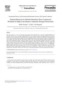
treated municipal wastewater was the only available source of irrigation in this research station and 2.2. Treatment System Design therefore selected as the influent of our HSF-CWs. The test site for the HSF-CW was divided into two main categories: (1) nine long beds with dimensions of 9.5 Design m × 1.7 m × 0.8 m (L × W × D). Coarse volcanic tuff (10–20 mm in diameter) was 2.2. Treatment System used as the wetland media. Three of the beds were planted with the reed plant Phragmites australis The test site forbeds the were HSF-CW was divided intoplant two Hibiscus main categories: long beds and three of the planted with the kenaf cannabinus. (1) Thenine remaining three with dimensions of 9.5 m ˆ 1.7 m ˆ 0.8 m (L ˆ W ˆ D). Coarse volcanic tuff (10–20 mm in diameter) beds were left without vegetation and were used as controls. (2) Eight short beds with dimensions was usedof as 6.5 themwetland beds withwith the reed Phragmites australis × 2.5 mmedia. × 0.8 mThree (L × of W the × D); fourwere bedsplanted were filled coarseplant volcanic tuff media (10–20ofmm diameter) and the other beds were with cannabinus. fine volcanicThe tuff remaining (4–8 mm inthree and three theinbeds were planted with four the kenaf plantfilled Hibiscus Two of the beds filledand withwere fine media and two of the filled with coarse were beds diameter). were left without vegetation used as controls. (2)beds Eight short beds withmedia dimensions of planted with reed plants; the remaining four beds did not have vegetation and were used as 6.5 m ˆ 2.5 m ˆ 0.8 m (L ˆ W ˆ D); four beds were filled with coarse volcanic tuff media (10–20 mm in controls. The area dimension and field facilities were the major variables that controlled the diameter) and the other four beds were filled with fine volcanic tuff (4–8 mm in diameter). Two of the distribution of the treatments discussed above. A schematic of the experimental layout is shown in beds filled with fine media and two of the beds filled with coarse media were planted with reed plants; Figure 2. In the middle of each bed, a tube was installed to facilitate daily measurements of the the remaining four beds did not have vegetation were to used controls. The area dimension 3 for each and water temperature. All long and short beds wereand designed haveasthe same volume (13 m field bed). facilities were the major variables that controlled the distribution of the treatments discussed 3 2 The total HSF-CW volume and surface area was 221 m and 275 m , respectively. The reeds above. A schematic the experimental is shown Figure In theinmiddle of each bed, were planted inofNovember 2008 andlayout removed at the in end of the2. study November 2011; thea tube was installed to facilitate measurements of the water temperature. Allsummer long and short planting density was daily nine rhizomes per square meter. Kenaf is an annual crop andbeds was were 3 for planted in three in 2009, 2010, 2011 from May until November, 20 transplants per area designed to have theseasons same volume (13 mand each bed). The total HSF-CWwith volume and surface 3 2 square meter. was 221 m and 275 m , respectively. The reeds were planted in November 2008 and removed at the this study, we use the2011; following abbreviations: long (L)nine bed, rhizomes short (S) bed, (C)meter. media,Kenaf end of theInstudy in November the planting density was percoarse square and fine (F) media. Reeds, kenaf, and no vegetation will be referred to as R, K, and N, respectively. is an annual summer crop and was planted in three seasons in 2009, 2010, and 2011 from May until For example, the long bed with coarse media planted with reeds will be referred to as (LCR) and November, with 20 transplants per square meter. likewise for all of the treatments discussed above.
Figure 2. The horizontal sub-surface flow constructed wetland treatment (HSF-CW) system layout.
In this study, we use the following abbreviations: long (L) bed, short (S) bed, coarse (C) media, and fine (F) media. Reeds, kenaf, and no vegetation will be referred to as R, K, and N, respectively. For example, the long bed with coarse media planted with reeds will be referred to as (LCR) and likewise for all of the treatments discussed above.
Water 2016, 8, 51
4 of 14
2.3. Wastewater Quality Monitoring The HSF-CW beds’ influent and effluent water were sampled and analyzed by the Jordanian National Center for Agricultural Research and Extension on a bimonthly basis which lasted for 18 months from November 2008 until August 2011. In all, 327 water samples were collected and analyzed for 21 water quality parameters. The chemical and biological characteristics of wastewater used in this study were: Biological Oxygen Demand (BOD5 ), Chemical Oxygen Demand (COD), pH, Electrical Conductivity (EC), Total Suspended Solid (TSS), FC, sulfate (SO42´ ), magnesium (Mg2+ ), calcium (Ca2+ ), chloride (Cl´ ), sodium (Na+ ), potassium (K+ ), zinc (Zn), cadmium (Cd), cobalt (Co), chromium (Cr), lead (Pb), arsenic (As), phosphorus (P), carbonates (CO3´ ), and bicarbonates (HCO3´ ). The samples were analyzed according to the Standard Methods for the Examination of Water and Wastewater [11]. Details about the sampling procedure, preparations, and instruments are available in the manual [12]. For each water quality parameter, the removal efficiency (%) was calculated based on mass flow difference between the effluent and influent relative to the influent. 2.4. Wastewater Flow Rates and Distribution Two water meters were used to measure the influent flow rates, each of them located in the main influent supply line as shown in Figure 2. Influent flow rate was controlled to be the same for all the beds through an identical flow rate controller with 17 feed lines, each one installed at the entry point of each bed. Calibration of water flow for even distribution was done before starting up the system. The mean of the two influent water meter readings divided by 17 was used to determine the influent flow rate for each bed. Due to water shortage, our total wastewater share varied from 35 m3 ¨ day´1 in the winter seasons to 25 m3 ¨ day´1 in the summer seasons, as regulated by the governmental water conservation policy. An additional water meter and controller for 17 outlet lines were used for effluent flow rate measurement; each one was installed at the end of the bed. However, since the effluent flow rate from each bed was very low the water meters did not work properly. Therefore, we manually measured the effluent flows, and collected two-hour composite effluent samples for each bed. We repeated this measurement six times for each bed, three times in the winter seasons and the other three in the summer seasons. 2.5. Statistical Analyses We used the Statistical Package for the Social Sciences (SPSS 16) software to conduct statistical analyses. Coinciding with our experimental design and goals, the Kruskal-Wallis test was used to conduct our comparisons. The first comparison was performed between the influent and effluent of each bed. The effluents of LCN, LCK, and LCR were compared as a group 1. Likewise, SCN was compared to SCR as a group 2, SFN to SFR as a group 3, and SC to SF as a group 4. SC and SF media were calculated as SC equals the mean of (SCN and SCR) and SF equals the mean of (SFN and SFR). Moreover, the effluents of LCR were compared to SCR, and the effluents of LCN were compared to SCN to figure out the differences between long and short beds efficiency. Significance was recognized when α