finement technique in combination with a shadow coherence method. Key words: Rendering- Radiosity - Ray tracing - Source selection - Shadow co- herence.
i i i i ~ % -~
~
.
Efficient, complete radiosity ray tracing using a shadow-coherence method Arian J.F. Kok 1, Frederik W. Jansen 1, and Charles Woodward 2 Delft University of Technology, Faculty of Technical Mathematics and Informatics, Julianalaan 132, NL-2628 BL Delft, The Netherlands e-mail: arjan[fwj @duticg.twi.tudelft.nl 2 Helsinki University of Technology, Institute of Industrial Automation, Otakaari 1, SF-02150 Espoo 15, Finland
Most two-pass rendering methods calculate a radiosity shading for each patch or element in a scene in the first pass. This shading contains two components: one for the light received directly from the main light sources and one representing the intensity of the light received indirectly by means of diffuse and specular interreflection between patches. However, it is very difficult to achieve accurate representation of the distribution of this radiosity shading over the patch, particularly where clearly visible shadow boundaries exist. A better approach is to store only the indirect reflection component in the form of radiosity shading, and to calculate the direct reflection component during the second pass by casting shadow rays. This approach normally requires that many shadow rays must be cast. However, the number of rays for shadow testing can be kept low by selecting only those light sources that substantially contribute to the shading of a patch and applying an adaptive image refinement technique in combination with a shadow coherence method. Key words: Rendering- Radiosity - Ray tracing - Source selection - Shadow coherence Correspondence to: F.W. Jansen The VisualComputer(1993)10:19-33 9 Springer-Verlag1993
1 Introduction In recent years, several attempts have been made to integrate radiosity and ray tracing. Approaches proposed either extend the conventional ray tracing algorithm to include diffuse interreflection or extend the conventional radiosity method to add a specular component to the reflection. Proponents of the first approach, the extended ray tracing algorithm, are Kajiya (1986) and Ward et al. (1988). The second approach, the two-pass rendering method, has been pursued by many people (Wallace et al. 1987; Sillion and Puech 1989; Heckbert 1990). While using ray tracing for the specular reflection, they continued to use the traditional radiosity approach (Goral et al. 1984; Cohen and Greenberg 1985) in the sense that they include in the radiosity shading (calculated in the radiosity pass and stored with the patches) light received both directly and indirectly from the light sources. Ray tracing only serves to add the specular component, which could not be added to the radiosity shading without great difficulties (Immel et al. 1986). The main problem of this approach is that total radiosity often shows much variation over a patch. This is mainly due to the component of light received directly from strong (point) light sources. This component is responsible for clearly visible shadow boundaries. It is nearly impossible to represent these intensity variations accurately. Methods that have been proposed, such as adaptive patch refinement (Cohen et al. 1986), shadow meshes (Campbell and Fussell 1990), and illumination maps (Arvo 1986; Heckbert 1990), require large data structures and fail to provide the dynamic adaptation needed, for instance, for zooming in on a single patch in a very large scene. Heckbert's (1990) suggestion of making the radiosity calculation viewpoint dependent by restricting it to those patches that are prominent in a given view reduces the problem, but does not solve it. Also, the viewpoint-dependent expansion of the patch database does not make the method very suitable for hardware implementation. A better approach, therefore, seems to be to extend the ray tracing algorithm by taking into account not only the incoming light from the main light sources (by casting shadow rays) but also the light reflected by the other patches in the environment (diffuse and specular interreflection). This indirect reflection can be sampled by casting additional shadow rays in all directions which, unfortunately, leads to an explosion of rays. Solutions proposed by Kajiya (1986) - path tracing and importance sampling - and Ward et al. (1988) - illuminance caching 19
- reduce the number of shadow rays, but still require a large number of rays per pixel or the use of large data structures. Shirley (1990) has found a nice combination for the different ray tracing and radiosity approaches. He calculates the indirectly received light for each patch in a radiosity step and stores it as the radiosity shading with the patch. Because this shading is assumed to be almost constant over the patch, it does not cause the same resolution problems as in complete radiosity shading. Directly received light (from the main light sources and most radiant patches) is then calculated during the rendering pass by casting shadow rays, as in the traditional ray tracing algorithm. Basically, his method uses the conventional ray tracing algorithm, except that instead of an ambient term a more accurate calculation is made for indirect interreflection. Although the number of shadow rays is strongly reduced compared with the extended ray tracing algorithms (because only the most important light sources and patches are sampled), the number of shadow rays is still large. To reduce this number, Shirley relies on the same techniques as Kajiya: path tracing and importance sampling. As an alternative, we propose two other methods to reduce the number of shadow rays. First of all, for calculating the direct light, we use only those light sources that strongly contribute to shading gradients (shadow boundaries) on the patches. We call this source selection (Kok and Jansen 1991). If a light source is weak, we add its contribution to the indirect shading. Secondly, we propose to exploit shadow coherence. By applying an adaptive image refinement method in combination with a so-called shadow image buffer, as proposed by Woodward (1990), the number of shadow rays can be considerably reduced. The results are high-quality pictures with accurate shadows at moderate costs. In the next section, we discuss in more detail the high-quality rendering algorithms and describe the separation of direct and indirect illumination. In Sect. 3, we review the criteria relevant for source selection. In Sects. 4 and 5, we discuss shadow ray efficiency methods and propose a method for reduction of the number of shadow rays by exploiting shadow coherence. In Sect. 6, we describe the complete algorithm and its implementation, and in Sect. 7 the results of our experiments. Results are summarized in Sect. 8.
20
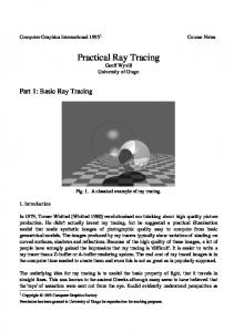
2 High-quality rendering by ray tracing and radiosity methods High-quality rendering strives to model accurately all aspects of light reflection in complex environments. An exact computation would involve the solution of complex integrals taking into account complex reflectance and transmittance functions (Kajiya 1986; Hall 1988; Bouville et al. 1988). To make the calculation feasible for complex scenes, the reflection model must be simplified by suitable approximations for the different aspects of light reflection. A first approximation is to assume that light reflection is either diffuse or specular. Diffuse (Lambertian) reflection distributes light evenly in all directions, whereas specular (mirror-like) reflection reflects the light in only one direction. Diffuse reflection is therefore viewpoint independent, whereas specular reflection is viewpoint dependent and only appears at points where the view directions coincides with the direction of the reflected light. As light travels through an evironment, it may be reflected diffusely, specularly, or in a combination of both, depending on the properties of the surfaces it meets. Fig. 1 a shows some paths a light ray may travel before it meets the eye (viewpoint). To simplify the explanation, all surfaces are assumed to be either purely diffuse or purely specular. Standard, recursive ray tracing (Whitted 1980) takes into account both direct diffuse (path l - c - v in Fig. 1 b) and direct specular reflections ( l - g - v ) as well as indirect specular reflections ( l - a - h - v). Compared with projective display algorithms (e.g., the depth-buffer algorithm), ray tracing can simulate mirroring reflections, because it can trace a light ray backwards until it meets a diffuse surface ( l - a - h - v ) . However, it does not take into account the important contribution of the light that is specularly reflected by mirroring surfaces in the environment onto diffuse surfaces ( l - d - f - v ) . To capture this light, Arvo (1986) proposed a preprocessing pass (backward ray tracing), in which rays are shot from the light sources and the mirrored reflection is stored in illumination maps on the surfaces of the objects. The second pass then "meets" the first pass at the patches (at f in Fig. 1 c). The other type of reflection, not accounted for in traditional ray tracing (usually approximated coarsely with an ambient term), is the diffuse interreflection between patches ( l - e - b - v in Fig. 1 d). Each
{'3omputcr su'al-lightsource
t
b
~
"N~ ' "diffuse
] 0 lightsource diffusea ~ ~ " ~ e b ~ ~'/\diffuse
l Qlight source a,~J~__------~ ". e b ~ : diffuse diffuse~f ~ ~fg
c
d
specular
v ,Q,
a
diffuseb
~
d
~
b
~,
v C
screen
~
diffuse
r "
~gh
W d
screen
screen
~.
cL4/
ecular
~,
screen
Fig. l a-d. Light reflection and different types of ray tracing: a direct and indirect reflection; b recursive ray tracing; e ray tracing with backward ray tracing; d ray tracing with diffuse interreflection
patch not only receives light from light sources, but also light that is diffusely reflected from other patches. This diffuse interreflection can also be calculated by ray tracing, but then, for each ray intersection, additional shadow rays must be cast into the environment to sample the light incoming from all directions. If the light reflected by the other patches is not known (i.e., if no radiosity preprocessing is applied), then the sampling must be performed recursively until further contributions become insignificant. This is very expensive. Kajiya (1986) therefore proposed reducing the number of rays by following only one randomly selected ray for each level of recursion. Additionally, only one randomly selected light source is taken into account for shading each intersection point. Kajiya calls this path tracing. The effectiveness of the sampling can be increased by importance sampling (Kajiya 1986), which distributes rays over the different directions and light sources in such a way that the number of rays in each direction is proportional to the "impor-
tance" of the related light sources and patches. To each light source and patch is assigned a probability factor proportional to the intensity contribution of that light source or patch. This probability factor must ensure that shadow rays are sent at least to the nearest and brightest light sources. The importance of a light source or patch with respect to another patch can be estimated dynamically during the sampling process or in advance, on the basis of its intensity (if known) or size and form factor (occlusion factor). This a priori estimation strives more or less to obtain the same information as is explicitly calculated with a radiosity method. A serious drawback of these stoachastic approaches is that although they reduce the number of secondary and higher generation rays, they still require a large number of primary (viewing) rays for each pixel. Thus, they work well for images that are heavily supersampled (many rays per pixel), but generate a great deal of noise when the sampling density is low. Ward et al. (1988) have proposed a technique (illu-
21
minance caching) that exploits shading coherence
Recursive generation of secondary rays can also be avoided by applying a radiosity-preprocessing approach to obtain a coarse indication of the shading for each patch. These preprocessed values can then be read by the secondary rays. The result is a "one level" path-tracing algorithm (Rushmeier 1988). In the same manner, Shirley (1990) proposed an algorithm based on a separate computation of directly and indirectly received light. The latter is calculated by a radiosity method. First, the indirectly specularly reflected light is captured in illumination maps. Second, a global illumination calculation is performed for the whole scene. Then, for each patch, the light received directly from light sources is subtraced from the patch radiosity value by following the light again from the sources and subtracting the influences of the light rays from the patch radiosity values. The resulting radiosity shading shows only minor intensity variations. The patch refinement can therefore be relatively coarse. Finally, during the rendering pass, light received directly from light sources is calculated by casting
and is based on the assumption that sampling density can be adapted to the shading gradients. Areas with low gradients can be sampled sparsely, while areas with large gradients should be sampled more densely. This is implemented by storing calculated surface intensities and interpolating these values for subsequent rays. Initially, all rays are recursively traced to full depth, but after some time the number of secondary rays diminishes. Object coherence criteria are used to determine whether earlier calculations provide enough information. Extra samples are required for areas with high surface curvature and near edges of objects, while interpolation is possible for points on flat patches, not too close to other patches. An advantage of Ward's method is that only those areas involved in the light reflection for a particular view are sampled. A drawback of the method is the quantity of data to be stored and the overhead for retrieving the information can be quite large. Ward et al. suggest using an octree type of data structure in addition to the object model.
IC)light source
"N~'~df,ffuse
diffuse " J ~ d
h ecular
sp
a
~,,
screen
,g, I
~liffuse
~
h ;pecular
\ ~ specular
b
v
d i f f u s e ~
C
~
diffuse
~f
d specular
specular
screen
screen
,Q,
light source ffuse
specular
~ecular
screen
22
diffuse
~,
dif
d
I light source
I lightsource
v
Fig. 2a-d. Two-pass radiosity method on the basis of ray tracing (a, b) (Wallace et al. 1987) and ray tracing with radiosity preprocessing (c, d) (Shirley 1990): a first pass; b second pass; e first and second passes; d third pass
t. shadow rays to the light sources as in standard ray tracing, whereas the indirect component is calculated by taking the sum of the radiosity value and the illumination m a p value, as in conventional radiosity shading and backward ray tracing. Figure 2 shows the steps of Shirley's algorithm (Shirley 1990) compared with the traditional two-pass methods (Wallace et al. 1987). Of course, there is only a gradual difference between Rushmeier's and Shirley's methods. Radiosity preprocessing, used in Rushmeier's algorithm exclusively to obtain a global indication of the radiosity of each patch in order to answer ray queries, is used in Shirley's algorithm also to approximate the radiosity shading of the patch, which eliminates the need for sampling the diffuse interreflection between patches again. Furthermore, the distinction between directly and indirectly received light from light sources is rather arbitrary, because indirectly received light from a very strong light source may be stronger than the directly received light from a very weak light source. Imagine, for instance, a strong spotlight directed on a white wall. Although most of the other patches will not receive direct light from this spotlight, the light received indirectly may still create sharp shadows on these patches. Therefore, the classification of whether a light source or patch should be sampled by shadow rays or whether its contribution can be covered by the preprocessed radiosity should not only be based on whether the light is received directly or indirectly, but also on the "importance" of its contribution to creating shading gradients (shadows) at individual patches. Light sources and patches should, therefore, be classified, and the strongest light sources and most radiant patches should be selected for the "direct" lighting computation (Kok and Jansen 1991). Other light sources and less radiant patches are treated by indirect light computation. In Chen et al. (1991), a similar source classification is used to separate the calculation of the high-frequency intensities (clearly visible shadow boundaries) from the low-frequency intensities (minor intensity transitions). This separation in two passes is part of the authors' adaptive refinement strategy: initially, an approximated image is calculated at low cost for previewing reasons. Later, this image is gradually refined so that a more accurate picture is obtained. This strategy can also be interpreted in the sense that initially the value of the diffuse interreflection is based on the radiosity step (Shir-
:)mputer
ley's algorithm) and, in subsequent passes, a more accurate calculation of the diffuse reflection is calculated by sampling the whole environment with shadow rays (Rushmeier's algorithm). Source classification is thus an important tool to trade-off accuracy for speed. From a theoretical point of view, source classification provides an interesting generalization for the different radiosity algorithms: - If none of the light sources is selected for shadow ray casting, either for a high-frequency or for a low-frequency pass, then we have the conventional two-pass radiosity method (Wallace et al. 1987; Sillion and Puech 1989). - If all light sources and patches are selected for shadow ray casting, then the algorithm converts to the most extended form of ray tracing (Kajiya 1986) or the Rushmeier's algorithm in case of a radiosity preprocessing (Rushmeier 1988). If a limited number of light sources or radiant patches are selected for direct lighting (high-frequency pass), then the algorithm converts to Shirley's algorithm (Shirley 1990; Kok and Jansen 1991) or Chen et al.'s algorithms (1991), depending on whether the indirect light (low-frequency pass) is sampled or not. -
3 Source classification and selection Source classification strives to estimate the contribution of individual light sources and other radiant patches to the shading gradients (shadow contrasts) of individual patches in order to make a selection of the most important light sources (and most radiant patches). A source selection can be made globally, in which case a priority order of light sources is established for all patches in a scene, or locally, in which case a separate priority order is established for each individual patch or cluster of patches. An obvious choice for the global light source selection is to take the n most emitting or most radiant patches, i.e., the first n patches that are selected in the progressive refinement (shooting) radiosity method. However, this global selection neglects the fact that a light source can have a strong effect on some patches, but may have a negligible influence on other patches. Therefore, it is better to make a local selection, i.e., select for each patch the n most important light sources. Local selections show large differences due to dif-
23
dAj
01
Fig. 3.
F o r m factor from differential area i to differential area j
ferent locations with respect to strong light sources. Because of this, care should be taken that patch boundaries do not become visible due to different light source selections. It may, therefore, be advisable to make only source selections for clusters of patches (i.e., objects). To estimate the importance of a light source for a patch, we have to analyze the different factors that determine the contribution of the light source to the radiosity of the patch. The amount of diffusely reflected intensity by a point (delta area dAz) on patch i received from a patch j is given by
Irefl.=lpilj ~ cosOi6jido) =pilj ~ 6ji cos 0i cos 0j dAj, 7~r 2 g? where Irefl. = reflected intensity, Ij = intensity at patch j, p~ = reflectance/transmittance coefficient of patch i, = solid angle with respect to patch j, 0~, 0j = angles between the surface normals and the incoming and outgoing directions at dA~ and dAj (see Fig. 3), 6j~ = a visibility term, 6i~= 1 if dA i can see dA~ (if there is no object between the patches), else it is 0, and do
,
c o s O~
=delta solid angle, am ~--r~-~ dAj.
The amount of energy leaving patch j that is reflected by a point on patch i is thus dependent on the radiosity of patch j and on the form factor defining the fraction of the energy leaving patch j that arrives at a point on patch i. This form factor is determined by several geometric factors, such as the mutual distance and orientation of the patches, as well as a visibility term. Finally, note
24
the total amount of reflected energy is also dependent on the reflectance coefficient, which is a physical property of the surface of patch i. Based on these observations, we can give the following criteria to select a patch j to be a light source for patch i. If the energy received by patch i coming from patch j is larger than a certain threshold value, then patch j is considered as a possible light source. We call this the radiance criterion. As mentioned, the reflected energy and thus the shadow contrast is not only dependent on the received energy, but is also dependent on the amount of light diffusely reflected by the patch. It is therefore not necessary to cast shadow rays for a patch whose diffuse reflectance is almost zero (i.e., a perfect specular reflective patch), eventhough it receives much energy from patch j. We call this the
reflectivity criterion. Although the total received and reflected energy is important for finding possible shadows on a patch, the distribution of light over a patch is also important. If the light coming from patch j gives large intensity variations over patch i, then patch j should be considered as a light source for patch i. On the other hand, if it can be detected a priori that light from a strong light source shines on the whole patch i or does not reach patch i at all, then the contribution of patch j, if any, can be added to the pre-calculated radiosity shading. The shading gradient over the patch depends on the visibility factor. If, for all points on patch i and all points of patch j, the visibility term is 0 or 1, then the shading is smooth, otherwise shadow boundaries appear. We call this the gradient criterion. If the integral specified above is approximated by ray tracing, then the accuracy of the result depends on the resolution of the rays, i.e., the number of rays per solid angle. If a possible light source (patch j) is small (e.g., is a point light source) or is seen with a small solid angle from patch i, then only one or a few shadow rays are needed. Shadow rays are then effective, and patch j is likely to be chosen as a light source. If, however, the possible light source is an area light source and the solid angle is large, then many rays are needed and patch j is not likely to be chosen as a light source. Also, the soft shadow that may be expected from an area light source can very well be represented by radiosity shading. Thus, based on the solid angle, it is determined whether shadow rays will be cast or
not, and if so, how many shadow rays will be needed. We call this the solid angle criterion. Finally, it may be observed that patches farther away from the viewer are not so critical for the perceived image quality. An approximated shadow computation can be accepted and the number of shadow rays can be reduced or limited to only the most important light sources (contributions of the other light sources are added to the general radiosity). We call this the distance criterion. For animation, this criterion should not be used so as to avoid having different selections between two frames, resulting in sudden changes of shadows. If all criteria indicate that a source should be selected for a patch, then the source is selected and shadow rays are cast to the source when the patch is hit. Of course, the number of light sources is always a compromise between the desired quality on the one hand and the processing time for the additional shadow rays on the other. An effective stepwise refinement strategy can be implemented by making a smooth transition between the high-frequency pass and the low-frequency pass as used by Chen et al. (1991). Initially, the general radiosity term is displayed and starting with the most important light sources, their contribution is calculated more accurately with shadow ray tracing by subtracting their estimated contribution from the general radiosity value. During the last step, light sources and patches that failed to enter the list of prominent light sources are sampled to compute the diffuse interreflection more accurately. A viewpoint-dependent version, comparable with the strategy proposed by Heckbert (1990), can be realized by making the source selection dependent on the viewpoint (applying the distance criterion).
4 Efficiency of shadow ray tracing Even though the number of shadow rays is now greatly reduced compared with the extended ray tracing algorithms (because now only rays are cast to a selected number of light sources and highly radiant patches), the number of shadow rays is still considerable. This is certainly true if large area light sources are taken into consideration. Given the cost of the large number of shadow rays, how can we improve on this ? First of all, we can use conventional ray tracing efficiency techniques, such as bounding box and
spatial subdivision techniques. Furthermore, the program can be implemented on a multiprocessor system or on a system with dedicated VLSI hardware. In Shen et al. (1992), a method is proposed that combines spatial subdivision techniques with the use of dedicated hardware. In this method, each ray frustum is subdivided into a number of sectors that all contain a number of rays capable of being processed in parallel on a dedicated pipe-lined architecture for ray-patch intersection. The sector data structure intersects a regular space subdivision, and patches that intersect a sector are retrieved for ray intersection. The width of each sector is estimated by the expected distribution of the patches. This estimation can be performed statistically (determined dynamically) or deterministically (by preprocessing). Although ray-efficiency techniques and special hardware implementations speed up the ray tracing process, a reduction of the number of rays is also needed. One way of achieving this would be to follow Kajiya (1986) and Shirley (1990) and resort to "path tracing" and "importance sampling." However, in that case a large number of rays is still needed to achieve an accurate result. Alternatively, one could follow Ward et al. (1988) and try to exploit object coherence by storing intermediate results. This would require the use of an additional data structure, although smaller than for their original method, because now only the results of primary rays are stored. Instead, we propose a method that simultaneously provides a significant reduction of shadow rays while using a compact data structure. The method is based on evaluating shadows by coherence properties during a recursive image-refinement process, as is described in the following two sections.
5 Shadow coherence Coherence methods can be divided into image space and object space methods. Image space coherence methods take advantage of the fact that intensity gradients are not evenly distributed over the image plane. By starting with a coarse sampling pattern and by applying an adaptive refinement to this pattern guided by local intensity gradients, the total number of rays for areas where the intensity is fairly constant, is greatly reduced (Whitted 1980; Roth 1982; Jansen and van Wijk 1984). Im-
25
age coherence works well for relatively simple pictures. However, as the complexity of the image increases, savings are negated by the overhead. The most important reason for this is that image coherence methods compare intensities of neighboring samples (i.e., pixels or rays), but do not provide information about what really caused the intensity variations. Variations in image intensity may be due to several factors, such as object colors, shadows, highlights and textures. Recalculating all these factors for a new sample point is expensive and in most cases redundant. Therefore, it pays to store relevant information, check for subsequent sample points what causes intensity differences, and refine only for that particular factor. Object space coherence methods try to do this by exploiting information about the image function, i.e., modeling and shading parameters. Some of this information can be directly deduced from the model input data and some can be derived from earlier samples and be stored for subsequent use, as by Ward et al. (1988). Akimoto et al. (1989) have carried this approach to an extreme. They store for
a
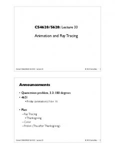
each primary ray a complete shade tree with all the secondary rays and all information about the intersected objects, i.e., their attributes, such as textures, transparencies, and curvatures. Similarity of rays can be examined precisely by comparing the tree structures and if, for instance, shadow appearances are the same, any further shadow calculation is not necessary. Of course, the quantity of data to be stored is enormous. Recently, Woodward (1990) presented a more compact data structure, shadow image buffer, to store relevant information for the shadow calculation. Unlike earlier methods - e.g., the light buffer (Haines and Greenberg 1986), which uses ray coherence in object space, or voxel-occlusion testing (Woo and Amanatides 1990), which is based on uniform voxel-traversal-grid structure - the shadow-image-buffer method exploits shadow coherence directly in image space. While shadow patterns caused by several light sources may be quite complex, the shadow shapes caused by each light source separately tend to be very homogeneous (Fig. 4). This property of shadow coherence can
b
Fig. 4a--d. Shadow coherence: a sphere with three light sources; b shadow image for light source 1; e shadow image for light source 2; d shadow image for light source 3
26
t, omputcr be exploited to reduce the number of shadow rays when refining the image. According to the method presented by Woodward (1990), a bitplane (SIB) is added to the frame buffer for each light source. Each SIB entry corresponds to a sample or pixel in the actual image and keeps track of whether the point is in shadow or not with respect to that light source. First, the image is sampled at a low resolution, say one sample for four pixels. All shadow rays are computed as usual and the shadow results are stored in the SIB. When the image is then refined, the shadow evaluation of any new sample, i.e., primary-ray-intersection point, is performed as follows: (i, j) = new sample; for (each light point L)
begin if (all already computed items neighboring SIB (L, i,j) are equal) shadow_result=value of neighboring SIB items; else shadow_result = cast_shadow_ray (intersection point, L); if (not in antialiasing) SIB (L, i, j)=shadow_ result; end. Shadow rays are thus cast only at shadow boundaries, where the neighboring SIB values differ. The obtained shadow values are stored in the SIB for the next pass. See the example of Fig. 5, which shows how the shadows of a sphere are refined. The SIB method imposes practically no time over-
Fig. 5a-d. Shadow refinement: a low-resolution image of sphere; b shadow image for one light source; e refined image of sphere; d refined shadow image of one light sourco
27
.3tsmJ head to the basic ray tracing algorithm and it is also simple to implement. Unlike other shadowacceleration methods that typically rely on polygonal approximations, the SIB method is also accurate with curved objects inasmuch as the shadow boundaries are ray traced. Because of its compactness, the SIB method is particularly useful for scenes with multiple light sources. When using the shadow buffer also for area light sources, they can be subdivided into a number of point-light sources. Each point light source then has one SIB entry. Because the shadow-image buffer is used, in determining the fraction of light that reaches a point from a point light source only rays are cast to the parts of the source where the shadow transition occurs.
6 Algorithm and implementation Combining Shirley's method (1990) with source selection and the adaptive image refinement technique based on shadow coherence, the outline of the new two-pass algorithm is as follows. In the first pass the global radiosity in a scene is determined with a progressive radiosity (" shooting") algorithm (Cohen et al. 1988). However, during the shooting a distinction must be made between light received directly (and through specular reflection) from the light sources and light received by diffuse interreflection. The sum of both should be used to calculate the global illumination, but only the indirect component is stored as the radiosity shading of a patch. We therefore propose the following modified "shooting" algorithm. Select a number n for the number of light source contributions that have to be stored separately in a list at each patch-mesh element (or at each mesh vertex) along with a general radiosity value that represents the contributions of all other patches and light sources. Start with the strongest light source and shoot its light, then continue with the next strongest and so on. Maintain the n most important contributions in the list. If a light source or patch is not entered into the list or is replaced by a stronger light source, then add its contribution to the general radiosity value. Before rendering, a further (local) selection can be made by reducing the n light sources to rn (m < n, m is variable) light sources based on reflectivity, gradient, and solid-angle criteria. If, for a patch
28
and possible light source, all these criteria are satisfied, then the source is chosen to be important for the patch. Thus, if this patch is hit during ray tracing, shadow rays are cast to the source to calculate the source influence. If the source is not selected, then its preprocessed contributions are added to the general radiosity values of the patch. After source selection, these general radiosity values of a patch represent a " m i n o r " or "low-frequency" illumination, which does not contain important shading gradients. Radiance and reflectivity criteria are implemented by calculating the unoccluded contribution of a possible source to the intensity of one (or more) point(s) on a patch. If this value is larger than some given threshold, then the source is chosen. The gradient criterion is implemented by comparing the preprocessed contributions of a source at the vertex points of a patch. If these contributions show large differences, then some kind of shadow or shading boundary appears on the patch and the light source should be sampled with shadow rays during rendering. If the patch is evenly lit, then the contribution can be added to the general radiosity value. Of course, as with all coherence methods, care should be taken not to miss small shadow details. With the solid angle criterion, the number of shadow rays that have to be cast from the patch to the light source is determined. First, the solid angle for which a possible source is seen is calculated. If this solid angle is larger than some threshold, then the source is not chosen. If the solid angle is smaller, then the fraction of the complete hemisphere it occupies is calculated. This fraction multiplied with the number of rays we would use for sampling a complete hemisphere (a user defined variable) yields the number of shadow rays we need to sample the source from the patch. A limited version of the distance criterion, the view criterion, is implemented. With the viewing parameters, the projection of a patch on the screen can be determined. If the number of pixels that the patch will occupy is known, we can determine how good the meshing for the patch is. If each mesh element is projected on only one or a few pixels, then interpolation of the preprocessed contributions gives a good representation of possible shading gradients and no source is chosen. When the mesh elements are too large, then shadow rays are cast, the number of rays being dependent on the other criteria.
3"'isua|
,
.ompmcr
As mentioned earlier, it is advisable to apply the same selection of light sources to neighboring patches (for example all patches in one object or patches attached to each other) to avoid patch boundaries becoming visible. In the second pass, the scene is rendered with an adaptive stochastic ray tracing algorithm (Dipp6 and Wold 1985; Cook 1986; Painter and Sloan 1989). First, the image is sampled at low resolution with shadow rays cast to all light sources (no shadow rays are cast for patches that backface the light source). The intensity at a point on a patch is the sum of the contribution of the (interpolated) radiosity of the patch for that point and the contributions of the selected light sources. The result (whether a light source is visible or not) is stored for each sample in the SIB. Instead of storing the SIB as a bitplane at the frame-buffer, we store it in the image-sampling datastructure, which contains all screen sampling information. This enables us to use the shadow image buffer also during antialiasing. To sample area light sources, they are subdivided into a number of smaller sources. This number is equal to the number determined with the solid angle criterion. To each small area, a ray is cast to a jittered point on this area. In subsequent steps the image is refined, but now shadow rays are only cast for "shadow boundaries." Several image refinement criteria are successively applied to sample the screen adaptively: - O b j e c t c r i t e r i o n . If neighboring samples do not all hit the same object, extra samples are taken to discover the exact object boundaries. - S h a d o w c r i t e r i o n . If neighboring samples do not show the same shadow property (all light or all shadow, which can be seen from the SIB), then a shadow boundary exists and extra samples are taken in this region to find the exact shadow boundaries. This criterion is only applied to real point light sources, because only these sources give sharp shadow boundaries that need to be antialiased. - D i f f e r e n c e ( g r a d i e n t ) c r i t e r i o n . If the intensity of neighboring samples (pixels) differs more than a certain threshold, then extra samples are taken. By using shadow coherence, no extra shadow rays are needed in this case. When the refinement criteria are satisfied (or the maximum sampling rate is reached), the pixel values are calculated using digital filtering techniques as a weighted average of the samples within the pixel areas.
7 Experiments and discussion A scene was created to test how much the shadowray casting could be reduced, using source selection and the shadow-image buffer, without losing image quality. This scene shows a teapot modeled with curved surfaces placed in a room with polygonal walls and furniture (see Fig. 6). The scene is lit by two spot light sources A and B (on the corners on the right, pointing to the table) and two area light sources C (light on the ceiling) and D (window on the left wall). With this scene, two different pictures were made, one of the complete room and one zoomed in on the table. Radiosity preprocessing was performed. Both pictures use the result of the same preprocessing (the radiosity method is view independent). The contributions of the four real-light sources were stored separately during this preprocessing. When the separately stored source contributions are added to the general radiosity values, then our algorithm performs as a standard two-pass algorithm. Figure 7 shows the results when this standard two-pass method with a fixed mesh is applied. Shadow accuracy is low. The shadow of the handle of the teapot and the shadows of the table legs are missing. This can partly be repaired by an adaptive mesh-refinement scheme, but that is quite expensive in both memory use and processing time. Even then, "sharp" shadows are not represented correctly. In Fig. 8, the results are shown when the influences of the four light sources are calculated more exactly during rendering. A fixed number of shadow rays is cast. One shadow ray is used for each of the point light sources. Both area light sources were sampled with 64 shadow rays. This number is needed to be sure to obtain nice shadows everywhere (Kok and Jansen 1991). The resulting pictures can be considered as " n o r m " pictures. The number of diffuse hits at (partly) diffuse patches, for which shadow rays normally should be cast, and the number of shadow rays needed are presented in Table 1. All pictures are 512 • 512 in size, antialiased with a maximum of 16 samples per pixel. If local selection is applied, then it is not necessary to sample the light sources everywhere at the same rate to obtain the same image quality as the norm pictures. The pictures in Fig. 9 were made with local selection using the local selection criteria described in Sect. 3. Statistics for these pictures can
29
.3,su ! ~omputcr \
I! 7a
b
8a
b
c
4
/
I
j
i
I
iB
. I
il
I
\J
6
Fig. 6. Test scence Fig. 7a, b. Results with standard twopass method Fig. 8a, 5. Results calculated with separation of direct and indirect illumination Fig. 9a, b. Results with source selection 9a
b
also be found in Table 1. The number of shadow rays is reduced considerably. A few examples of reduction due to the local selection are given. No shadow rays were cast from the front of the blue block in the cabinet. With the gradient criterion, it was detected that there are no shadows on the front side of this block. Therefore, no shadow rays
30
were used. Also, no shadow rays were required to calculate the influence of source C to the right wall. The gradient criterion also decided not to cast shadow rays to one or more sources for many other patches. With the view criterion, it was decided not to cast shadow rays from the lid of the teapot in Fig. 9a. In this picture, the lid covers only a
9ISIlfl|
omputer Table 1. Results for norm and local selection pictures Figure
No. of diffuse hits
No. of shadow rays
% Shadow rays saved
8a 9a (local)
414326 414089
4l 708468 19179896
54
8b 9 b (local)
441009 441009
48857813 23447888
52
few pixels. The mesh on the lid is small enough for each mesh element to cover only one or two pixels. The intensity gradients on the lid therefore are represented properly by the mesh when it is projected on the screen. In Fig. 9b, however, the projection on screen is larger. Therefore, shadow rays were cast to determine the diffuse intensity. The solid angle criterion determines the number of shadow rays. In order to sample source D for the floor, 64 shadow rays were needed. For the top of the table, only 16 rays are required. The opposite is true for light source C. The results presented in Table 1 for local selection were obtained with selection criterion threshold values chosen to provide good image quality. Reducing these threshold values (so that less often sources are selected, and if selected, fewer shadow rays are cast) may result in more saving with maintenance of the same image quality.
The same pictures were also used to show the effectiveness of the shadow image buffer. Results are shown in Table 2. The screen sampling was started at level - 1 , which means that one viewing ray was shot for 4 pixels. If started with fewer viewing rays per pixel, small shadow details can be missed initially, resulting in missed shadows in the picture. At this initial level, all shadow rays are shot. At level 0, all viewing rays are shot (non-adaptively to avoid missing small objects) and shadow rays are only cast when necessary. The shadow image buffer determines for which sources the intersection point is already known to be in shadow or not. At levels greater than 0, the screen is sampled adaptively. Both area light sources are subdivided into 64 small light sources. We thus have 130 light sources for which we have an SIB entry. Table 2 shows that the shadow image buffer can reduce the number of shadow rays considerably. At levels greater than 0 (adaptive image refinement for antialiasing), the shadow-ray reduction of the SIB decreases, because the adaptively refined samples are mainly caused by object boundaries where we do not use the SIB. The SIB is only effective if the decision to shoot extra viewing rays is made due to the difference in viewing-ray values or at shadow boundaries caused by point-light sources.
Table 2. Shadow image buffer results Figure
Level
No. of diffuse hits
No. of shadow rays
No. of shadow rays saved
% Shadow rays saved
% Shadow rays saved cumulatively
8a
- 1 0 1 2
65795 196549 61001 131844
6908657 3022 652 4718431 9710946
0 17669301 1368025 2971650
0 85 22 23
0 64 57 47
8b
-1 0 1 2
69113 206313 65339 154871
8186833 3390917 5119650 12249701
0 21044954 1592647 3400613
0 86 24 22
0 65 58 47
Table 3. Combined local selection and shadow image buffer results
a a b b
Fully sampled Local and SIB Fully sampled Local and SIB
No. of diffuse hits
No. of shadow rays
No. of shadow rays per hit
% Shadow rays saved
414326 449112 441009 483299
41708468 10698 785 48857813 12233090
100.7 23.8 110.8 25.3
0 76 0 77
31
The effectiveness of the shadow-coherence method depends on the complexity of the shadow shapes. The larger the patches and the shadow- or lightareas are, the larger the reduction because of the SIB will be. The effectiveness of the method is of course also dependent on the initial sampling rate. With a first, coarse sampling, the gain in subsequent refinement steps is larger, but errors may result inasmuch as small shadow details could be missed. Another option of the SIB is to use it to antialiase shadow boundaries. Thus, when antialiasing, we can decide to shoot extra primary rays if SIB values for neighboring screen samples differ. Because only point sources give sharp shadows that must be antialiased, this SIB image-refinement criterion is only used if the SIB entry represents a point light source. This refinement criterion was used for all tests. As can be seen from Table 3, using SIB as an image refinement criterion results in more diffuse hits. During antialiasing of the images, shadow boundaries caused by point sources are detected by the SIB and then antialiased, giying more viewing rays and so more diffuse hits. We can also combine source selection and the shadow image buffer. Results are given in Table 3. A comparison is made with the fully sampled pictures. We can conclude that both local selection and the shadow image buffer reduce the number of shadow rays. If both methods are used together, a good overall reduction of shadow rays is obtained. These both give the best reduction in the same circumstances. For example, when a large patch contains no shadow transitions, then no shadow rays are necessary. In this case, however, the gradient criterion can decide not to sample at all. Therefore, source selection and the shadow image buffer are not independent. The shadow image buffer uses an entry for each light source for each viewing ray in screen. This raises a problem when partly diffuse and partly specular patches exist in the scene. If such a patch is hit, its diffuse intensity must be calculated by sending shadow rays. We can use the SIB for that. However, reflection rays are also traced, because of the specular reflectance of the patch. If a reflection ray hits a diffuse patch, again diffuse intensities must be calculated. However, the SIB cannot be used, because it was already used to store information for a previous level in the tracing tree. Storing a multilevel SIB (an entry for each light source
32
for each level in the tracing tree) might be too expensive. We, therefore, chose to store only the shadow information for the first (partly) diffuse hit. For higher level diffuse hits, we always cast shadow rays. Therefore, we store shadow information in the SIB only for the diffuse part of the diffuse/ specular teapot. For the intensity calculation of the patches seen in the teapot by reflection rays, the SIB is not used, but all rays are traced. This affected the SIB test results. When we use a perfectly diffuse teapot, the efficiency of the SIB is larger than when the teapot is partly specular and partly diffuse. When the specular reflection is small compared with the diffuse reflection, we could therefore decide not to cast shadow rays for reflection rays at all, but to use the preprocessed radiosity values instead, because shading gradients in the reflected part are not obvious in the image.
Conclusions Most two-pass methods fail to represents sharp shadows, because they calculate the total radiosity for a patch during radiosity preprocessing, while the patch (sub)element structure is not able to represent this shading correctly over the patch. Correct images can be obtained by separating the direct lighting from the indirect lighting component. Indirect lighting can be calculated during preprocessing and stored at the patches. Direct lighting is calculated during the rendering pass by casting shadow rays to a limited number of important light sources. Local selection criteria are used to find the most important light sources for each patch. The shadow image buffer (SIB), a shadow coherence method, is used to further reduce the number of shadow rays. These experiments have convinced us that the algorithm presented is a suitable "complete ray tracing solution" and exploiting shadow coherence is an effective technique to reduce the number of shadow rays.
Acknowledgements. This
research is part of a radiosity engine project in cooperation with the VLS[ group of Professors Patrick Dewilde and Ed Deprenere at the Faculty of Electrical Engineering at Delft University of Technology. We thank Ed Deprettere and Li-Sheng Shen for discussions on some of the issues addressed in the paper. Wim Bronsvoort, Jim Hennessey, and Frits Post have provided valuable comments on earlier versions of the paper. The Finnish part of this research has been supported by the Foundation of the Helsinki University of Technology.
1 omputer References Akimoto T, Mase K, Hashimoto A, Suenaga Y (1989) Pixel selected ray tracing. Proc Eurographics, pp 39-50 Arvo J (1986) Backward ray tracing. Developments in ray tracing. Siggraph course notes Bouville C, Dubois JL, Marchal I, Viaud ML (1988) MonteCarlo integration applied to an illumination model. Proc Eurographics, pp 483-497 Campbell AT, Fussell DS (1990) Adaptive mesh generation for global diffuse illumination. Comput Graph 24(4): 155-164 Chen SE, Rushmeier HE, Miller G, Turner D (199l) A progressive multi-pass method for global illumination. Comput Graph 25 (4): 165-174 Cohen MF, Greenberg DP (1985) The hemi-cube: a radiosity solution for complex environments. Comput Graph 19(3):31-40 Cohen MF, Greenberg DP, Immel DS, Brock PJ (1986) An efficient radiosity approach for realistic image synthesis. IEEE Comput Graph Appl 6(3):26-35 Cohen MF, Cheng SE, Wallace JR, Greenberg DP (1988) A progressive refinement approach to fast radiosity image generation. Comput Graph 22(4):75-84 Cook RL (1986) Stochastic sampling in computer graphics. ACM Trans Graph 5(I):51-72 Dipp6 MAZ, Wold EH (1985) Antialiasing through stochastic sampling. Comput Graph 19(3):69-78 Goral CM, Torrance KE, Greenberg DP, Battaile B (1984) Modelling the interaction of light between diffuse surfaces. Comput Graph 18(3):212-222 Haines EA, Greenberg DP (1986) The light buffer: a ray tracer shadow testing accelerator. IEEE Comput Graph Appl 6(9):6-16 Hall RA (1988) Illumination and color in computer generated imagery. Springer, New York Heckbert PS (1990) Adaptive radiosity textures for bidirectional ray tracing. Comput Graph 24(4): 145-154 Immel DS, Cohen MF, Greenberg DP (1986) A radiosity method for non-diffuse environments. Comput Graph 20 (4): 133142 Jansen FW, Wijk JJ van (1984) Previewing techniques in raster graphics. Comput and Graph 8(2): 149-161 Kajiya JT (1986) The rendering equation. Comput Graph 20(4): 143-150 Kok AJF, Jansen FW (1991) Source selection for the direct lighting computation in global illumination. Proc Eurographics Workshop on Rendering, Barcelona Spain, 13-15 May 1991 Painter J, Sloan K (1989) Antialiased ray tracing by adaptive progressive refinement. Comput Graph 23 (3):281-288 Roth S (1982) Ray casting for modeling solids. Comput Graph Image Proc 18(2): 109-144 Rushmeier HE (1988) Realistic image synthesis for scenes with radiatively participating media. Thesis, Cornell University Shen L, Deprettere E, Dewilde P (1992) A new space partitioning for mapping computations of the radiosity method onto a highly pipelined parallel architecture. Advances in Computer Graphics Hardware V, Springer Berlin Shirley P (1990) A ray tracing method for illumination calculation in diffuse specular scenes. Proc Graph Interface, pp 205-212 Sillion F, Puech C (1989) A general two pass method integrating specular and diffuse reflection. Comput Graph 23(3):335344
Wallace JR, Cohen MF, Greenberg DP (1987) A two-pass solution to the rendering equation: a synthesis of ray tracing and radiosity methods. Comput Graph 24 (4): 311-320 Ward GJ, Rubinstein FM, Clear RD (1988) A ray tracing solution for diffuse interreflection. Comput Graph 22(4): 85-92 Whitted T (1980) An improved illumination model for shaded display. ACM Commun 23 (6): 343-349 Woo A, Amanatides J (1990) Voxel occlusion testing: a shadow determination accelerator for ray tracing. Proc Graphics Interface, pp 213-220 Woodward C (1990) Methods for computer-aided design of freeform objects. Thesis, Helsinki University of Technology, Acta Polytechnica Scandinavica, Mathematics and Computer Science Series No. 56, Finnish Academy, Helsinki ARJAN J.F. KOK is currently a Ph.D. student in computer graphics in the faculty of Technical Mathematics and lnformatics at Delft University of Technology, where he received his M.S. degree in informatics in 1989. His research interests include radiosity and ray tracing methods for high-quality image generation.
FREDERIK W. JANSEN is full professor of computer graphics at Delft University of Technology. He received a master's degree in industrial design in 1975 and worked for several years in industry. In 1979, he became a staff member at the department of Industrial Design of Delft University of Technology for research in CAD/ CAM. After obtaining his Ph.D. in 1987, he worked for one year as a visiting researcher at IBM Research in Yorktown Heights, NY. In 1989, he became full professor in the Faculty of Technical Mathematics and Informatics. His research interests include rendering and interactive design of 3D objects. CHARLES WOODWARD received his Ph.D. in computer science from the Helsinki University of Technology in 1990, where he has worked as research fellow and project manager since 1985. He is currently employed as the managing director of the Finnish CAID software development company Deskartes. Woodward's special interests in computer graphics include parametric surface modeling, visualization, and rapid prototyping.
33