Documents Image Compression with IDP and Adaptive RLE Roumen Kountchev
Vladimir Todorov
Mariofanna Milanova
Roumiana Kountcheva
Technical University of Sofia Bul. Kl. Ohridsky,8 Sofia 1000 Bulgaria
[email protected]
T&K Engineering Mladost 3, Pob.12 Sofia 1612 Bulgaria
[email protected]
UALR 2801 S. University Ave. Little Rock Arkansas 72204-1099, USA
[email protected]
T&K Engineering Mladost 3, Pob.12 Sofia 1612 Bulgaria
[email protected]
Abstract – In the paper is presented a new method for efficient lossless documents image compression, based on the Inverse Difference Pyramid (IDP) decomposition. The method is aimed at the processing of graphic and text grayscale and color images. The IDP decomposition is presented in brief and the method ability to process efficiently different kinds of images are presented. In the paper are included the results of the compression of graphics and texts and they are compared with those obtained with JPEG2000 and other widely used lossless compression methods.
I. INTRODUCTION
The usual practice nowadays is to prepare and archive all the documentation necessary for the design and manufacturing of difference kinds of production in electronic files. Significant part of these documents contains texts and graphics, block diagrams, drawings, etc. The storage of the documentation requires large volumes of memory, especially when it contains many drawings. In many cases the contents quality is so important, that it requires lossless data coding, which permits the compressed visual information to be restored with same quality, as the original. For this, the efficiency of the lossless image coding is of big importance. One of the main application areas, requiring efficient image coding is the Internet, widely used for supplying service and troubleshooting information to the customers. In such applications the smaller volume of the transferred information makes the communications easier and speeds up the obtaining of the needed information. Another important Internet application area is the distance learning for people with disabilities, for which the volume of the transferred information (most of it containing texts or graphics) is of great importance. The most widely used formats for storage and compression of such information are developed on the basis of the standards JPEG and JPEG2000 [1,2,3] or are supplied with special products, like Visio (vsd), Targa (tga), Lura Tech Algovision, etc. These formats offer lossless compression [4,5,6] with high
compression ratio and are based on transforms and techniques, like DWT, LZW, RLE. In the paper is presented a new method, based on the Inverse Difference Pyramid (IDP) image decomposition with Walsh-Hadamard Transform [7] followed by Adaptive Run-Length encoding (RLE) and modified Huffman coding. In section 2 is presented the basic principle of the IDP image decomposition method in its general application for lossy compression of natural images, and in particular – its lossless version for graphics and texts. In section 3 are given the results, obtained with the presented lossless compression for text images and graphics, compared with those, obtained with another widely known methods. In section 4 (Conclusion) are pointed the main advantages of the presented method. II. METHOD DESCRIPTION
The method is based on multi-level Inverse Difference Pyramid (IDP) image decomposition. The brief description of the method is presented bellow. At the beginning of the processing the image matrix is divided in K blocks with size 2n×2n pixels. Then each block [B(2n)] is presented as a sum of (r+1) components in correspondence with the relation: r ~ ~ [B(2 n )] = [B 0 (2 n )] +∑ [E p-1 (2 n )] for r < (n-1) . (1) p =1
~ ~ Here [B0 (2 n )] and [E p-1 (2 n )] are matrices with size 2n×2n
elements, corresponding with the components of the decomposition for the pyramid levels p=0,1,..,r. The ~ first component [B 0 (2 n )] is an approximation of the input matrix [B(2n)], and the component ~ n [E p-1 (2 )] approximates the difference matrix [E p-1 (2 n )] . ~
For the pyramid level p=0 the component [B 0 (2 n )] in (1) defined with inverse 2D orthogonal transform of the ~ spectrum matrix [S0 (2 n )] is: ~ ~ [B 0 (2 n )] = [T0 (2 n )] −1 [ S0 (2 n )][T0 (2 n )] −1 , (2)
where:
k
where s p p (u ,v)
n
are the elements of the matrix
[T0(2 )] is the matrix of the used 2D orthogonal transform for the pyramid level p=0. The matrix ~ elements [S0 (2 n )] are defined in accordance with the relation: ~s (u , v) = m (u , v)s ( u, v) for u,v=0,1,..,2n-1, (3)
transform of the difference matrix [E p−p 1 (2 n −p )] , i.e.:
where s 0 (u ,v) are the elements of the spectrum matrix
In (8) mp(u,v) are the elements of the matrix-mask [Mp(2n-p)], represented as:
0
0
0
[S 0 (2 n )] , obtained with direct 2D orthogonal transform
of the input block [B(2n)], i.e.:
[S 0 (2 n )] = [T0 (2 n )][ B(2 n )][T0 (2 n )]
(4)
In the relation (3) m0(u,v) are the elements of a matrixmask [M0(2n)], represented with:
k
[S p p (2 n −p )] ,
obtained with direct 2D orthogonal k
k
k
[S p p (2 n −p )] = [Tp (2 n −p )][E p−p 1 (2 n − p )][Tp (2 n −p )]
1 if (u, v)∈Vp ; mp (u, v) = 0 - in othercases,
(9)
(10)
The mask [Mp(2n)] defines the area Vp of the k
retained coefficients in the transform [S p p (2 n − p )]. k
In (9) the difference matrices [E p −p 1 (2 n − p )] are
1 if (u, v)∈V0 ; m0 (u, v) = 0 - in othercases,
(5)
This mask [M0(2n)] defines the area V0 of the retained coefficients in the transform [S 0 (2 n )]. In particular, if m0(u,v)=1 for u,v=0,1 the total number of the retained coefficients in V0 is 4. Then the decomposition level p=0 (1) in the spectrum domain is performed using the coefficients s0(0,0), s0(1,0), s0(0,1) and s0(1,1).
defined with the relation: k
[E p−p1(2 n−p )] = ~ [B(2 n )] − [B0 (2 n )] for p =1; = k p-1 n−p ~ k p-1 n−p [E p-2 (2 )] − [E p-2 (2 )] for p = 2,3,.., r
(11)
For the pyramid levels p=1,2,..,r the corresponding ~ components [Е p−1 (2 n )] in (1) are defined with the
In particular, for mp(u,v)=1 and u,v=0,1 the total number of the retained coefficients in the area Vp is 4p. Then the decomposition level p (1) in the spectrum k domain is described with the coefficients s p p (u,v) ,
relation:
whose total number is:
~1 ~ [E [E 2p−1 ] p −1 ] ~ 2p +1 ~ p ~ [E 2p−+12 ] [E ] n [Е p−1(2 )] = p−1 ... ~ p... p ~ 4 −2 +1 4 p −2p + 2 [E p−1 ] [E p−1 ]
... ... ... ...
~ p [E 2p−1 ] ~ p +1 [E 2p−1 ] (6) ... ~ p [E 4p−1 ]
~k where the sub-matrices [E p −p 1 ] for kp=1,2,..,4p are with size 2n-p×2n-p and are calculated in accordance with (2), i.e.:
~k k [E p-p1 (2 n −p )] = [Tp (2n-p )]−1[Sp p (2n-p )][Tp (2n-p )]−1
(7)
~k
The elements of the matrices [Sp p (2 n −p )] are defined with the relation:
~s kp (u, v) = m (u, v)s kp (u, v) for u,v=0,1,..,2n-p-1, (8) p p p
M p =4 p
2 n − p −1 2 n − p −1
∑ v∑=0 m p (u,v)
(12)
u =0
The coefficients s p (u ,v) from all IDP blocks are arranged in corresponding sub-bands. Each sub-band (u,v) is processed using a “meander” scan for the image subblocks in horizontal direction for all levels and the obtained coefficients αI are arranged in one-dimensional massif {αI} for i =1,2,..,4pK. The numbers from the massif {αI} are processed with adaptive RLE [8]: • The histogram h(αI) of the numbers αI is calculated; • The “free” intervals in the histogram are detected, where h(αI) = 0 for i = s, s+1, . . , k; • The most frequent lengths L0(i) of sequential zero values in the massif {αI} are represented with codes, which correspond with the values of i in the “free” intervals;
• The lengths L(i) of the series of zeros, whose values are outside the “free” intervals of the histogram h(αI), are coded in accordance with the usually used for the RLE way, with code words containing the zero value and the number of its consecutive appearances; • The sequence {βI}, prepared after adaptive RLE of the one-dimensional massif {αI} is coded with entropy coding. The compressed sequence obtained in result is {χI}. • Each sub-band (u,v) for the sub-blocks from all levels is processed sequentially following “meander” scan in vertical direction and the corresponding compressed data is arranged in the sequence {δI}. The final combination of compressed data {ν} representing the processed image is selected in result of the comparison of the lengths of the two sequences D{δI} and D{χI}. In case, that D{δI}≥ D{χI} is accepted that {ν}≡{χI}, else - {ν}≡{δI}. The selected sub-band scan direction is notified with a special flag bit in the compressed data header. After that the data is compressed with modified Huffman coding. The block diagram of the IDP coder for one sub-block with size 2nx2n pixels is presented in Fig.1.a. The pyramid consists of 3 levels (p=0, 1, 2). In this case, from (1) is obtained: ~ ~ ~ [B(4)] = [B 0 (4)] + [E 0k1 (4)] +[ E 1 (4)] ( k 1 =1,2,3,4)
Fig.1.a. Block diagram of the IDP decoder for one sub-block.
The compression ratio K(r) for one image block, represented with the spectrum pyramid (IDP) with r levels is defined using the count of all the participating spectrum coefficients: r
r
s =0
s =0
M Σ (r ) = ∑ M s =∑ 4 s If
2n − s −1 2 n − s −1
∑ v∑=0 m s (u, v) = 4
2 n − s −1 2n − s −1
∑ v∑=0 m s (u, v) ,
(13)
u =0
(i.e. if for every sub-block are
u =0
retained 4 coefficients only), then: r
M Σ ( r ) = ∑ 4 s +1 = s =0
4 2 r 1 1 r +2 (4 − ) ≈ 4 3 4 3
(14)
In this case K(r) = 4n/ 31 4 r + 2 = 3.4n-r-2
(15)
Example: for a pyramid with r = n-2 levels, K(r)=3. The compression ratio K(r), calculated in accordance with (15) does not take into account the compression obtained with the adaptive RLE and the modified Huffman coding of the coefficients’ values. III. EXPERIMENTAL RESULTS
Fig.1.a. Block diagram of the IDP coder for one sub-block.. DOT (IOT) – direct (inverse) 2D orthogonal transform
The decompression (decoding) is performed applying the already described operations in inverse order. The block diagram of the IDP decoder is shown in Fig.1.b.
The presented method was tested for natural and graphic images. The orthogonal transform, used for the processing was DCT for the lowest level of the IDP decomposition and Walsh-Hadamard Transform (WHT) – for the upper ones. The inverse pyramid was with two levels only. The sub-block size for thr lower level was 8x8, and for the upper one – 4x4. The participating coefficients for the lower level were 4 (only the low-frequency ones). For the upper level were
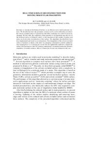
calculated all the coefficients, which ensures the lossless image compression. The method efficiency for natural images was compared with JPEG (Microsoft Photo Editor) – one of the most famous tools for image processing. The comparison results showed that the behavior of the new method for grayscale and color natural images is similar with that of JPEG and for this reason these results are not included in the paper. The method offers better results for very high compression (compression ratio above 100) of natural color images only. The performance of the new method is significantly better when graphic and text images are processed. For the comparison were used more than 100 graphic and text images (grayscale and color). The compared formats were vsd, tga, jp2 and tiff. In Fig. 2 is presented one of the used example grayscale images – a block diagram. The image size is 469x977 pixels.
with Lempel-Ziv. For the investigation the original vsg image was transformed in bmp format. TABLE 1
RESULTS FOR FILE SIZE OF FIG.1.
Vsd [kB] 68
Bmp [kB] 452
TgaRLE TiffLZW JPEG2000 [kB] [kB] [kB] 40 20 48,0
TK [kB] 11,0
In Table 2 is presented the evaluation of the method efficiency, using the compressed file size. If the TK method efficiency is assumed to be 1, the efficiency of all other methods is much lower. The comparison results for pdf files are similar. TABLE 2
RESULTS OF THE TK METHOD EFFICIENCY FOR FIG.1. TK 1
Vsd 0,16
TiffLZW 0,55
TgaRLE 0,28
JPEG2000 0,227
In Table 3 is given the size (in pixels) of 8 of the tested (bmp) images, used for the method evaluation. TABLE 3 SIZE OF THE EXAMPLE TEST IMAGES IN PIXELS
Image
Fig.1
Fig.2
Fig.3
Fig.4
Size 469x977 524x875 606x954 423x726 (pixels) Image
Fig.5
Fig.6
Fig.7
Fig.8
Size 730x1001 521x935 716x974 423x724 (pixels) The results for the compression ratio obtained for 8 grayscale test images with the new method (TK) and with the already mentioned formats (JPEG2000, tga, tiff) are presented in Fig.3.
40 30 20 10
JPEG2
TGA
TK
Fig. 3. Compression ratio
TIFF
Fig8
Fig7
Fig6
Fig5
Fig4
Fig3
0 Fig2
In Table 1 are presented the results, obtained after compression of Fig.1 with the lossless formats vsd (Visio), Tga (targa, RLE compression), tiff (LZW compression), JPEG2000 standard (lossless version) and TK (the presented new method). The size of the corresponding bmp image is included for illustration only, because it is not compressed. The Tga format was processed with RLE (Run-Length Encoding) and tiff –
50
Fig1
Fig.2. Test image “Block diagram”
Compression Ratio
60
Compressed file size
90 80 70 60 50 40 30 20 10 0
Fi g1 c Fi g2 c Fi g3 c Fi g4 c Fi g5 c Fi g6 c Fi g7 c Fi g8 c
File size [KB]
The comparison of the compressed files size is presented in Fig.4. The compressed TK file is the smallest for all tested images.
Fig1 Fig2 Fig3 Fig4 Fig5 Fig6 Fig7 Fig8 Visio
TGA
TIFF
JPEG
VSD
JPEG2
TIFF
TGA
TK
TK
Fig. 6. Compressed File size for colour graphics Fig. 4. Compressed file size (grayscale images)
Similar tests were performed for color graphic images (24 bpp). In this case the IDP decomposition is performed in similar way, but three different pyramids are build – one for each color component.
100 90 80 70 60 50 40 30 20 10 0
Fi g1 c Fi g2 c Fi g3 c Fi g4 c Fi g5 c Fi g6 c Fi g7 c Fi g8 c
Compression Ratio
In Fig.5 are presented the results for the obtained compression ratio for the example images, and in Fig.6 – the corresponding compressed files size. In both cases the TK compression is the most efficient.
The results, obtained for text images, are similar. In Fig.7.a is presented a greyscale text image with size 256x256 pixels after lossless TK compression with compression ratio 17. In Fig.7.b is presented the same image after JPEG2000 compression with same compression ratio (17) - the image processed with JPEG2000 is highly deteriorated. The compression ratio obtained for this image with lossless JPEG2000 (LuraTech Algovision) was only 1,89. Similar (and very close) results were obtained for the other tested grayscale text images.
TIFF
TGA
TK
JPEG2
Fig. 5. Compression ratio for colour graphics
Fig.7.a. Image restored after lossless TK compression (Compression ratio 17)
- Compression of biometric information (fingerprints and voice), which to be used for reliable user identification. The future development of the method should be performed in the following directions: - Lossless intra-frame compression applications for computer games, etc.
with
- The method efficiency could be further enhanced with the use of arithmetic coding for the IDP data. V.
ACKNOWLEDGEMENT
Fig.7.b. After compression with JPEG2000 (Compression ratio 17)
This work was supported by the Ministry of Education and Science of Bulgaria (contr. VU-MI-104).
IV. CONCLUSION
REFERENCES
The main advantages of the new method, which are confirmed with the obtained experimental results, are: - The efficiency of the method for lossless compression of graphics and texts is higher than that of JPEG2000; - The computational complexity of the method is lower than that of the standards JPEG and JPEG2000, because it is based on the WHT and on data histogram analysis [7]. - The method is suitable for Internet applications, because its structure permits the information to be transferred sequentially, with increasing resolution, in accordance with the IDP decomposition levels. The data transfer could be stopped when sufficient resolution (or image quality) is obtained. The software implementation of the method, named TKView (C++, Windows environment) proved its suitability for multiple applications: distance learning, training, technical services, etc. The basic possible application areas of the new image compression method are: - Distance learning. (The efficient image compression permits the learning information to be easily accessible via Internet). - Digital libraries; - Processing of fax data; - Compression of contour images. This application is of great importance for processing of schemes, games, cartoons, etc. - Compression of some kinds of medical information (for example, electro cardiograms or other kinds of medical graphics);
[1] W. Pennebaker, J. Mitchell. JPEG still image data compression standard. Chapman&Hall, NY 1993. [2] T. Acharya, P. Tsai. JPEG 2000 standard for image compression: concepts, algorithms and VLSI architectures. J. Wiley & sons. NJ, 2005. [3] M. Antonini, M. Barlaud, P. Mathieu, I. Daubechies. Image Coding using Wavelet Transform. IEEE Trans. on Image Processing, Vol. 1, No.2, April 1992, pp. 205-220. [4] M. Adams, F. Kossentini. Reversible Integer-to-Integer Wavelet Transform for Image Compression: Performance Evaluation and Analysis. IEEE Trans. on Image Processing, Vol.9, June 2000, pp. 1010-1024. [5] T. Acharya, J. Jaja. An On-line Variable Run-Length Binary Encoding of Text. Information Sciences, Vol. 94, 1996, pp. 1-22. [6] J. Ziv, A. Lempel. Compression of Individual Sequences via Variable-Rate Coding. IEEE Trans. on Information Theory, IT-24, Vol.5, September 1978, pp. 530-536. [7] R. Kountchev, M, Milanova, C. Ford, R. Kountcheva. Multi-layer Image Transmission with Inverse Pyramidal Decomposition. In “Computational Intelligence for Modelling and Predictions”, S. Halgamuge, L. Wang (Eds.), Vol. 2, Chapter No 13, pp. 179–196, SpringerVerlag Berlin Heidelberg, 2005. [8] R. Kountchev, Milanova M., Ford C., Todorov Vl., Kountcheva R. Detection and Lossless Compression of Texts and Graphics in Compound Images. International Symposium on Innovations in Intelligent Sysems and Applications (INISTA, 2005), June 15-18, 2005, Istanbul, Turkey, pp.1-4.