November 15, 2006 / Vol. 31, No. 22 / OPTICS LETTERS
3363
Efficient reflection grisms for pulse compression and dispersion compensation of femtosecond pulses Emily A. Gibson, David M. Gaudiosi, Henry C. Kapteyn, and Ralph Jimenez JILA, Department of Physics and Department of Chemistry and Biochemistry, University of Colorado, and National Institute of Standards and Technology, Boulder, Colorado 80309
Steve Kane Horiba Jobin-Yvon, Edison, New Jersey 08820
Rachel Huff, Charles Durfee, and Jeff Squier Department of Physics, Colorado School of Mines, Golden, Colorado 80401 Received June 30, 2006; revised August 25, 2006; accepted August 30, 2006; posted August 31, 2006 (Doc. ID 72440); published October 26, 2006 Efficient reflection grisms for pulse-compression and material-dispersion compensation have been designed and demonstrated in a 40 fs, 300 J, 5 kHz downchirped pulse amplification system for the first time to our knowledge. A grism design for 800 nm femtosecond laser pulse dispersion compensation applications is realized by using standard, commercial diffraction gratings. © 2006 Optical Society of America OCIS codes: 320.0320, 320.5520, 320.5540.
In the earliest demonstrations of chirped pulse amplification (CPA), the compressed pulse duration was limited by dispersion mismatch between the fiber stretcher and the Treacy grating-pair compressor.1 Specifically, the fiber dispersion was nearly linear, with positive group-velocity dispersion (GVD) and positive third-order dispersion (TOD), while the grating-pair compressor dispersion provided negative GVD and a significant amount of positive TOD. With the introduction of the grating-pair stretcher,2 the dispersion mismatch between optical-material stretchers and grating-pair compressors was no longer an issue for high-power CPA systems.3 There are, however, many applications that would benefit from the ability to compensate for large amounts of material dispersion. The optical fiber delivery of femtosecond laser pulses is one example. Currently this requires complicated prism sequences to partially compensate for excess TOD from the large material dispersion of the fiber. Also, femtosecond laser amplifier systems could be greatly simplified by replacing the grating-pair stretcher with optical glass or, for submillijoule systems, by using the material in the amplifier to stretch the pulse. In this Letter we present a practical solution for compensating large amounts of material dispersion by demonstrating what we believe to be the first reflective, broad-bandwidth grisms (gratings in optical contact with a prism) suitable for tunable and broadband femtosecond laser applications. The grism design relies on the fact that for most materials the ratio of GVD to TOD is nearly constant; therefore a pulse can be compressed after passing through any amount of material by simply adjusting the separation of the grism pair. The grism pair is used as a pulse stretcher in a multikilohertz, femtosecond Ti:sapphire amplifier system. The amplified pulses are compressed to a final pulse width of 40 fs by sim0146-9592/06/223363-3/$15.00
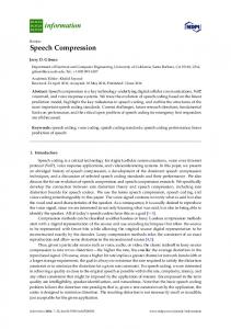
ply passing the output of the amplifier through a block of glass. Tournois showed that a conventional grating-pair compressor could never be designed with pure GVD and zero TOD4; however, a compressor made from grisms could satisfy the condition for zero-TOD operation. Kane and Squier expanded upon this design, showing that grisms could exhibit negative GVD and negative TOD,5,6 and a 600 lines/ mm grism was fabricated to compress an 800 nm, 135 fs pulse that had propagated through over 100 m of optical fiber, in the first (to our knowledge) demonstration of a grismcompressor design. However, these early grisms were impractical because they were very inefficient (⬍25% per pass). For a grism to be most efficient 共80% – 90% 兲, the grating should satisfy the Littrow condition; i.e., the angle between the incident beam and diffracted beam should be nearly zero. To satisfy the zero-TOD or negative-TOD requirement of the compressor, the grism described by Tournois must have an extremely large deviation angle, of the order of 90°, and therefore is not a good candidate for a high-efficiency component. The goal of this new study was to design a grism that would satisfy the negative-TOD requirement and operate near Littrow to provide high efficiency. The design of the new reflection grisms is shown in Fig. 1. The beam is incident on the prism and diffracts from the grating inside the prism material, but unlike the Tournois grism, the beam is then refracted at a surface that is not parallel to the grating surface. At this prism surface, the angular dispersion is sin d = n sin兵p + arcsin关sin共i − / nd兲兴其, where p is the prism angle, i and d are, respectively, the incident and diffracted angles, is the wavelength, and n is the refractive index of the prism material. This slight modification to the grism geometry provides a new degree of design freedom. By selecting the right © 2006 Optical Society of America
3364
OPTICS LETTERS / Vol. 31, No. 22 / November 15, 2006
Fig. 1. Schematic of the new efficient broad-bandwidth reflection grisms for (a) normal incidence and (b) Brewster’s angle incidence.
combination of grating groove density and prism angle p, it is now possible to specify a Littrow-use grating that is highly efficient at the grism’s design wavelength and simultaneously satisfies the negative-TOD condition. In addition, refraction at the prism surface increases the angular dispersion, thereby increasing the effective grating groove density by up to a factor of 2. The GVD and TOD of this new design are not characterized by simple expressions (as in the case of a Treacy compressor or a Tournois compressor using conventional grisms); however, the dispersion is straightforwardly calculated by ray tracing or by direct calculation of the phase. We designed and fabricated a pair of reflection grisms for operation at 800 nm, normal incidence. These grisms are constructed of 600 lines/ mm goldcoated ruled gratings 共50 mm⫻ 140 mm兲 and antireflection-coated 26° prisms (N-BAK4 glass). For negative-TOD operation, the deviation angle of the grism is approximately 30°, sufficiently close to Littrow for high efficiency. The measured efficiency for a single pass in one grism over 750– 850 nm is 70% – 80%, while the efficiency of the entire grism pair compressor is 25% – 30%. While this efficiency is adequate for many ultrafast applications, higher efficiencies of ⬎90% can be achieved with optimized pulse-compression gratings. Previous work by Kane and Squier5 showed that the ratio of TOD/GVD for most common optical materials is nearly equal at 800 nm and can be compensated by using a grism pair. For most optical materials, this ratio is ⬃0.73, and the grism compressor is designed with the same ratio but opposite sign. In addition, the ratio of TOD/GVD is nearly constant as a function of separation so that any amount of material can be compensated up to third order by simply adjusting the separation. Fine-tuning of TOD/GVD can be achieved by slight adjustment to the incident angle of the grisms. Changing the incident angle over a range of 4° can continuously tune the ratio from 1.0 to 0. Fourth-order dispersion (FOD) of common materials is quite low compared with the GVD and TOD, so a grism-material combination will always have residual FOD from the grisms. This residual FOD, which can be partially compensated with oppositesign GVD, will limit the pulse durations that can be achieved with a grism-material system as discussed in greater detail in Ref. 5.
As a demonstration of the ability to compensate for material dispersion, the 800 nm grism pair was used to compress 40 fs pulses in a multikilohertz Ti:sapphire amplifier system. The amplifier design, shown in Fig. 2, is based on the downchirped pulse amplification scheme demonstrated by Gaudiosi et al.7,8 The output of a cavity-dumped Ti:sapphire oscillator (cavity dumped at 5 kHz) is directed through the grism pair to stretch the pulse to around 12 ps duration prior to amplification. In this case, the grism pair is used as a stretcher that imparts negative chirp to the pulse, while traditional CPA uses a grating stretcher to positively chirp the pulse. The grism stretcher has several advantages over the traditional grating stretcher design. First, it is not complicated through the addition of lenses or mirrors, which can be difficult to align and lead to spatial chirp. In contrast, the grisms are extremely easy to align, with the beam at normal incidence to the prism face. Second, the entire stretcher is extremely compact: a separation of only 2.8 cm stretches the pulse to 12 ps. Finally, simultaneous GVD and TOD compensation of most materials is accomplished simply by adjusting the separation of the grism pair. Figure 3 shows the measured spectra from the oscillator, after the grism stretcher, and after amplification. There is moderate reshaping, but there is no spectral clipping from the stretcher. Notably, the bandwidth is 110 nm (FWHM) after the grism pair. After stretching, the pulses are amplified by a cryogenically cooled, Q-switched YAG-pumped multipass Ti:sapphire amplifier system at 5 kHz. The pulses are amplified to 300 J per pulse. The amplified spectrum is narrower (35 mm, FWHM) and shifted to shorter wavelengths because of the wavelengthdependent gain of the Ti:sapphire crystal at 50 K. The amplified, chirped pulses are recompressed by simply passing the beam through 1 m of SF18 glass. The amplifier output is first spatially filtered through a pinhole (95% transmission) and expanded by a telescope to a beam diameter of 2 cm (1 / e2 intensity) to minimize nonlinear effects. The beam is then passed multiple times through two blocks of SF18 glass (1 m total path length). The calculated B-integral of the pulse after propagation through the compressor is 0.4. Also, the spectra after the amplifier and after the glass compressor are identical, indicating the absence of nonlinear effects. In general, glass compres-
Fig. 2. (Color online) Downchirped pulse Ti:sapphire amplifier system layout with grism stretcher and glass compressor.
November 15, 2006 / Vol. 31, No. 22 / OPTICS LETTERS
Fig. 3. Pulse spectrum evolution through the amplifier: directly from the oscillator (solid curve), after the grism pair stretcher (dotted curve), and after amplification (dashed curve).
Fig. 4. (Color online) Amplified pulse after glass compressor: (a) reconstructed spectrum and spectral phase; (b) reconstructed temporal profile of the pulse intensity.
sion does not limit the potential pulse energy or bandwidth of the amplifier as the beam size can be increased to maintain a low B-integral. Compression through the last 10% of the material length, where the pulse is shortest, contributes most to the B-integral (⬃63% for our conditions). Therefore it is more critical to expand the beam during the final pass through the glass. The same issue arises when using the grism pair as a compressor, as the beam must be expanded to reduce the nonlinear phase from the last pass through the grism-glass material. The calculated dispersion at 775 nm (the center wavelength of our amplifier) provided by our grism stretcher for normal-incidence geometry and 2.8 cm separation is −1.766E5 fs2 GVD and −1.115E5 fs3 TOD. The ratio of TOD/GVD is 0.631 and is lower than the design ratio because for our grism-pair separation, the path length through glass was larger than that through the air space. At larger separations, the grism pair has a constant TOD/GVD ratio with separation of 0.73. Future grism stretcher designs will employ smaller dimension grisms so that the path length through the glass is minimized, achieving a constant TOD/GVD ratio with separation even at small separations. The dispersion from the material in our amplifier system (1 m SF18 glass, 1 cm BK7, 5.4 cm Ti:sapphire) at 775 nm is calculated to be 1.65E5 fs2 GVD and 1.01E5 fs3 TOD. The ratio
3365
of TOD/GVD is 0.61, dominated by the dispersion of the SF18 glass. The magnitude of material dispersion is in excellent agreement with the calculated dispersion of the grism stretcher. Note that our calculation is an underestimate because there is additional dispersion from the Bragg cell. The pulse after compression was measured experimentally with a Grenouille-frequency-resolved optical grating. The frequency-resolved optical grating measurements were deconvolved by using commercial software to an error of ⬍3% 共128⫻ 128 grid兲. Figure 4(a) shows the reconstructed spectrum and spectral phase, and Fig. 4(b) shows the reconstructed intensity envelope in time. The compressed pulse has a flat-phase profile over the entire spectrum, giving a pulsewidth of 40 fs. Currently, the overall efficiency of the compressor is around 50% – 60%, including spatial filter; however with antireflection coating on the glass, it will be straightforward to achieve efficiencies of greater than 90%. In conclusion, efficient reflection grisms with applications for broad-bandwidth femtosecond pulse dispersion compensation have been designed, fabricated, and implemented for the first time to our knowledge. Standard commercial gratings have been used to construct grisms for 800 nm wavelength applications. These grisms have been used for the first time to our knowledge in a simple, compact, and efficient pulse compression design for a Ti:sapphire amplifier system, producing 40 fs, 300 J pulses at 5 kHz. This work was partially supported by the National Science Foundation under grants MRI PHY04203457 and PHY-096822 and the NIBIB under grant EB003832. R. Jimenez is a staff member of the Quantum Physics Division of National Institute of Standards and Technology. E. A. Gibson (
[email protected]) is supported by an NRC postdoctoral fellowship. References 1. D. Strickland and G. Mourou, Opt. Commun. 56, 219 (1985). 2. M. Pessot, P. Maine, and G. Mourou, Opt. Commun. 62, 419 (1988). 3. P. Maine, D. Strickland, P. Bado, M. Pessot, and G. Mourou, IEEE J. Quantum Electron. 24, 398 (1988). 4. P. Tournois, Electron. Lett. 29, 1414 (1993). 5. S. Kane and J. Squier, IEEE J. Quantum Electron. 31, 2052 (1995). 6. S. Kane and J. Squier, J. Opt. Soc. Am. B 14, 661 (1997). 7. D. M. Gaudiosi, E. Gagnon, A. L. Lytle, J. L. Fiore, E. A. Gibson, S. Kane, J. Squier, M. M. Murnane, H. C. Kapteyn, R. Jimenez, and S. Backus, “Scalable multikilohertz repetition rate Ti:sapphire amplifier based on down-chirped pulse amplification,” submitted to Opt. Express. 8. D. M. Gaudiosi, A. L. Lytle, P. Kohl, M. M. Murnane, H. C. Kapteyn, and S. Backus, Opt. Lett. 29, 2665 (2004).