EFFICIENT IMAGE DATA PROCESSING BASED ON AN AIRBORNE DISTRIBUTED SYSTEM ARCHITECTURE O. Meynberg, D. Rosenbaum, F. Kurz, J. Leitloff, U. Thomas German Aerospace Center (DLR), Remote Sensing Technology Institute, PO Box 1116, D-82230 Weling, Germany
[email protected] Commission I/2 KEY WORDS: Interprocess Communication, Shared Memory, Orthorectification, Tracking, Message Passing
ABSTRACT: This paper examines and describes improvements of the processing time of an airborne wide area monitoring system which is under development at the German Aerospace Center (DLR). Aboard the aircraft a computer network equipped with three off-the-shelf cameras acquires images at intervals of up to 3fps. After orthorectification a traffic processor runs an automatic road traffic-data extraction and sends its result to a receiving ground station via an S-Band radio link. The processed results must be available as fast as possible. Hence, processing times of the computationally intensive tasks are meassured. In this context it turned out to consider not only the pure processing times but also the copy operations of the images between the modules. We compare several interprocess communication mechanisms and discuss the results. With the usage of relatively simple shared memory concepts a significant speed-up can be reached. 1
INTRODUCTION
During mass events or natural disasters security authorities and emergency services are dependent on precise and up-to-date information about the operational area. Since under such extreme conditions the scenario can change completely every couple of minutes the current traffic situation and the condition of motorways are of special interest. The command centers demand for both a detailed and an up-to-date overview of the area. However, stationary sensors like inductive loops, radar sensors or terrestrial traffic cameras have a poor spatail resolution whereas street maps have a low temporal resolution, i.e. they might be simply out of date. Moreover in cases of natural disaster a traffic monitoring system should not only depend on an intact infrastructure. Therefore the German Aerospace Center (DLR) develops an airborne wide-area monitoring system, which is able to transmit high-resolution optical images and traffic data of the affected area in near real time to the ground. This system is mounted aboard an airplane and consists of the DLR 3K-camera system (Kurz et al., 2007), a processing rack and a slave tracking antenna. The automatic onboard analysis including orhtorectification, georeferencing and road-traffic data extraction demand high standards to the onboard hardware/software system. Three cameras produce images at a data rate of up to 54 MB/s. To cope with this large data rate each camera is dedicated to one computer. After orthorectification the images are forwarded to the vehicle detection and tracking processor (Rosenbaum et al., 2008), which runs on a fourth computer. Those two processes are computationally intensive tasks and should be responsible for the lion’s share of the processing time. Nevertheless all steps in the processing chain perform read and write operations, copy the data into main memory or send it via Ethernet to another host, which sums up to a considerable amount of the processing time. Therefore this paper investigates the processing chain and tries to reveal bottle necks and data congestions in order to optimize the overall processing time. The faster it is the more data can be sent early enough to the user on the ground. At first the processing system is described in chapter 2. The focus of chapter 3 lies on the data exchange between processes. Its methods and its influence on performance are examined in chapter 4. Chapter 5 gives an outlook on further improvements.
2
ONBOARD PROCESSING SYSTEM
One of the biggest benefits of the airborne monitoring system is the provision of quasi-live traffic data. But to allow detecting and tracking of vehicles some preparatory steps must be performed which are described in the following. Thereafter the traffic monitoring itself is described. 2.1
Image Acquisition and Orthorectification
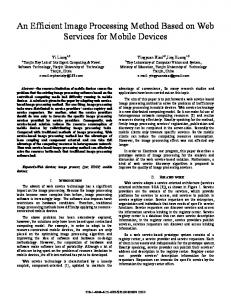
The 3K-camera system consists of three non-metric Canon EOS 1Ds Mark II mounted on a ZEISS aerial platform. One looks in nadir direction and two look in oblique sideward direction resulting in an increased FOV of up to a max. angle of 110 degree / 31 degree in track/flight direction. The cameras operate at an acquisition rate of up to 3Hz to enable automatic vehicle tracking. With an image size of 4992 · 3328 pixels and a color depth of 24 bits the overall output data rate of the camera system is 3.5 GBit/s ≈ 428 M Byte/s. With JPEG compression within the cameras this data rate can be reduced to 54 MByte/s assuming an average image size of about 6 MByte per image. This high input data rate on the one hand and the processing intensive modules on the other hand put high demands on the on-board image processing hardware, which consequently leads to a multi-host solution with five PCs in total (Fig 1). All of them run 32bitWindows XP due to the fact that some of the third-party software we use in our processing system only supports Windows. Each camera is connected via Firewire IEEE 1394a to a dedicated host. It streams the images directly without memory-card buffering to the camera PCs (PC1 - PC3). The EOS Digital Camera Software Development Kit (EDSDK) is installed on each of these hosts and provides a C language interface for controlling connected cameras and downloading images to the host PC. Supported operating systems are Microsoft Windows 2000 or higher and Mac OS X since version 10.4. The camera PCs have an identical hardware setup as shown in Fig. 1 and Table 1. Since the orthorectification and georeferencing process needs the exact position and orientation of the airplane IGI’s AEROcontrol, a GPS/IMU system, is connected via Ethernet to the onboard system. The fibre-optic gyro based Inertial Meassurement Unit and the AEROcontrol with its integrated 12-channel L1/L2 GPS receiver are triggered by the Mark II’s external flash signal (Fig. 2). Every
Proprietary S-band downlink Data rate: ~10Mbit/s
External Flash Signal Camera Firewire
PC1
IMU
PC5
PC2
PC4
Firewire (IEEE 1394a)
PC3 Gigabit Ethernet IEEE 802.3ab
Technical Data of ARGOS machines CPU: Intel Core 2 Duo 3GHz or Core 2 Quad 2.6 GHz RAM: 2 Gbyte Graphics card: NVIDIA GeForce 9800 GTX
DGPS Receiver
Figure 1: Topology of the onboard network. Each camera is directly connected to PC1,2,3 which perform georeferencing and orthorectification. Vehicle tracking takes place on PC4. PC5 sends the results via a proprietary S-band transmitter to the ground. time a flash signal is received the AEROControl sends coordinates and orientation via a TCP connection to one of the camera PCs. The camera module runs a TCP client and matches the received geo-data with the image received from the camera. The image is written to disk where it can be read in by the Ortho Module. The geo data is sent to the Ortho Module via message passing. After the orthorectification process itself, which is described in detail in (Mueller et al., 2002), has completed, it writes the orthorectified image to disk and does not keep it in main memory. 2.2
Traffic Monitoring
For traffic monitoring aerial images are recorded in a special mode called burst mode. Each image burst consists of 3-5 images taken with a high repetition rate of up to 3 Hz. In order to keep the data amount as low as possible, no image data is recorded between to bursts. Within this break the plane moves over the ground, until a new region is in sight the field of view of the cameras. A typical break lies between 5-7 seconds depending on flight height and airspeed. For automatic traffic data extraction each image burst is processed separately. Processing starts with vehicle detection on the first image of each image sequence (burst) followed by a vehicle tracking based on template matching between the image pair consisting of the first and second image of the sequence. With this strategy the traffic parameters flux and density can be derived from aerial image sequences. Vehicle detection performed on the first georeferenced image of the sequence gives the vehicle density whereas vehicle tracking applied on all consecutive (georeferenced) image pairs gives the velocity of the vehicles so that the flux of the traffic can be calculated. Vehicle detection is performed by the application of two classifiers to the first image of each sequence with the use of a priori knowledge of the rough position of the roads inside the image obtained from a road database. The classifiers are based on the algorithms AdaBoost and SVM and were trained offline by a training dataset consisting of (aerial) thumb images of 3000 vehicles and more than 10000 negative examples. We obtain a classification quality of more than 80 % even in complex scenarios like downtown areas. Vehicle tracking between two consecutive images of the burst is done by template matching based on normalized cross correlation. At each position of a detected vehicle in the first image of
Gigabit Ethernet
Figure 2: Each Camera Module on PC 1,2 and 3 gets coordinates and orientation from a DGPS receiver and an IMU. Every time the camera fires it triggers the DGPS receiver to send the geo data of the projection center of this point in time to the Camera Module. the image sequence a template image is created. Then in the second image of the sequence a search space for this vehicle is generated depending on the position of the vehicle in the first image, driving direction obtained from a road database, and the expected maximum speed for the road plus a certain tolerance. Within that search space, the template is correlated and the maximum correlation score is stored in connection with the template position within the maximum appeared. This represents the found match of each vehicle in generally. The correlation is done in RGBcolor space. Since all images are stored with their recording time, vehicle speed can directly calculated from both the position of the vehicle detected in the first image and the position of the corresponding match in the second image. Then, vehicle tracking is applied to the following image pair of the sequence. Vehicle tracking performs well with a quality of 90-95 %. The processing chain of the traffic software prototype is built up modular, since all modules were built as self-contained programs. 3
INTERPROCESS COMMUNICATION
Until now nothing has been said about how the modules exchange data. The current version of our onboard processing system transfers images between modules just by writing and reading them to/from hard disk. This simple and easy-to-implement mechanism might not be the ideal solution in terms of access times and transfer rates but has in the age of multi-terabyte drives a nearly infinite buffer size. Nevertheless this paper wants to investigate alternative Interprocess Communication mechanisms (IPC) because as described in Cha. 1 time is the crucial point in our scenario. Windows provides nine mechanisms for facilitating IPC. A comprehensive overview of these mechanisms gives (MSDN, 2010b). Since we have several hosts connected via Gigabit Ethernet, the IPC mechanism must support processes running on different hosts. Clipboard and its extension Data Copy do not have network support. Microsofts Distributed Component Object Model (DCOM) and CORBA - both widely used middlewares for
Complete image
Image 1
Image 2
Image 3
allocation granularity which is usually 65536 bytes. 3.2
Inter-Host Data Exchange
Vehicle suroundings
To get the orthorectified images from the Ortho Module to the Traffic Processor we use Server Message Block (SMB). In this case, however, the Ortho Module writes the images to the camera PC’s disk and the Traffic Processor has to load it into RAM again before processing can begin. This could be avoided with a direct RAM-to-RAM transfer from a camera PC to PC4.
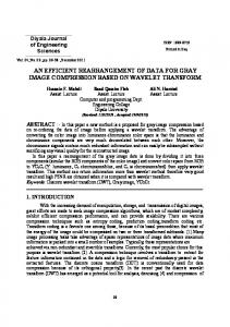
Vehicle Detection
4 Road Database
Vehicle Tracking Image 1 and 2
Vehicle Tracking Image 2 and 3
Figure 3: The Traffic Processor needs three consecutive images to track vehicles in orthorectified images. The Vehicle detection reads in the first image and searches for vehicles with the help of a road database. For tracking the second image is loaded. The third image is used for the second car tracking iteration.
The focus of the following tests is on timing performance as well as on the detection of data pile-ups between the image processes of the on-board network. 4.1
3.1
Canon EOS 1Ds Mark II Full frame CMOS sensor 24x36mm Canon EF 50mm Intel Core 2 Duo E8400 @ 3GHz 2.0 GByte Intel PRO/1000 GT Desktop Adapter Nvidia GeForce 9800 GTX,512 MB Seagate Barracuda ST31000340NS EDSDK v2.6 MS Windows XP Prof. Ver. 5.1.2600 SP3 Visual C++ 9.0.2
Table 1: Test setup: All PCs in this test have an identical hardware setup except of PC4 which is equipped with an Intel Core 2 Quad 2.6 GHz CPU. To measure the time on Windows operated machines as accurately as possible we use the built-in “High-Resolution Timer” of the Windows-API (MSDN, 2010a). This is done by mainly calling the following two functions in our test programs:
Intra-Host Data Exchange
The Windows File Mapping concept enables processes to share images by passing pointers, but it only works if the processes reside on the same host. It is used to transfer images from the CameraModule to the OrthoModule (2). The Windows-API provides the FileMapping concept to create a memory, which can be shared with other processes on the same host. At first the function CreateFileMapping() called with a unique characterbased string creates a file mapping object. This object is used to call the function MapViewOfFile() which returns a pointer to the first byte of the newly mapped address space. This pointer can be used to copy data into this shared memory (e.g. by using memcpy()). All other processes on the same host firstly open the shared memory by calling OpenFileMapping() and secondly by calling also MapViewOfFile(). The second process must ensure that OpenFileMapping() is called with the same characterbased string as only already created file mapping objects can be opened with this function and this character-based string serves as the object’s system-wide ID. To subdivide this shared address space into local pages MapViewOfFile() is called with the parameter dwFileOffset. Also the size of this mapped view can be specified. With these parameters it is possible to make a part of the shared memory available to the address space of the calling process. The file offset must be a multiple of the system’s
Test Setup and Methods Camera Model Sensor Lens Hardware CPU RAM Network Video HDD Software Camera API OS Compiler
large distributed systems - can be compared in terms of complexity, timing and functionality and are not appropriate for our rather small system. Dynamic Data Exchange (DDE) is considered to be not as efficient as newer technologies and therefore can be excluded as well. Mailslots and anonymous pipes only provide one-way communication. Named Pipes provide all the necessary functionality but each pipe client opens one thread, which should be avoided. Other mechanisms like I/O Completion Ports provide better performance through better thread management (Richter and Nasarre, 2007). Windows Sockets and File Mapping, however, are a good solution. The Winsock-API provides simple functions to transfer messages between processes, regardless of whether they run on the same host or not. This messages are for the exchange of administrative data like coordinates or orientation angles. We are also going to meassure transfer and processing times of these messages but the main problem is the exchange of the large images between the processes.
RESULTS AND DISCUSSION
BOOL QueryPerformanceFrequency (LARGE_INTEGER *lpFrequency); BOOL QueryPerformanceCounter (LARGE_INTEGER *lpPerformanceCount);
Initially the function QueryPerformanceFrequency() must be called to determine if the system supports a high resolution counter. If it does, the pointer lpFrequency points to a variable that receives the counter frequency in counts per second, otherwise the bool-return value is zero. Most often the counter’s frequency is equal to the CPUs clock rate. Every time the function QueryPerformanceCounter() is called the variablelpPerformanceCount receives a pointer to a 64-bit signed integer value, which represents the absolute number of counts since the systems startup. Now it is possible to calculate the difference between two subsequent calls and convert it to milliseconds. 4.2
Chronological Analysis
The drawn-through zig-zag line in Fig. 4 shows the time it takes to orthorectify an image with a spatial resolution of 20 cm. Read/write operations from/to disk are not included in this first measurement. With an average processing time of about 12s it accounts for the major part of the overall processing time of the Ortho Module. The second measurement (dashed line) represents
orthorectification write image to disk write image to RAM Amount of data [MBytes]
Processing time [seconds]
17 16 15 14 13 12 11 10 9 8 7 6 5 4 3 2 1 0 0
10 20 30 40 50 60 70 80 90 100 110 120 130 140 150 Number of taken images
Figure 4: The first line shows the processing time without read and write operations. The second line represents the absolut time it takes to write one orthorecitified image to disk. The third line at the bottom represents the same write operation except the fact that it is written to RAM.
800 750 700 650 600 550 500 450 400 350 300 250 200 150 100 50 0
camera output ortho left ortho nadir
0
25
50
75 100 125 Time [seconds]
150
175
200
Figure 6: The first line shows the absolut amount of data the Camera Module produces as a function of time. The second and third line shows the absolut amount of data which the Ortho Module has already read into its process memory. The differences of line 1 and 2 and of line 1 and 3 respectively show the amount of data the ortho module has not processed yet.
40 traffic processing time 4000
25 20 15 10 5
3000 2500 2000 1500 1000 500
0 0
10 20 30 40 50 60 70 80 90 100 110 120 130 140 150 Image index number
Figure 5: The processing time of the traffic processor varies between 10 and 33 seconds - depending on the number of streets and vehicles in the processed image. the write operations for every image of the test sequence. On average it takes 2 seconds to write an orthorectified 200-Mbyte image to disk which means that the hard disk access time consumes 14 % of the overall orthorectification processing time. The next interesting step is the Traffic Processor. Its processing times per image are shown in Fig. 5. They vary widely between 10 and over 30 seconds. This is due to the fact that the input image also varies in number of streets and vehicles. If almost no motorways are on an image vehicle detection and tracking can be completed much faster or sometimes even skipped which results in lower processing times. As shown in Fig. 3 the image is read into memory three times if the complete tracking algorithm is applied. Then the processing time reaches its absolute maximum of 34 seconds (Fig. 5). Read operations from hard disk need six seconds or 17 % of this time. 4.3
ortho process output traffic process output
3500
30 Amount of data [MBytes]
Processing time [seconds]
35
Shared Memory Environment
As we stated earlier the overall processing time must be leveled down as low as possible in order to transfer more images to the ground. To reduce the transfer time between Ortho Module and Traffic Processor these two modules can exchange images via a shared section in main memory (see also Cha. 3.1). With this method the relatively slow access times of hard disks can be
0 0
10 20 30 40 50 60 70 80 90 100 110 120 130 140 150 Time [seconds]
Figure 7: Similar to Fig. 6 this diagramm shows the amount of data which is processed by the Ortho Module but not by the Traffic Processor. avoided. The third graph in Fig. 4, which is labeled “write image to RAM”, shows the time it takes to write the orthorectified images to main memory and not to hard disk. These images with a size of about 200 Mbyte are written in 0.16 seconds to RAM, that is 14 times faster than the transfer to hard disk. During a typical flight campaign we shoot at least 100 images in burst mode per camera. If the images were not written to disk but to RAM the gain in time would sum up to over three minutes until the end of the campaign. 4.4
Amount of Data between Modules
For further investigation we now focus on the amount of data which must be buffered between each processing step. This must be done when migrating large amounts of memory from disk to RAM because of the RAM’s much smaller size. We can simply run out of memory if the Camera Module’s output data rate is much higher than the Ortho Module’s input data rate (Fig. 6). Because of the relatively fast acquisition of the camera and the comparatively slow orthorectification process the amount of data between the modules piles up to over 500 Mbytes until the end of a flight campaign. These 500 Mbytes are JPEG images, RAW images would naturally produce a much higher amount.
Another test should show the data pile-up between Ortho Module and Traffic Processor and implies that - unlike in Fig. 2 - both modules run on the same host. It is the same scenario as the one in Fig. 6 except that it is one step further in the processing chain. The main difference is the ratio between the processing times. On the one hand Ortho Module and Traffic Profcessor both need several seconds for one image whereas the Camera Module produces the images almost immediately, on the other hand these orthorectified images are much larger than the compressed JPEGs, they need 200 Mbyte of memory instead of 5 Mbyte. Slight differences between processing times can quickly lead to large data pile-ups infront of the Trafic Processor which exceed the size of the host’s RAM. Fig. 7 shows the result of this test. The outputs of both the Ortho Module and the Traffic Processor climb within a flight campaign towards the 2 GB barrier - the size of the builtin main memory and the maximum address space 32bit-Windows can handle per process. But the crucial point is the difference between these two lines, as all images which have run through the traffic processor can be deleted from memory. After 150 seconds of processing 3 to 4 images (750 Mbytes) are still not processed by the traffic processor. If we consider that the Ortho Module permanently holds a 500-MB digital elevation model in memory, the space for additional images gets scarce. This must be considered when building-up a RAM-based processing chain. 5
CONCLUSIONS AND FUTURE WORK
During a typical flight campaign about 100 images per camera must be acquired, orthorectified, analyzed and partially sent to the ground. In principal this goal can be reached but there are some possibilities for optimization. The Camera Module can only provide images as fast as the cameras can shoot them and the images are buffered in front of the Ortho Module anyway. So the processing time of the Ortho Module and the Traffic Processor have the most potential for a massive speed-up of the system. Another point is the exchange of data via shared memory which can accelerate the overall processing time by three minutes. But it must be taken into account that the size of main memory is limited. As soon as the OS must transfer data to the pagefile, the advantage of the shared memory is gone. The focus of future work lies on the acceleration of the processing times itself. A succesful implementation of improved algorithms could lead to a considerable speed-up. These new implementations should use the help of hardware acceleration to get optimum results. With the help of NVIDIA’s programming interface CUDA the orthorectification could perform much faster on the computer’s video card. Almost no additional hardware is needed which is a big advantage for the relatively fix setup of the onboard processing system. Another maybe additional solution might be Field Programmable Gate Arrays (FPGA). They could not only speed up our processes but could also shrink the dimensions of the processing rack - another advantage for airborne sensors. REFERENCES Kurz, F., Mueller, R., Stephani, M., Reinartz, P. and Schroeder, M., 2007. Calibration of a wide-angle digital camera system for near real time scenarios. MSDN, 2010a. About timers. MSDN, 2010b. Interprocess communications. Mueller, R., Lehner, M., Mueller, R., Reinartz, P., Schroeder, M. and Vollmer, B., 2002. A program for direct georeferencing of airborne and spaceborne line scanner images.
Richter, J. M. and Nasarre, C., 2007. Windows via C/C++. Microsoft Press. Rosenbaum, D., Charmette, B., Kurz, F., Suri, S., Thomas, U. and Reinartz, P., 2008. Automatic traffic monitoring from an airborne wide angle camera system. In: ISPRS 2008 (21. Congress).