ing network with O(jN1+2/j) crosspoints and depth j. Improved versions of Clos net- work due to Cantor [Can71] give a strictly nonblocking network with O(N loga ...
EFFICIENT NONBLOCKING SWITCHING NETWORKS FOR INTERPROCESSOR COMMUNICATIONS IN MULTIPROCESSOR SYSTEMS Fong-Chih Shao and A. Yavuz Oru¸c Electrical Engineering Department and Institute for Advanced Computer Studies College Park, MD 20742
Abstract
In this paper, we explore the possibility of using a nonblocking network with O(N log N ) edges1 (crosspoints) to interconnect the processors of an N -processor system. More specifically, we combine Bassalygo and Pinsker’s implicit design of strictly nonblocking networks with a recent explicit construction of expanders to obtain a strictly nonblocking network with −765.18N + 352.8N log N edges and 2 + log(N/5) depth. We present an efficient parallel algorithm for routing connection requests on this network and implement it on three parallel processor topologies. The implementation on a parallel processor whose processing elements are interconnected as in the Bassalygo-Pinsker network requires O(N log N ) processing elements, O(N log N ) interprocessor links and it takes O(log N ) steps to route any single connection request where each step involves a small number (≈ 72) of bit-level operations. A contracted or folded version of the same implementation reduces the processing element count to O(N ) without increasing the link count or the routing time. Finally, we establish that the same algorithm takes O(log3 N ) steps on a perfect shuffle processor with O(N ) processing ele1
log N means log2 N throughout the paper.
ments. These results substantially improve the crosspoint, depth and routing time complexities of the previously reported strictly nonblocking networks.
1
Introduction
The performance of a multiprocessor system hinges critically on the intercommunication ability of its processors which is often impeded by the bandwidth of the network interconnecting them. The full crossbar network goes a long way to solve the bandwidth problem, but at the expense of O(N 2 ) crosspoints for an N -processor system. What is desirable is a network which functions much like a crossbar but with fewer crosspoints. Such networks have been investigated extensively in communication switching and are commonly referred to as strictly nonblocking networks [Ben65]. Formally, an N × N strictly nonblocking network is a directed acyclic graph with N source vertices, called inputs, and N sink vertices called outputs such that, given any idle input x and idle output y, the network always possesses a path from x to y which does not overlap with any of the paths which might already be established between other inputs and outputs. A number of strictly nonblocking networks comprising fewer than O(N 2 ) crosspoints have been reported in the
literature. The well-known 3-stage Clos network [Clo53] provides a strictly nonblocking network with O(jN 1+2/j ) crosspoints and depth j. Improved versions of Clos network due to Cantor [Can71] give a strictly nonblocking network with O(N loga N ) crosspoints, 2 < a ≤ 3, and O(loga N ) depth. Cantor also provided the first strictly nonblocking network with O(N log2 N ) crosspoints and O(log N ) depth [Can71]. Subsequent to these efforts, Bassalygo and Pinsker [BP74, Bas81] obtained a strictly nonblocking network with O(N log N ) crosspoints and O(log N ) depth. Nonetheless, unlike Clos and Cantor networks, Bassalygo and Pinsker’s network relies on the existence of certain bipartite graphs called extensive graphs. This makes their network implicit or nonconstructive. In this paper, we explore the possibility of explicitly constructing strictly nonblocking networks with O(N log N ) crosspoints, O(log N ) depth and O(log N ) routing time. Here, routing generically refers to establishing and abolishing paths between the idle inputs and idle outputs of a nonblocking network. We differentiate between two specific routing problems. The first routing problem deals with establishing (or abolishing) a path between any idle (or busy) pair of inputs and outputs. The second routing problem deals with establishing (or abolishing) paths between any two or more idle (or busy) pairs of inputs and outputs. We shall refer to these two problems as the single routing assignment problem and multiple routing assignment problem, respectively. Two recent efforts on routing problems in nonblocking networks are worth mentioning here. In [ALM90], Arora et al. reported a greedy algorithm for establishing paths between single and multiple pairs of idle inputs and outputs in Multi-Beneˇs networks. These networks encompass O(N log N ) crosspoints and have O(log N ) depth. Even though Multi-Beneˇs networks meet our objective of constructing efficient nonblocking networks in order of complexity terms, the results reported in [ALM90] have at least two drawbacks. First, MultiBeneˇs networks require expanders with large expansion coefficients in order to have a small constant factor in their routing time complex-
ity. It is stated in [ALM90] that one could generate expanders with large expansion coefficients randomly. However, this assumption makes Multi-Beneˇs networks nonconstructive or implicit in contrast to our requirement that the construction be explicit. The second drawback is that the time complexity of the greedy algorithm described in [ALM90] depends on two key design parameters, namely, the indegree (or out-degree) of each switch node d, and loading factor L. This relation was not spelled out exactly in [ALM90], but the authors pointed out that to reduce the routing time one need to increase L and d. In particular, they stated that, to achieve a routing time of 100 log N , the values of d and L should approximately be 10 and 300, respectively. These parameters affect the constant in the crosspoint complexity of Multi-Beneˇs networks. More specifically, when d = 10 and L = 300 constructing a Multi-Beneˇs network requires 240, 000N log N crosspoints. More recently, Lin and Pippenger [LP91] reported both deterministic and nondeterministic path selection algorithms for a strictly nonblocking network which resembles Cantor’s network. Not only that their network exacts more than O(N log N ) crosspoints, but also their deterministic path selection algorithm requires O(log5 N ) steps and the nondeterministic one requires O(log2 N ) steps. In this paper, these results are substantially improved. We provide an explicit construction of a strictly nonblocking network with −756.18N + 352.8N log N crosspoints and 2 + log(N/5) depth by combining the recent expander construction of Alon, Galil and Milman [AGM87] with the strictly nonblocking network introduced by Bassalygo and Pinsker [BP74]. We present O(log N ) bit-step parallel algorithms to solve the single routing assignment problem for both establishing and abolishing paths and the multiple assignment problem for abolishing paths on this new nonblocking network. Our algorithms can also be used to establish paths for multiple assignments but, at present, this requires O(k log N ) bit-steps where k is the number of requests ((input, output) pairs) in the assignment.
2 Basic Facts In the first part of this section, we restate some definitions and facts mostly from [BP74] which will be used throughout the paper. In
the second part we obtain an explicit construction of extensive graphs that are the building blocks of Bassalygo-Pinsker nonblocking networks2 .
am m
extensive graph 1
Fa,m 1
am
2.1
Definitions and Previous Results
m
extensive graph 2
Fa,m 2
Definition 1: Let G = (A, B, E) be a bipartite graph with sets of vertices A, B and a set of edges E. The vertices in A are called the inputs of G and the vertices in B are called the outputs of G. A vertex y in B is called a neighbor of a vertex x in A if (x, y) ∈ E. Graph G is said to be d-homogeneous if each vertex in A is joined to exactly d neighbors in B. k Definition 2: Let G = (A, B, E) be a bipartite graph, Γ(X) denote the set of neighbors of a set of inputs X ⊆ A, and c be a positive number. G is called an (n, d, c)-expander if |A| = |B| = n, the degree of every vertex in G is d, and if |Γ(X)| ≥ (1 + c(1 − |X| ))|X|, for n |X| every set X ⊆ A, where n ≤ 1/2. k Definition 3: G = (A, B, E) is called an (m, r, α, β)-extensive graph if |A| = m, |B| = r, and if |Γ(X)| ≥ βr for every set X ⊆ A such that |X| = αm, where α and β are some positive fractions independent of m and r. k Definition 4: An Fa,m network is a directed acyclic graph with m inputs and am outputs satisfying the following condition: For any number r (r < m) of paths already established between the m inputs and the am outputs, any one of the remaining idle inputs can be connected to at least d (am−r+1) e of the remaining 2 idle outputs. k Lemma 1 (Bassalygo-Pinsker): An Fa,km network can be constructed as shown in Figure 1 by (i) cascading an Fa,m network with an (am, kam, α, β)-extensive graph, (ii) replicating the cascade k times, and (iii) joining together the ith outputs of the k cascades, where i = 1, 2, ..., kam, α = (a − 1)/2a, β = (a + 1)/2a and α + β = 1. We prove this lemma as the proof provides an insight into the construction of an Fa,km network3 . 2
The reader who is sufficiently familiar with [BP74] may skip Section 2.1. 3 It is worth noting that this lemma was stated
kam
am m
Fa,m k
extensive graph k
Figure 1: An iterative construction of Fa,km network. (The network has km inputs and kam outputs.) Proof: The lemma is proved by induction. The basis of induction is a d(at + t)/2ehomogeneous bipartite graph with t inputs and at outputs. In this case, given r established paths, each idle input can be connected to d (at+t) e − r = d (at−r+1) + (t−r−1) e ≥ 2 2 2 (at−r+1) d 2 e idle outputs since r ≤ t − 1. Therefore, the first stage is an Fa,t network. Now consider the Fa,km network in Figure 1. Let the Fa,m networks be numbered with 1, 2, ..., k, the (am, kam, α, β)-extensive graphs also be numbered with 1, 2, ..., k and suppose that paths within the ith there are ri established P Fa,m network and ki=1 ri = r. Without loss of generality, assume that there is at least one idle input in the first Fa,m network so that 0 ≤ r1 ≤ m − 1 and 0 ≤ Pk i=1 ri ≤ km − 1. Let x denote this idle input. Obviously, x can be connected to d (am−r2 1 +1) e ≥ d (am−m+2) e outputs of the 2 first Fa,m network, which are also the inputs of the first (am, kam, α, β)-extensive graph. The (am, kam, α, β)-extensive graph guarantees that every αam = (am−m) of its inputs 2 are connected to at least βkam = (kam+km) 2 without a proof in [BP74].
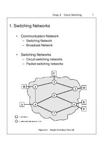
0 1 Fa, N network
Input N-1
Reverse F network a, N
It is easy to see that the Fa,ks t network constructed this way has k s t inputs and ak s t outputs. Furthermore, summing the number of edges in the homogeneous graphs in stage 0 and the extensive graphs in all the remaining stages, the number of edges in the Fa,ks t network is found to be
0 1 Output N-1
Figure 2: A nonblocking network constructed with Fa,N networks.
k s td(at + t)/2e +
s X
δ(k i−1 at)(k s−i+1 )
(2)
i=1
e outputs of its outputs. So, the d (am−m+2) 2 of the first Fa,m network can be connected e outputs of the first to at least d (kam+km) 2 (am, kam, α, β)-extensive graph. Since the number of established paths is at most r, the idle input x can therefore be connected to at least d (kam+km) e − r = d (kam−r+1) + km−(1+r) e 2 2 2 idle outputs. Because 0 ≤ r ≤ km − 1, it follows that x can be connected to at least e idle outputs. Therefore, by Defd (kam−r+1) 2 inition 4, the construction in Figure 1 is an Fa,km network. k Lemma 2 (Bassalygo-Pinsker): Let G be a network obtained by tieing two Fa,N networks back-to-back as shown in Figure 2. G is an N -input strictly nonblocking network. k The 2-stage construction of the Fa,km network in Figure 1 can be applied iteratively to obtain an (s + 1)-stage Fa,ks t network, s = 1, 2, . . . The stage 0 of an Fa,ks t network consists of k s d(at + t)/2e-homogeneous bipartite graphs with t inputs and at outputs. The stage 1 consists of k s (at, kat, α, β)extensive graphs, the stage 2 consists of k s−1 (kat, k 2 at, α, β)-extensive graphs, and, in general, the stage i consists of k s−i+1 (k i−1 at, k i at, α, β)-extensive graphs, where α and β are fixed as in Lemma 1. To complete the design of the Fa,ks t network, Bassalygo and Pinsker showed that there exist bipartite δ-homogeneous (k i−1 at, k i at, α, β)extensive graphs where δ is given by 1−β H(α) + k(1 − α)H( 1−α ) δ =k+d e α log(1/β)
= k s td(at + t)/2e +
s X
(aδtk s )
(3)
i=1
= k s td(at + t)/2e + saδtk s
(4)
aδ aδ (log t)N + N log N log k log k (5) where N = tk s . Even though this result does not lead to an explicit construction of an Fa,ks t network, it can be used to upper bound the number of edges in such a network. In particular, Bassalygo and Pinsker fixed k = 4, a = 50/17, t = 17 α = (a − 1)/2a = 0.33, and β = (a + 1)/2a = 0.67, to obtain a ((50)4i−1 , (50)4i , 0.33, 0.67)-extensive graph for each i, 1 ≤ i ≤ logk (N/17). Each of these is a 23-homogeneous bipartite graph where δ = 23 is worked out from Equation (1). Substituting the values of k, a, and t in Equation (4) and noting that N = (17)4s , the number of edges in the F50/17,N network is determined as d34 ∗ 17 ∗ 4s + 1150s4s e = d67.65N log4 N e. = N d(at+t)/2e−
2.2
Explicit Construction of Extensive Graphs
Bassalygo and Pinsker obtained an N -input nonblocking network with 136N log4 N = 68N log N edges4 by cascading two F50/17,N networks back-to-back, where each F50/17,N network consists of 1 + s = 1 + log4 (N/17) stages, and hence the two networks cascaded together have 2 + 2 log4 (N/17) stages. While this network has O(N log N ) edges and
(1)
and H(·) is the binary entropy function, i.e., H(x) = −x log x−(1−x) log(1−x), 0 < x < 1.
4
The constant factor in the N log N expression was subsequently reduced to 53.4 in [Bas81] by refining the notion of extensive graphs and choosing the values of the parameters more judiciously.
m
m
24
(m,d, c)-expander
A
1 m
m
a min
(m,d, c)-expander
2
m
B m
(m,d, c)-expander
0 k
Figure 3: Explicit construction of an (m, km, α, β)-extensive graph. (The network has m inputs and km outputs.) O(log N ) stages, it is only an existential construction, since the extensive graphs used in its construction were shown only to exist but not explicitly constructed. In order to convert this network to an explicit form, we first obtain an explicit construction of Bassalygo and Pinsker’s extensive graphs by using the following lemma. Lemma 3: Let G = (A, B, E) be a graph obtained by joining together the ith inputs of k (m, d, c)-expanders, 1 ≤ i ≤ m, as shown in Figure 3. G is an (m, km, α, β)-extensive graph, where 0 ≤ α ≤ 1/2 and 0 ≤ β ≤ α(1 + c(1 − α)). Proof: Let X ⊆ A, where |X| = αm ≤ m/2. The inputs in X can be joined to (1 + c(1 − α))|X| outputs of each of the (m, d, c)-expanders and thus can be joined to k(1 + c(1 − α))αm = α(1 + c(1 − α))km outputs of G. This implies that the inputs in X can be joined to βkm outputs of G for all β ≤ α(1 + c(1 − α)). Therefore, G is an (m, km, α, β)-extensive graph with 0 ≤ α ≤ 1/2 and 0 ≤ β ≤ α(1 + c(1 − α)). || The main point of this lemma is that an (m, km, α, β)-extensive graph can be constructed by using k (m, d, c)-expanders. In the context of Lemma 1, this amounts to replacing each of the (k i−1 at, k i at, α, β)-extensive graphs in the ith stage of the Fa,N network, by k (k i−1 at, d, c)-expanders subject to the conditions (i) β ≤ α(1 + c(1 − α)), (from Lemma 3) (ii) α ≤ 1/2 (from Definition 2) (iii) α + β = 1 (from Lemma 1) (1−2α) Combining (i) and (iii) gives c ≥ α(1−α) . Re-
0. 1
c
2
Figure 4: Values of amin with respect to c. calling from Lemma 1 that α = (a − 1)/(2a), (ii) holds for any a > 1. Hence the above three conditions amount to the inequality: (1−2α) c ≥ α(1−α) = a24a−1 , where a > 1. By solving √
this inequality for a, we obtain a ≥ 2+ c4+c . Hence, invoking Lemma 2 to obtain an (m, , a+1 )-extensive graph√ requires that km, a−1 2a 2a √ 2 2 a ≥ 2+ c4+c . We set amin = 2+ c4+c . Now returning to Equation (5), we note that the factor in front of the N log N term is aδ adk given by log or log since the extensive graphs k k used in the Bassalygo-Pinsker network have degree δ = dk. Since N log N is the highest order term in Equation (5), we seek to adk minimize log N log N with respect to a, d k and k, √and subject to the constraint that 2 a ≥ 2+ c4+c . An additional constraint also imposed on a and k is that k i−1 at and k i at, 1 ≤ i ≤ logk (N/t), be both squares since all explicit constructions of (m, d, k)-expanders reported in the literature that we know of have a square number of inputs. This implies that k and at be both squares. Under these conditions, it is obvious that k = 4 adk minimizes log N log N . As for amin , Figure 4 k shows that its values increases as c decreases. While we do not know of a close form relation between d and c, most explicit constructions of (m, d, c)-expanders suggest that d increases with increasing c as seen in Table 1. Among these expanders, Alon et al.’s (m, 9, 0.449)expander with c = 0.412, d = 9 and a = 9.8 adk yields the minimum value for log resulting k adk in log k N log N = 352.8N log N edges. Using two copies of F9.8,N networks and invoking Equation (5) with a = 9.8, d = 9, k = 4 and t = 5 then gives a nonblocking network with 2
Table 1 Various Expanders, their degrees and expansion coefficients
Expander
Degree (d)
coefficient (c)
[Mar73] [GG81] [GG81] [AGM87] [AGM87] [Lee92]
5 5 7 9 13 33
Not known √ (2 − √3)/4 (2 − 3)/2 0.412 0.465 0.868
amin Not known 59.7 29.9 9.8 8.7 4.8
d54N + 705.6N log4 (N/5)e = d−765.18N + 352.8N log N e edges and 2+2 log4 (N/5) = 2+ log(N/5) stages. Table 2 compares the edgecount and number of stages of this network with previously known nonblocking networks5 .
Table 2 Cost and Depth of Various Nonblocking Networks
Network Clos-Cantor [Can71] [Can71] [LP91] [ALM90] [Bas81] This paper
5*4
The Parallel Routing Algorithm
In this section we present parallel algorithms to establish a path between any pair of idle inputs and idle outputs and abolish paths between any number of pairs of busy inputs and outputs in Bassalygo-Pinsker networks. To simplify the description of our algorithms, we will combine the extensive graphs whose outputs are merged together in each stage of the F9.8,N network into a single bipartite graph of degree dk as shown in Figure 5. This simplifies the representation of the F9.8,N network without altering its structure. The single assignment routing problem for a Bassalygo-Pinsker network includes two main tasks: establishing paths and abolishing paths. First, we formalize the pathestablishing problem. Let x be an idle input which requests to be connected to an idle output, say y. A free path between x and y (a path between x and y comprising unused switching vertices) will be established by traversing the left and right Fa,N networks separately. That is, traversals from x to the idle outputs of the left Fa,N network will be combined with the traversals from y to the idle 5
The constant 240, 000 in the edge-complexity of the Multi-Beneˇs network is worked out from an informal remark in the 2nd paragraph of the 2nd column on p.156 in [ALM90].
i-1
Depth
N loga N, 2 < a ≤ 3 O(N log2 N ) O(N log2 N ) 240, 000N log N 53.4N log N +O(N ) 352.8N log N + O(N )
F 9.8,5* 4
i-1
loga N, 2 < a ≤ 3 2 log(N + 2) − 1 2(log N + log log N ) 2(log 300N ) + 1 2 + log(N/17) 2 + log(N/5)
extensive graph 1
extensive graph 2
5*4
3
Cost
i-1
F 9.8,5* 4
i-1
49 * 4 5*4
i-1
F 9.8,5* 4
i-1
extensive graph 3
5*4
i-1
F 9.8,5* 4
i-1
extensive graph 4
Figure 5: Restructured F9.8,5∗4i network. outputs of the right Fa,N network to determine the free paths between x and y. The path-abolishing problem (single routing assignment version) for a Bassalygo-Pinsker network amounts to dismantling an established path between a busy input and its busy output pair. The paths between inputs and outputs must be abolished after the transactions between them are over because leaving the edges on these paths busy invalidates the nonblocking property of a Bassalygo-Pinsker network (any nonblocking network for that matter). That is, unless the paths between the inputs and the outputs that complete their transactions are abolished, the assumption that an input be connected to at most one output at a time does not hold anymore and without this assumption the definition of a nonblocking network no longer applies. We also note that abolishing paths between two or more busy inputs and their busy output pairs is timewise no more complex than abolishing a
i
path between a single busy input and its busy output pair. A. Representation of Paths We will characterize the paths between the inputs and outputs of each Fa,N network in terms of sequences of vertices where each vertex identifies an (output,input) pair (that is, a link between two consecutive stages) of the network. This can be viewed as collapsing the outputs of each stage with the inputs of the succeeding stage without altering their original ordering. We let vertex (i, j) denote the ith vertex between the j − 1th stage and jth stage of the Fa,N network, where i is called the identification (ID) of the vertex, 0 ≤ i ≤ aN and 1 ≤ j ≤ logk (N/t). In particular, (i, 0), 0 ≤ i ≤ aN − 1, denote the input vertices and (i, 1 + logk (N/t), 0 ≤ i ≤ aN − 1, denote the output vertices6 . A vertex in an Fa,N network is said to be occupied if it falls on a path established between a busy input and a busy output; it is called unoccupied otherwise. The status of the vertices in an N -input Fa,N network with parameters a, t, d and k as defined in Lemmas 1 and 3 will be represented by an aN ×(2+logk (N/t)) matrix P such that each entry P [i, j] is a triplet (µi,j , bi,j , Si,j ), 0 ≤ i ≤ aN and 0 ≤ j ≤ 1 + logk (N/t), where7 (i) µi,j is a temporary storage which will be used to store the ID of one of the neighbors of vertex (i, j). Its usage will become clear as we describe the routing algorithm in the following subsection. (ii) bi,j is a binary variable which represents the status of vertex (i, j); vertex (i, j) is occupied if bi,j = 1 and it is unoccupied if bi,j = 0. (iii) Si,j is a dk-element vector where Si,j [r] contains the ID of the rth successor of vertex (i, j), where 1 ≤ r ≤ dk. For an Fa,N network with fixed parameters a, t, d and k, variable Si,j in each entry P [i, j] is fixed for the specific structure of the ex6
This vertex identification scheme will subsequently be simplified for more efficient versions of our algorithms. 7 Note that each Fa,N network has only N vertices in its input stage even though matrix P allocates a column of aN entries for these vertices. This is done to simplify the notation in our discussion.
tensive graph used to build the network, variable bi,j is updated after a request to establish a path or a request to abolish a path has been completed so that they together reflect the current state of the Fa,N network. B. Parallel Path-Establishing Algorithm Given an idle input (Ix , 0) of the left Fa,N network and an idle input (Iy , 0) of the right Fa,N network (equivalently, an idle input-output pair of the entire network containing the left Fa,N network and right Fa,N network), the path-establishing algorithm consists of three phases: path-claiming phase, pivot-selection phase and path-tracing-back phase. Before getting through these three phases, variables µi,j except µIx ,0 and µIy ,0 , in all entries of the status matrices associated with the two Fa,N networks should be initialized with an invalid vertex ID. The invalidation of the µi,j ’s for the intermediate vertices (or links) is necessary in order not to taint the predecessor information that is to be compiled for the current idle input and idle output pair by the predecessor information due to the previously established paths. The µi,j ’s of all other inputs except those for (Ix , 0) and (Iy , 0) are also invalidated to indicate that only inputs (Ix , 0) and (Iy , 0) are to take part in the current round of pathclaiming phase. During the path-claiming phase, we mark all free paths between (Ix , 0) and (Iy , 0) which are vertex-disjoint with the already established paths in the Fa,N networks by linking the vertices along the free paths with the variables µi,j . This phase consists of (2 + logk (N/t)) steps for each Fa,N network (one step for each value of j). During the jth step, each vertex (i, j), 0 ≤ i ≤ aN − 1, with its variable µi,j containing a valid vertex ID in stage j of the Fa,N network broadcasts its ID to its dk successors specified by variable Si,j . Each vertex (i, j + 1), 0 ≤ i ≤ aN − 1, in stage j + 1 keeps only one of its predecessors’ ID’s and stores it in variable µi,j+1 if its variable bi,j+1 = 0 (an unoccupied vertex) and discards all the ID’s from its predecessors if its variable bi,j+1 = 1 (an occupied vertex). Figure 6 illustrates the activities that take place during the jth step, where vertex (i, j) which has received the ID from vertex (p, j−1) in the last step transmits its ID to all its suc-
Stage j-1
Stage j+1
Stage j
(q,j-1)
(l,j+1) (q,j-1)
µ
q,j-1=(q",j-2)
(p,j-1)
(i,j)
(p,j-1)
(i,j) (i,j)
µ p,j-1 =(p",j-2)
(i,j+1)
µ i,j =(p,j-1) (i,j)
(n,j-1)
(m,j+1)
µ n,j-1 =(-1,-1)
Figure 6: Demonstration of the jth iteration of path-claiming phase. cessors, i.e., vertices (l, j + 1), (i, j + 1) and (m, j + 1), which then store in the same step, the ID (i, j) in their variables µl,j+1 , µi,j+1 and µm,j+1 if their corresponding variables bl,j+1 , bi,j+1 , bm,j+1 are equal to 0. We note that vertex (n, j −1) does not transmit its ID to vertex (i, j) as indicated by the dashed line because its variable µn,j−1 does not contain a valid ID. It follows that upon applying the pathclaiming phase to the left Fa,N network, all its idle output vertices that have free paths to the chosen idle input (Ix , 0) can be determined. Likewise, upon applying the same procedure to the right Fa,N network, all its idle output vertices that have free paths to the chosen idle input (Iy , 0) can also be determined. We call each idle output common to both the left and right Fa,N networks a pivot vertex if it can be reached through a path determined by the path-claiming phase from both input (Ix , 0) and input (Iy , 0). That the BassalygoPinsker network is nonblocking ensures that there exists at least one pivot vertex for any given idle input of the left Fa,N network and any given idle input of the right Fa,N network. The pivot-selection phase of the pathestablishing algorithm uses a backward traversal from pivot vertices in the output end of the right Fa,N network toward its input (Iy , 0) to locate a free path. This traversal takes 1 + logk (N/t) steps. More specifically, during step j, 0 ≤ j ≤ logk (N/t), the pivot vertices
in stage 1 + logk (N/t) − j of the right Fa,N network send their ID’s to their neighbors as specified by variables µi,1+logk (N/t)−j . The vertices in stage 1 + logk (N/t) − j − 1 that receive any ID’s from stage 1 + logk (N/t) − j retain only one of these ID’s they receive and then the same step is repeated between the vertices in stage 1 + logk (N/t) − j − 1 and those in stage 1 + logk (N/t) − j − 2 and so on. This phase generates a free path, (linked by variables µi,j ), from the input (Iy , 0) of the right Fa,N network to one of the pivot vertices on its output end. Thus, once the pivot-selection phase is completed, all that remains to be done is to establish a free path by tracing it back from output vertex (Iy , 0) through the pivot vertex in the center to the input vertex (Ix , 0) of the combined network. This path-tracing-back phase takes (2 + logk (N/t) steps on each of the left and right Fa,N networks. We first start from the right Fa,N network and make the idle output (Iy , 0) as the only marked vertex. In the jth step, the marked vertex (i, j) in stage j of the right Fa,N network sets variable bi,j = 1 to indicate that vertex (i, j) is occupied and transfers its ID to its neighbor specified by variable µi,j so that the edge between these vertices in the right Fa,N network is activated. The unique vertex in stage j + 1 which receives this vertex ID becomes the marked vertex in stage j + 1 for the following step. After 2 + logk (N/t) steps, a particular pivot vertex in the center stage will be marked. The same process then proceeds in the left Fa,N network for another 2 + logk (N/t) steps starting with the chosen pivot vertex as marked vertex. At the end of this phase, a free path between (Ix , 0) and (Iy , 0) is established and the request is served. The algorithm to abolish a path is much simpler. Given a busy input (Ix , 0) of the left Fa,N network and a busy input (Iy , 0) of the right Fa,N network, abolishing the path between them only takes one phase which consists of (2 + logk (N/t)) steps on each Fa,N network. Also the busy paths can be abolished in parallel since they are disjoint.
4
Realization mance
and
Perfor-
In this section we will discuss the implementation and performance of the routing algorithm on parallel processors with three different connection topologies. A. Direct Realization In this case, all phases of the routing algorithm associated with the two Fa,N networks presented in the previous section are mapped directly onto a parallel processor with 2N + 2aN × logk (N/t) + aN processors that are interconnected exactly the same way as the vertices are connected in the BassalygoPinsker network. We shall refer to this parallel processor realization as a BP-processor since its topology is patterned after the BassalygoPinsker network. The routing algorithm described in the previous section can be realized on the BPprocessor using either a centralized or a distributed processing scheme. In the centralized scheme, we assume that a master control unit initiates the various phases of the routing algorithm. Recall that the routing algorithm consists of two parts: path-establishing and path-abolishing. In the path-establishing part, upon receiving a request to connect an idle input x to an idle output y, the master control unit activates the processor associated with the idle input and the processor associated with the idle output. Each of these two processors then simultaneously initiates the path-claiming phase. Once the path-claiming phase is completed, those processors in the center stage invoke the pivot-selection phase. After this phase is completed, the processor associated with the idle output y then invokes the path-tracing-back phase. At the end of this phase, a path between idle input x and idle output y is formed. In the distributed scheme, the request for a connection between an idle input and an idle output arrives directly at the processor associated with the idle input and this request must be transmitted to the processor associated with the idle output. This is accomplished by invoking a broadcast of the destination address of the idle output via the processor associated with the idle input to all the processors associated with all the idle outputs. The processor (associated with an idle output) whose destination address matches the broadcast ad-
dress is then activated to initiate the three phases of the path-establishing process. These three phases are also carried out by the processor associated with the idle input. The rest of the realization proceeds as in the centralized scheme. It follows that all three phases of the path-establishing algorithm can be completed in 4 ∗ (2 + logk (N/t)) = O(log N ) steps on the BP-processor under the centralized scheme and in 6 ∗ (2 + logk (N/t)) = O(log N ) steps under the distributed scheme. Similarly, it can be shown that the path-abolishing algorithm can also be realized on the same parallel processor in (2 + logk (N/t)) = O(log N ) steps under the centralized scheme and 3 ∗ (2 + logk (N/t)) = O(log N ) steps under the distributed scheme. B. Indirect Realizations It should be obvious that the parallel processor realization just described can be simplified by combining some of the processors together and restructuring the communication links between them so as to maintain the connectivities in the original topology of the BPprocessor. In general, this can lead to a variety of realizations with centralized routing schemes for the Bassalygo-Pinsker network. One possibility is to collapse all the processors into a single column of aN processors and restructuring the communication links so that if any two processors have a direct communication link before the contraction, they have a direct communication link after the contraction as well. Since each vertex in a stage of the BP-processor is connected to dk successors in the succeeding stage. Therefore, each processor in the contracted BP-processor would have dk(2 + logk (N/t)) communication links connecting it to the other processors. Thus, the contracted BP-processor consists of O(N ) processors and a total of O(N log N ) communication links. We leave out the details of the realization of the path-establishing algorithm on this contracted BP-processor and only mention that it can be realized in 5 ∗ ((2 + logk (N/t))) = O(log N ) steps. The path-abolishing algorithm can similarly be realized on the same processor with a time complexity of 2 ∗ ((2 + logk (N/t))) = O(log N ) steps. The same algorithm can be realized on other parallel computers consisting of O(N ) processors. In particular, we can realize this routing
algorithm on a perfect shuffle processor using the data broadcast algorithm of Nassimi and Sahni [NS81]. Consider a perfect shuffle processor with aN processors, and suppose that processor P (i) contains an index register W (i) and data register D(i). Nassimi and Sahni described an algorithm, called random access write (RAW) that broadcasts the contents of D(i) in processor P (i) to processor P (W (i)), 0 ≤ i ≤ aN − 1. If two or more processors attempt to broadcast to the same processor, that is, If W (i1 ) = W (i2 ) = ... = W (ir ) = i, then P (i) receives its data from P (j), where j = M in1≤k≤r {ik }. This algorithm takes O(log2 N ) steps to execute on a perfect shuffle processor. The various phases of the routing algorithm described in Section 3 can be broken down into a sequence of steps each of which amounts to executing the Nassimi and Sahni’s data broadcast algorithm. To see this, consider the path-claiming phase of the parallel path-establishing algorithm. In the BP-processor realization, each processor within a stage broadcasts its own ID to its dk successors in the next stage. On the receiving end, each processor keeps only one of the ID’s that reach it. This broadcasting of ID’s between the processors in consecutive stages can be performed by iterating the Nassimi and Sahni’s RAW algorithm dk times, where, during each iteration, all active processors send their ID’s to one of their successors. Since each iteration takes O(log2 N ) steps and a total of dk iterations are needed to complete the broadcast of the ID’s for all active processors during each step of path-claiming algorithm and since the entire algorithm encompasses O(log N ) steps, the path-claiming phase can be completed in O(log3 N ) steps on a perfect shuffle processor with O(N ) processors using Nassimi and Sahni’s algorithm. It should be noted that this realization increases the time complexity from O(log N ) to O(log3 N ) when compared to the fully-contracted BPprocessor, but it only requires O(N ) communication links as compared to O(N log N ) communication links for the fully-contracted BP-processor.
Table 3 Processor, time and link complexities of various parallel processor realizations of the routing algorithm
Realization
No. of processors
BP-processor Contracted BP-processor Perfect shuffle processor
O(N log N ) O(log N ) O(N ) O(log N )
5
O(N )
Execution time
O(log3 N )
No. of links O(N log N ) O(N log N ) O(N )
Concluding Remarks
Table 3 summarizes the processor and time complexities of the various realizations of our routing algorithm. The steps in both direct and indirect realizations involve broadcasting, updating vertex ID’s and checking binary variables. In section 3A, we stated that a switching vertex in a Bassalygo-Pinsker network will be given or assigned a pair (i, j) as its ID (see footnote 6). For an N input Bassalygo-Pinsker network this implies that the ID of each vertex takes up O(log N ) bits, and hence broadcasting and updating ID’s would require O(log N ) bit-steps. Fortunately, the bit-level complexity of the steps in our algorithms can be reduced to O(1) by noting that each vertex in Bassalygo-Pinsker network has only 2dk neighbors and thus it suffices to use 2 log(dk) = O(1) bits to identify the neighbors of a vertex. Therefore, broadcasting a vertex ID reduces to setting a single-bit flag and identifying the neighbor that sets a single-bit flag reduces to encoding a log(dk)-bit address which can be done in O(log2 (dk)) = O(1) bit-steps. Recalling that the three phases of the path-establishing algorithm requires 4 ∗ (2 + log4 (N/5) steps, the total bit-level time complexity of this algorithm will be ≈ 4 ∗ dlog(dk)e2 ∗ (2 + log4 (N/t) = 72 log N +120.82 when d = 9, k = 4 and t = 5. While these results are rewarding, it will be worthwhile to further reduce the constant 352.8 in the crosspoint expression of the nonblocking network described in the paper. This would require new constructions of expanders with lower densities and larger expansion coefficients. Another direction for further research is to extend the path selection algo-
rithm of this paper to handle multiple connection requests. Such requests can be handled by iteratively applying the algorithm given in this paper, but this is likely to lead to excessive routing time when the number of requests gets very large. These problems and other related questions will be dealt with in detail elsewhere.
References [ALM90] S. Arora, T. Leighton, and B. Maggs. On-line algorithms for path-selection in a nonblocking network. In Proc. ACM Sym. on the Theory of Comp., pages 149–158, 1990. [Bas81] L. Bassalygo. Asymptotically optimal switching circuits. Problems of Info. Trans., 17:206–211, July-September 1981. [Ben65] V. Bene˘s. Mathematical Theory of Connecting Networks and Telephone Traffic. Academic Press Pub., New York, 1965. [BP74] L. Bassalygo and M. Pinsker. Complexity of optimum nonblocking switching without reconnections. Problems of Info. Trans., 9:64–66, January-March 1974. [Can71] D. G. Cantor. On non-blocking switching networks. Networks, 1:366–377, 1971. [Clo53] C. Clos. A study of nonblocking switching networks. Bell Systems Technical Journal, 32:406–425, February 1953. [GG81] O. Gabber and Z. Galil. Explicit constructions of linear sized superconcentrators. Jour. of Comp. and Sys. Sci., 22:407– 420, 1981. [Lee92] C.Y. Lee. Networks for fast efficient unicast and multicast communications. Ph. D. Dissertation, University of Maryland, May 1992. [LP91] G. Lin and N. Pippenger. Parallel algorithms for routing in nonblocking networks. In Proc. ACM Sym. on the Theory of Comp., pages 272–277, 1991.
[Mar73] G. A. Margulis. Explicit construction of concentrators. Problem of Info. Trans., 9:325–332, 1973. [NS81] D. Nassimi and S. Sahni. Data broadcasting in SIMD computers. IEEE Trans on Comp., C-30:101–107, February 1981. [AGM87] N. Alon, Z. Galil, and V.D. Milman. Better expanders and superconcentrators. Jour. of Algorithms, 8:337–347, 1987.