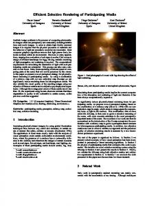
Feb 7, 2003 - needs too much memory. Using a normal texture of. 128x128 pixel for each of the approx. 8,000 patches of our Volkswagen Golf model would ...
Efficient NURBS Rendering using View-Dependent LOD and Normal Maps Michael Guthe
Reinhard Klein
University of Bonn Institute of Computer Science II Römerstraße 164 D-53177 Bonn, Germany
{guthe,rk}@cs.uni-bonn.de ABSTRACT Rendering large trimmed NURBS models with high quality at interactive frame rates is of great interest for industry, since nearly all their models are designed on the basis of this surface type. Most existing approaches transform the NURBS surfaces into polygonal representation and build static levels of detail. Unfortunately, algorithms which keep the NURBS representation and generate view-dependent LOD on the fly suffer from the problem, that they only calculate the geometric error of an approximation, but no care is taken of the illumination artefacts introduced by the chosen view-dependent triangulation. Normal maps have proven to be very accurate in providing better visual quality without increasing the complexity of the geometry itself and thus solving this problem, but need much memory to store the normal textures. In this paper we present a novel approach to apply normal maps to view-depandent NURBS rendering with small memory and computational overhead. Additionally, we apply our approach to render isophotes and environment maps such as reflection lines on view dependent triangulations with high visual fidelity.
Keywords NURBS rendering, appearance-preserving LOD, normal maps, environment mapping, reflection lines
1. INTRODUCTION The industrial design of models for prototyping an production is nearly always performed with the support of Computer Aided Design (CAD) geometric modeling tools. The fundamental geometric entities in such systems are trimmed Non-Uniform Rational B-Splines (NURBS) due to their ability to conveniently describe surfaces of almost any shape. Since current graphics hardware does not support direct rendering of trimmed NURBS in their original representation, they need to be transformed e.g. into a polygonal representation (tessellation). Rendering these tessellations at high frame rates with high quality is an important problem, as many models from industry are very complex (thousands of Permission to make digital or hard copies of all or part of this work for personal or classroom use is granted without fee provided that copies are not made or distributed for profit or commercial advantage and that copies bear this notice and the full citation on the first page. To copy otherwise, or republish, to post on servers or to redistribute to lists, requires prior specific permission and/or a fee. Journal of WSCG, Vol.11, No.1., ISSN 1213-6972 WSCG’2003, February 3-7, 2003, Plzen, Czech Republic. Copyright UNION Agency – Science Press
patches) and thus require millions of triangles for an accurate visualization. Reducing the number of triangles to be rendered can be achieved by two main techniques: •
Culling techniques like view frustum, backface and occlusion culling reduce the number of triangles by deciding which are not visible.
•
Level of detail (LOD) techniques try to minimize the number of triangles before sending them to the graphics pipeline.
Traditional NURBS rendering approaches which support LOD generate a very fine triangulation at the beginning which is stored along with a hierachy of static LODs or a progressive representation. A more renecent approach which generates the desired LOD on the fly from the NURBS surface itself does not take care of visual artefacts introduced by the triangulation. The main problem is, that the only error measure that can be used for realtime applications to select the necessary LOD is an upper bound of the geometric error. As the model is rendered, the shading model is only evaulated at the vertices of the current triangulation, leading to visual
artefacts, especially at highlights and when rendering isophotes or reflection lines.
1.1 Main Contributions In this paper we introduce a new method for rendering complex trimmed NURBS surfaces with high quality at interactive frames rates, by extending a previous view-dependent LOD technique for trimmed NURBS surfaces [GMK02] by the use of normal maps. The main advantages of our approach are: •
Using a special parametrization for the normal map, the memory and computational overhead are very small compared to previous appraches.
•
Software shading and hardware shading with NVidia Register Combiners or ATI Fragment Shaders to render the LODs with normal mapping can be used.
•
The algorithm supports the rendering of environment maps, isophotes and reflection lines in combination with view-dependent LOD with high visual fidelity.
1.2 Paper Structure The rest of the paper is organized as follows: In section 2 results from related areas are discussed. In section 3 we briefly describe the overall rendering algorithms our extension is build on. Section 4 covers the description of our new algorithm and its integration into the existing framework. In section 5 we report results and section 6 concludes and describes future work.
2. RELATED WORK 2.1 Level of Detail Creating levels of detail (LOD) for geometric objects has become a common approach in the last decade, a good overview of LOD techniques can be found in [Lue01]. One of the early results by Hoppe [Hop96] introduced progressive meshes and edge collapses. This approach was improved to yield viewdependent, progressive LODs by Xia et al. [XV96], Hoppe [Hop97] and Klein [KK97][Kle98], while Luebke et al. [LE97] introduced view-dependent LOD for arbitrary topology. The vertex numbering scheme introduced by El-Sana and Varshney [EV99] encodes partial ordering of the simplifications steps very efficiently. A recent publication proving the efficiency of the view-dependent approach is [Paj01]. The main drawback of these view-dependent LOD techniques is the huge amount of memory needed to store the hierarchy, see [FMP02].
2.2 Trimmed NURBS Rendering Rendering trimmed NURBS surfaces has been a field of great interest in the recent years. Different approaches have been elaborated for visualization, like ray-tracing [NSK90], pixel level subdivision [SC88] or polygon tessellation [HB87][RHD89] [FK90][KS95], of which the triangle based methods are generally much faster especially due to recent advances in graphics hardware. On a multiprocessor system these triangulated models can be rendered at interactive rates [BSGM02], but this requires massive amounts of memory for storing the hierarchical static levels of detail, since every vertex of the finest triangulation needs approximately 65 Bytes of memory (including vertex normals) [FMP02]. However, current approaches are able to render trimmed NURBS at interactive frame rates by combining several patches to so-called supersurfaces. The approach made by Kumar et al. [KMZH97] statically clusters sets of trimmed NURBS patches that need to be sewn at runtime. A more recent approach [GMK02] based on a technique to repair CAD models [KBK02] provides a more accurate visualization at higher frame rates by using a non-manifold data structure to store the sewn trimming curves between patches that are somputed in a preprocessing step and generate triangulations on the fly. The problem is that all the above approaches only control the geometric error of the tessellation leading to visible popping artefacts in the shading, when the LOD of a patch changes. Furthermore, highlights of distant surfaces are not rendered correctly. This cannot be solved by Phong shading only, since the surface normal does not change linearly over the patch and thus information is missing. In priciple this problem can be solved by choosing the adaptive LOD based on a geometric and illumination based criterion [KS99] but only at the cost of a higher polygon number.
2.3 Normal Maps The missing normal information of simplified meshes needed for correct shading can be stored easily in normal maps [COM98], which can be shaded efficiently in software or on programmable graphics hardware [TCRS00]. Recently Cole applied normal maps to view-dependent level of detail [Col01] and showed their efficiency. Using normal maps dramatically reduces popping artefacts due to incorrect shading, but generating a normal map texture with fixed size for every patch like [COM98] needs too much memory. Using a normal texture of 128x128 pixel for each of the approx. 8,000 patches of our Volkswagen Golf model would require
375MB of texture memory.
4.
2.4 Parametrizations A few approaches to compress textures on polygonal models without loss of quality have been proposed in the recent years. Sloan et al. [SWB98] generate an importance map for a given 2D parametrization and warp this square texture to evenly distribute this scalar field. Another approach approximating a 2D image [TV91] uses a dynamic simulation, where grid edge weights are set according to local image content. This method was extended to 3D surfaces Balmelli et al. [BTB02] and by Sander et al. [SGSH02] using a pre integrated signal stretch metric. They have proven to dramatically reduce texture size compared to a non specialized parametrization without loss of quality. All methods in this field have in common that they generate a piecewise linear parametrization on a surface. This parametrization can be stored efficiently for polygonal meshes as texture coordinates of the vertices. But storing this information in addition to the existing NURBS parametrization again results in a high memory overhead.
generation of a multiresolution representation of these sewn poly-lines resulting in the hierarchical Seam Graph
Note, that the sewing is not necessary if the adjacency relations between boundary curves are provided by the CAD-System. The conversion of the trimming curves and the sewing are the most time consuming parts of the preprocessing, but the generated data can be stored efficiently on disc. The interactive rendering stage consists of four phases: 1.
computation of the acceptable, view-dependent geometric error per patch
2.
selection of the view dependent LOD in the Seam Graph
3.
culling of invisible patches
4.
adaptive, view-dependent tessellation of those visible NURBS surfaces which require updates
3.1 Seam Graph
In the following we briefly describe the NURBS renderer framework. The overall algorithm to render a soup of trimmed NURBS patches can be divided into a preprocessing stage and an interactive rendering stage. The main data structure of this algorithm is the Seam Graph. It consists of all trimming curves of the NURBS patches that were sewn together in the preprocessing step (see figure 1).
The trimming curves are first approximated with a given geometric error in 3D space and then sewn together into a non-manifold graph. The Seam Graph data structure [GMK02] was designed to handle a multi resolution representation of non-manifold surfaces. The idea is to store a non-manifold surface as set of manifold surfaces (patches) which are sewn at non-manifold boundary edges. The vertices of the edges represent the sewing points in Euclidean space. Each vertex holds a pointer to each adjacent patch. Then a multi resolution representation of the edges is generated using standard edge collapse operations. If all boundary vertices of a patch are collapsed during simplification the patch itself also disappears. In this case the inner of the patch must not be triangulated further.
Figure 1. Example of a Seam Graph
The cost function used for simplification of the Seam Graph is the one-sided Hausdorff distance described in [KLS96]. Since this error measure has a high computational complexity, the cost computation is split into two parts by first calculating an upper bound for the error and only computing the one-sided Hausdorff distance, when an edge is chosen for collapse. The upper bound for the error is the sum of distances of the actual edge and its 1-ring to the original edges and to the simplified edges.
3. NURBS RENDERER FRAMEWORK
This preprocessing stage consists of four phases: 1.
reading a set of trimmed NURBS patches without neighbourhood information
2.
conversion of trimming curves into poly-lines guaranteeing an upper approximation error bound
3.
sewing of adjacent poly-lines with an error in order of magnitude of the modeling tolerance
3.2 Rendering 3.2.1
Culling
Since the algorithm keeps separate patches, standard culling techniques [MH99] can easily be applied on the patches, thus reducing the number of patches that
have to be triangulation and the number of rendered triangles.
3.2.2
2
LOD Selection
Before selecting the view-dependent LOD for the Seam Graph, an upper bound ε of the geometric error is calculated for every patch. A single LOD is chosen for the whole patch, since a view dependent triangulation of a patch would require the traversal of the approximation-tree of every patch for every frame. Furthermore, since the patches are relatively small the perspective transformation can be neglected. Nevertheless, for each patch a individual LOD is chosen. The LOD selection of the Seam Graph now uses these patch errors to select the view-dependent LOD by choosing the lowest error of all visible adjacent patches as error for every vertex. If a vertex has no visible adjacent patches it is not visible itself and thus skipped.
3.2.3
This behaviour is resembled by the following discrete energy:
On the fly Triangulation of the patches
After selecting the appropriate view dependent LOD of the Seam Graph the inner of the individual patches is triangulated on the fly. To reduce the number of generated triangles without increasing the computation cost, a kd-tree is used to store the geometric error of the current subdivision of a patch as well as the parameter line where the next subdivision is applied. To find this line, first the point on the surface with maximum distance to the current subdivision is computed and then the tree cell is sundivided along a u or v parameter line through this point. In such a way must faster convergence is achieved than using a simple quad-tree for subdivision. After subdividing the parameter space the trimming is performed by the edges of the Seam Graph and the resulting trimmed kd-tree patches are triangulated. Finally, the parameter vertices are mapped to 3D space directly using the NURBS surface.
E=
b JG JG JG where S ( a,b ) = ∫ n′′ ds ≈ arccos n′ ( a ) ⋅ n′ ( b ) ,
(
which is similar to the edge length distortion energy [DMA02]. This similarity is due to the fact that S(a,b) can be interpreted as the arclength between two normals on the the unit sphere. To compute this reparametrization, we use a regular grid in the parameter space of the patch as base geometry. To minimize the energy we minimize the local energy of every vertex with respect to each vertex of its 1-ring [DMA02], until a given threshold is reached. During this minimization the border of the parametrization is fixed on a rectangle. To provide a good starting parametrization we first calculate the maximum signal over the patch in uand v-direction (Sumax and Svmax, respectively) to determine the size of the normal texture. Afterwards, we compute a simple 1D signal stretch parametrization Pu and Pv along u and v, respectively. Sui ,0 = 0
Sv0 , j = 0
Sui , j = S( ai , j ,ai , j −1 )
Svi , j = S( ai , j ,ai −1, j )
n
Sv j = ∑ Svi , j
Sumax = max ( Sui )
Svmax = max ( Sv j )
j =1
∂n ′ ∂u ∂n ′ ∂v
i =1
i =1...m
Pui , j
Su = max Sui
j =1...n
j
∑ Su k =1
Pvi , j
i ,k
Sv = max Sv j
i
∑ Sv k =1
k,j
Where i and j denote the indices of grid points on parameter domain. These 1D parametrizations Pu and Pv are combined to Pi,j = (Pui,j Pvi,j) (see figure 2) and the minimization is started.
P
Pu
Pv
qu ( u ,v )× qv ( u ,v )
n = n′ D t
such that and
qu ( u ,v )× qv ( u ,v )
m
Sui = ∑ Sui , j
In addition to the intrinsic parametrization of the NURBS patches, we apply a specialized reparametrization t : Ω → Ω′ of the normal texture
( u,v ) →
)
a
4. NORMAL MAPS 4.1 Parametrization
n : Ω → S2 ,
( ( ui′ ,vi′ ) − ( u ′j ,v′j ))2 2 − 1 , ∑ ′ ,vi′ ) ,( u ′j ,v ′j ) ) ) S u ( ( ( i i , j∈Edges
= ∇n ′ ≈ 1 ,
that is unit changes of the normals correspond to unit distances of the parameter values in Ω′ .
Figure 2. Generating start parametrization
4.2 Approx. by NURBS parametrization The problem with this piecewise linear signal stretch parametrization is that we have to store it on a per vertex basis, which results in additional storage cost. To overcome this problem we approximate the
piecewise linear parametrization by a higher order NURBS parametrization [PT97] over the same knotvector as the surface patch itself. In this way we have two NURBS patches q and t on the same parameter domain. q:Ω→\
3
q ( u,v ) = ∑ i =u0 ∑ j =v 0 Bi ,ku ( u ) B j ,kv ( v ) Qi , j m
m
t : Ω → \2 t ( u,v ) = ∑ i = 0 ∑ j = 0 Bi ,ku ( u ) B j ,kv ( v ) Ti , j mu
mv
This is reasonable, as the changes of the normals in general are smooth on most NURBS models. The advantage of this approximation is, that it reduces the storage costs and furthermore, the evaulation of the texture coordinates can be done using the same basis functions for both the geometric data and the texture data. Instead of 3D geometry vectors, 5D geometry and texture vectors used. To find this NURBS approximation of the signal stretch parametrization we use a standard approximation algorithm for NURBS surfaces described in [PT97]. The parametrization of each NURBS patch without using adjacency may lead to filtering artefacts due to discontinuities in shading and material. Since we use the Seam Graph structure and thus preserve the boundaries of the NURBS patches up to a visible error of half a pixel, these artefacts are greatly reduced compared to standard simplification techniques. Nevertheless, better filtering is subject of further research.
4.3 Shading We implemented two different shading algorithms. The first calculates the shading in software by setting up a lookup table of the 8192 discrete normals for every material using the Phong lighting model and then generating a light map texture by performing a lookup for every pixel of the normal map texture. The second performs the shading in hardware with NVidia’s Register Combiners or ATI’s Fragment Shaders. Figure 3 shows the setup for Phong shading with different exponents. The dashed lines at the input registers denote whether the alpha value is used or not. Note that the diffuse and specular color values need to be multiplied with the lightsource color before rendering. When using software shading, the renderer is limited to 8192 different normals, because of the high computation cost of the phong rendering equation. When using hardware shading, more normals are possible, but the phong exponent has a limited set of values (eg. 2, 4, 8, and 16 when using a GeForce3 and single pass rendering). Furthermore, software
general combiner 0
input registers direction of light normal map halfway vector diffuse color specular color
const color 0
-
A
A A B
texture 0
A
C D
D
primary color second color
C
C
-
A
D
CD
RGB Alpha
general combiner 2, …, n
final combiner E
AB B
AB B
B
const color 1
RGB
general combiner 1
A EF
F
C
B ZERO
C
AB + (1-A)C + D
D
D
fragment RGB
A
Figure 3. Register Combiner setup shading allows the use of any shading equation like Lambertian or BRDFs.
4.4 Load Balancing As in [GMK02] load balancing between consecutive frames is achieved by restricting the number of updated and triangulated patches per frame to guarantee constant frame rates. During triangulation a vertex split or edge collapse is only allowed if this operation does not exceed the allowed number of updated triangles per frame. Every triangulation has a valid range between the maximum error of the current binary-tree leafs ( ε min) and the minimum error of their parents ( ε max). Thus a patch only needs to be triangulated if its desired error ε lies outside this range. These are recursively selected for triangulation by a weight function w: ( ε min / ε )2 , ε < ε min ε ≥ ε max w = ε / ε max , 0 , else
When normal maps are used the angle α with minimum |cos α | is computed during back-face culling using the normal cone of the patch. Since sin α is the relation between the geometric and the visible error, the weight function changes to:
(
)
max 1,( ε ⋅ sinα / ε )2 , ε < ε min min ε ≥ ε max w = ε / ε max , 0 , else
As in [GMK02] we extent the weight function to update culled patches only if calculation time is left to: patch visible w, w′ = − 1 1 patch culled / w,
Triangulation is stopped if all patches have a weight of zero, or the new patch would increase the number of tessellated triangles above a given threshold. The update is restricted to at most 1,000 new and 10,000 updated parameter space triangles per frame. If the visible error ε vis exceeds 1 pixel unit, the number of new triangles is modified to be 1,000 · ε vis reducing the error at the cost of lower frame rates. The visible error is calculated by following function: OpenGL lighting max ( ε min / ε ) all patches (ε min ⋅ sinα / ε ) normal maps allmax patches
ε vis =
This reduces the visible error when using normal maps and thus increases the frame rate. Additionally we extend the load balancing to the Seam Graph for large models. Since the desired error of Seam Graph vertices is temporally coherent, the active vertices can be split into three groups: 1.
vertices that need to be split
2.
vertices that can be collapsed
3.
vertices with correct error
The vertices in group 1 and 2 are checked every frame to prevent unnecessary splits and collapses, but only 1,000 of the vertices in the third group are checked per frame.
4.5 Env. mapping & Reflection lines Environment mapping is only implemented in software so far and is a simple alteration of the shading lookup table. For each material the environment map is prefiltered with the according Phong exponent and an environment map for diffuse lighting is calculated. Instead of evaluating a shading model, the reflected ray depending on the normal and the viewing direction is calculated and two texture lookups are conducted: one in the diffuse texture with the normal and one in the specular texture of the material with the reflected ray.
5. RESULTS The quality of the approximation is calculated as the sum of square distances weighted with the local area of the samples [SGSH02], where the deviation of the normal signal between the signal stretch compressed normal map is calculated in degree. Since we use 8192 normals for software shading, leading to a resolution of 2.8125°, we choose multiples of this resolution for the signal stretch resolution in our normal map texture. Table 1 shows the signal approximation error, with hardware shading (left) and software shading (right), for different sampling resolutions using the grid directly
and its NURBS Texture Surface [GVW00] approximation using the same knot vectors. The grid resolution used is 16x16 cells. wheel rims car body comp. car 1 1 9 302 1,620 8,036 signal stretch resolution: 5.625° 97x1024 195x1024 1282x1024 texture size 2.73°/2.93° 2.07°/2.24° 2.15°/2.36° SAE grid 2.87°/2.93° 2.07°/2.30° 2.15°/2.36° SAE Nurbs signal stretch resolution: 11.25° 37x1024 101x1024 643x1024 texture size 4.77°/4.97° 2.76°/2.89° 3.33°/3.46° SAE grid 4.85°/4.89° 2.75°/2.89° 3.33°/3.49° SAE Nurbs materials patches
Table 1. Results of NURBS normal maps at different resolutions The best relation between signal approximation error (SAE) and texture size is at a signal stretch resolution of 11.25°. Note that the NURBS approximation even leads to a lower SAE than the grid in some cases. Storing the signal stretch grid needs 2312 Bytes per surface (17.7MB for the complete car), while the NURBS needs only approx. 200 Bytes per surface (1.5MB for the complete car). The minimization of the signal stretch grid takes 39.4 iterations on average per surface for the Volkswagen Golf model with a threshold of 0.1 pixel and a resolution of 11.25° per pixel using our start parametrization. Note that using a uniform grid as start parametrization leads to 56.6 iterations per surface. The preprocessing times and rendering statistics for the complete car model are shown in table 2. preprocessing max. triangles avg. fps max. error memory
OpenGL 436 sec 46,896 13.420 2.716 103.1MB
normal maps 1348 sec 48,556 10.181 3.098 107.1MB
Table 2. Results different shading algorithms The software shader can render approx. 1,000 materials per second. Furthermore, some extra time is needed to compute texture coordinates. The additional memory allocation is 200 Bytes per surface for signal stretch parametrization and 3KByte per line of normal map textures (2556KB) and 2KByte per line used (1286KB) for normal indices. Figure 4 shows the visible geometric error and the frame rates of the three algorithms while rendering the animation. When using hardware normal map shading the only computational overhead is caused by computing the texture coordinates. Furthermore, the memory allocation is reduced compared to software shading,
Finally figure 7 shows a wheel rim rendered with isophotes and a reflection lines environment texture.
(a) results using OpenGL shading
(b) results using hardware normal map shading Figure 4. Visible error and frame rates of different algorithms because only normal map textures are needed, which require 3KByte per line (2556KB). The difference in the visible error is low, since it is a geometric and not shading dependent error. Figure 5 and 6 show a frame from the rendered animation using OpenGL shading and with normal map shading.
Figure 5. Image from animantion using OpenGL shading
Figure 7. Wheel rim rendered with isophotes and reflection lines The videos of the rendered animation are presented at http://cg.cs.uni-bonn.de/project-pages/opensgplus/videos/.
6. CONCLUSION & FUTURE WORK In this paper we presented a novel method to efficiently add normal maps to NURBS models by employing a signal stretch technique for the normals and modifying it to produce texture control points. We showed that our method works very well as extension to an existing NURBS visualization system and improves the visual quality without significantly reducing the frame rate. As an addition to normal map shading in software and hardware, we implemented environment mapping into our shader giving designers important feedback with reflection line environment maps. As future work we will implement the environment mapping in the hardware shader and explore different approaches to prevent filtering artefacts of the material textures and normal maps caused by the LOD algorithm.
7. ACKNOWLEDGMENTS This project was partially funded by the German Ministry of Education and Research under the project of OpenSG Plus. We thank Volkswagen and DaimlerChrysler for providing us with the trimmed NURBS models. Figure 6. Image from animation using normal maps Note that both images were rendered at a resolution of 1024x768 and have a visible geometric error of 0.67 pixel. When using OpenGL shading, the appearance of the patches is not considered leading to visible artefacts (see magnified region in figure 5). The normal map shading is appearance-preserving and thus renders visually correct shading (see magnified region in figure 6).
8. REFERENCES [BSGM02] W. V. Baxter, A. Sud, N. K. Govindaraju, and D. Manocha, Gigawalk: Interactive walkthrough of complex environments, 2002. [BTB02] L. Balmelli, G. Taubin, and F. Bernadini, Space-Optimized Texture Maps. Computer Graphics Forum 21(3), pp.411-420, 2002. [Col01] F. Cole, View Dependent Appearance Preserving Simplification. Computer Graphics Special Topics, 2001.
[COM98] J. Cohen, M. Olano, and D. Manocha, Appearance-Preserving Simplification. Proceedings of SIGGRAPH ’98, in Computer Graphics, Annual Conference Series, 1998. [DMA02] M. Desbrun, M. Meyer, and P. Alliez, Intrinsic Parametrizations of Surface Meshes. Computer Graphics Forum 21(2), 2002. [EV99] J. El-Sana and A. Varshney, Generalized view-dependant simplification. Computer Graphics Forum 18(3), pp.83-94, 1999. [FK90] D. R. Forsey and R. V. Klassen, An adaptive subdivision algorithm for crack prevention in the display of parametric surfaces. In Graphics Interfaces ’90, pp.1-8, 1990. [FMP02] L. D. Floriani, P. Magillo, and D. S. E. Puppo, A multi-resolution topological representation for non-manifold meshes. in 7th ACM Symposium on Solid Modeling and Applications, 2002. [GMK02] M. Guthe, J. Meseth, and R. Klein, Fast and memory efficient view-dependant trimmed NURBS rendering. In Pacific Graphics 2002, 2002. [GVW00] H. Grahn, T. Volk, and H. J. Wolters, NURBS in VRML. In Proceedings of the Web3D-VRML 2000 fifth symposium on Virtual reality modeling language, pp.35-43, 2000. [HB87] B. von Herzen and A. H. Barr, Accurate Triangulations of Deformed Intersecting Surfaces. In ACM SIGGRAPH, pp.103-110, 1987. [Hop96] H. Hoppe, Progressive meshes. Computer Graphics 30, pp.99-108, 1996. [Hop97] H. Hoppe, View-dependent refinement of progressive meshes. Computer Graphics 31, pp.189-198, 1997. [KBK02] F. Kahlesz, A. Balazs, and R. Klein, Multiresolution rendering by sewing trimmed NURBS surfaces. in 7th ACM Symposium on Solid Modeling and Applications 2002, pp.281288, 2002. [KK97] R. Klein and J. Krämer, Multiresolution representations for surface meshes. In Proceedings of the SCCG, pp.57-66, 1997. [Kle98] R. Klein, Multiresolution representations for surface meshes based on the vertex decimation method. Computers and Graphics, 22(1), pp.1326, 1998. [KLS96] R. Klein, G. Liebich, and W. Straßer, Mesh reduction with error control. In IEEE Visualization ’96, pp.311-318, 1996.
[KMZH97] S. Kumar, D. Manocha, H. Zhang, and K. E. Hoff, Accelerated walkthrough of large spline models. in 1997 Symposium on Interactive 3D Graphics, pp.91-102, 1997. [KS99] R. Klein, A. Schilling, Efficient rendering of multiresolution meshes with guaranteed image quality. in The Visual Computer 99, 1999. [LE97] D. Luebke and C. Erikson, View-dependent simplification of arbitrary polygonal environments. Computer Graphics 31, pp.199208, 1997. [Lue01] D. Luebke, A developer’s survey of polygon simplification algorithms. In IEEE CG & A, pp.24-35, 2001. [MH99] T. A. Moeller and E. Haines, Real Time Rendering. A K Peters Ltd., 1st edition, 1999. [NSK90] T. Nishita, T. W. Sederberg, and M. Kakimoto, Ray tracing trimmed rational surface patches. in Computer Graphics 24, pp.337-345, 1990. [PT97] L. Piegl and W. Tiller, The NURBS Book, Second Edition. Springer, 1997. [RHD89] A. Rockwood, K. Heaton, and T. Davis, Real-Time Rendering of Trimmed Surfaces. In ACM SIGGRAPH Proceedings 23(3), pp.149156, 1989. [SC88] M. Shanz and S.-L. Chang, Rendering trimmed NURBS with adaptive forward differencing. In Computer Graphics 22, pp.189198, August 1988. [SGSH02] P. V. Sander, S. J. Gortler, J. Snyder, and H. Hoppe, Signal-Specialized Parametrization, 13th Eurographics Workshop on Rendering, 2002. [SWB98] P.-P. Sloan, D. Weinstein, and J. Brederson, Importance driven texture coordinate optimization. Computer Graphics Forum 17(3), pp.97-104, 1998. [TCRS00] M. Tarini, P. Cignoni, C. Rocchini, and R. Scopigno, Real Time, Accurate, Multi-Featured Rendering of Bump Mapped Surfaces. Computer Graphics Forum 19, 2000. [TV91] D. Terzopoulos and M. Vasilescu, Sampling and reconstruction with adaptive meshes. CVPR 1991, pp.70-75, 1991. [XV96] J. C. Xia and A. Varshney, Dynamic viewdependent simplification for polygonal models. In IEEE Visualization ’96, pp.335-344, 1996.