The support for hardware occlusion queries (HOQ) [7] ... With hardware occlusion queries, the GPU ..... [7] M. Craighead, âGL NV occlusion queryâ, OpenGL.
Efficient Real-Time Rendering of Building Information Models M. Johansson and M. Roupé Department of Civil and Environmental Engineering Chalmers University of Technology, Göteborg, Sweden Abstract - A Building Information Model (BIM) is a powerful concept, since it allows both 2D-drawings and 3D-models of buildings or facilities to be extracted from the same source of data. Compared to a general 3D-CAD model a BIM is a different kind of representation, since it defines not only geometrical data but also information regarding spatial relations and semantics. However, because of the large number of individual objects and high geometric complexity, 3D-data obtained from a BIM are not easily used for realtime rendering without further processing. In this paper we present a culling system specifically designed for efficient real-time rendering of BIM’s. By utilizing the unique properties of a BIM we can form the required data structures without manual modification or expensive preprocessing of the input data. Using hardware occlusion queries together with additional mechanisms based on specific BIM-data, the presented system achieves good culling efficiency for both indoor and outdoor cases. Keywords: 3D graphics, BIM, real-time rendering
1
Introduction
In the field of architecture and building design a concept known as Building Information Model (BIM) is now becoming a reality. Using modern modeling tools, such as ArchiCAD or Autodesk Revit, the content produced by architects has evolved from simple 2D-drawings to parametric, object-oriented 3D-models (Figure 1). Compared to a general 3D-CAD model a BIM is a different kind of representation, since it defines not only geometrical data but also information regarding spatial relations and semantics. Its purpose is to represent any building or facility in detail and to allow the extraction of both 2D-drawings and 3D-models. In theory, this makes it possible to use one source of data for 2D-drawings, offline rendering and real-time rendering. However, when used for real-time rendering, many polygonal datasets extracted from BIM’s are still too large in order to achieve interactive frame rates. A common solution is to introduce a culling mechanism to reject objects that do not contribute to the final rendered image. As different culling algorithms have different strengths and weaknesses, the choice of one is highly dependent on the type of scene that is to be rendered. For indoor architectural models, that naturally exhibits a lot of occlusion, a cell-and-portal partitioning [1] is
Figure 1: A BIM created in Autodesk Revit. 2D-plans, sections and 3D-models are maintained and extracted using a single database. often used. By defining cells and portals that connect the cells, the scene is traversed starting with the cell containing the current viewpoint. An adjacent cell is processed if any portal leading into it is found to be visible. Although shown to be efficient, the cell-and-portal partitioning usually require manual interaction in order to be formed. For the purpose of quickly visualizing different proposals during the design of a building or facility, this is an unwanted step. Work has been done to enable automatic creation of the cell-and-portal partitions [2, 3], but the quality of the result when applied to a detailed building model remains unknown. Even if the creation of the partition could be solved the exterior visualization of a building model still remains an additional challenge. As the portal culling procedure was initially developed for indoor walkthroughs, it may not be efficient enough when used for an outdoor case. However, previous attempts to solve this problems where restricted by the properties of a general 3D model. With a BIM, information regarding spatial relations and semantics is accessible, which enables the problem to be treated differently. In this paper we present a culling system specifically designed for efficient real-time rendering of BIMs. The system extends previous cells-and-portals visibility methods and by utilizing the unique properties of a BIM the required data structures can be formed without any manual interaction or expensive preprocessing. Hardware occlusion queries are used for portal visibility detection, and together with additional mechanisms based on BIM-data we achieve good culling efficiency for both indoor and outdoor cases.
The rest of the paper is organized as follows: In Section 2 related work is reviewed. Section 3 describes the IFC building model which is used as an exchange file format by BIM authoring applications. Section 4 presents our culling system in-depth and in Section 5 we present and discuss the results obtained from two test models. Finally, Section 6 concludes the paper.
2
Related work
In order to accelerate view frustum culling, Clark et al. [4] presented bounding volume hierarchies (BVH), where the scene to be rendered is organized into a hierarchical treestructure with groups and sub-groups encapsulated by bounding volumes. Using this data-structure, entire branches of a tree can be rejected if any parent group is found to be outside the current view frustum. Objects or geometries that pass the view frustum culling test can still be occluded by any other object or geometry in the scene. This can be detected using either object- or imagespace methods. In [5] Hudson et al. presented the concept of occlusion culling with planar occluders, where a shadow frustum is constructed for each of the selected occluders. These frusta are then used to detect the invisible regions of the spatial hierarchy. This technique was later refined by Schaufler et al. [6] with occluder fusion, where several overlapping occluders were treated as a single occluder in order to reduce the number of individual tests. The support for hardware occlusion queries (HOQ) [7] on Graphics Processing Units (GPUs) has led to a number of general occlusion culling algorithms operating in imagespace [8,9,10]. With hardware occlusion queries, the GPU can be used to query the number of pixels that will end up on screen when rendering a specific set of geometries. This way, proxy-geometries can be used to test if any occlusion is present before the actual geometry is rendered. However, the technique will put additional stress on the GPU and can actually decrease rendering performance in scenes with a low number of natural occluders [11]. As of today, the most promising algorithm utilizing HOQ appears to be the Coherent Hierarchical Culling [8] introduced by Bittner et al. which exploits spatial and temporal coherence to reduce the overhead and latency of HOQ. Indoor environments, such as those found in architectural walkthroughs, naturally exhibit a lot of occlusion. By extending the cells-and-portals technique introduced by Jones [1], Airey [12], and later Teller [2], used this feature as an advantage when precomputing from-region (cell-to-cell) visibility. Instead of precomputing a potentially visible set (PVS) from each cell, Luebke and George [13] proposed a from-point visibility calculation performed online. The method recursively traverses cells and for every visible portal the current view frustum is reduced to the screen-space bounding box of the portal geometry before traversing the
adjacent cell. Whether performed online or offline, the portalbased algorithms mainly relies on the definition of cells and portals and much research has been focused on automating the creation-process by the use of offline calculations [2, 14, 15, 16, 17]. Work has also been done in order to extend the cells-and-portals visibility method to handle outdoor environments. In [3], Lerner et al. presents a method to automatically create a cells-and-portals partitioning for urban scenes. However, their method is only applicable on simple models where building facades are represented as opaque vertical faces. As such, it cannot handle detailed building models where walls, windows and doors are represented as actual 3D-objects.
3
The IFC building model
The Industry Foundation Classes (IFC) was designed to provide a universal basis for the information sharing over the whole building lifecycle [18], and is the de facto standard for representing Building Information Models (BIM). It differs from general 3D-file formats, such as 3D Studio or COLLADA [19], in that it represents a building or facility with specific (virtual) building objects instead of pure geometrical entities. The IFC scheme supports a wide variety of buildings objects, such as IfcWall, IfcDoor, IfcWindow, IfcSlab and IfcRoof together with an unlimited set of properties connected to each object. Using the IfcRelation feature, any object can also relate to other objects, making it possible to form constraints between building parts. Another major difference between IFC and general 3D-file formats is the representation of space. Every instance of an IFC-object must belong to a spatial context. Special space-enclosing structures are the sites (IfcSite), buildings (IfcBuilding), storeys (IfcBuildingStorey) and rooms (IfcSpace). Any other spatial features, such as corridors or stair shafts are represented with the general IfcSpace definition. Additionally, any window or door placed in a wall results in an opening element (IfcOpening) that represents the cut-out in the affected wall. In Figure 2, the concept of spaces and openings is illustrated for a simple building model. According to the specification both openings and space-enclosing objects are defined as closed polyhedrons, which can be nonconvex.
Figure 2: Geometries for spaces and openings (in red), as described by the IFC building model.
For the purpose of visibility determination the IFC building model has several advantages over general 3D-file formats. The clear definition of spaces and openings are important features as it enables information about the surroundings at any location. Together with specific knowledge regarding each objects properties and function within the building, all the necessary information to form a cells-and-portals structure without expensive pre-processing is accessible.
4
A culling system suitable for Building Information Models
The major components of our proposed system are shown in the UML diagram in Figure 3. By using the definition of spaces (cells) and openings (portals) in an IFCfile the structure can be formed during load-time without any additional calculations or preprocessing. The extraction of data from the IFC-file is performed in two steps; first we extract every individual object, second we perform an organizing step where inter-object connections are assigned according to the relation data.
present additional mechanisms that enable the system to behave performance effective independent of view-point location.
4.1
Use of hardware occlusion queries to detect portal visibility
In a cell and portal system, portal visibility detection becomes most efficient when cells are defined as convex volumes. This feature guarantees that any geometry representing the cells boundary never occlude any portal connected to the cell. However, when using non-convex cells a portal is no longer guaranteed to be visible if it intersects the current view frustum. The situation is illustrated in Figure 4 for an L-shaped room.
Figure 4: Undetected portal occlusion due to non-convex room shape.
Figure 3: UML-diagram describing the major components of our system. As seen in Figure 3, our system maintains much of the high-level structure defined by the IFC building model. The actual building object is composed of exterior walls, roofs and slabs and also has access to all the cells contained in the building. Further on, exterior walls, windoor sets, windoors and portals form a hierarchy where any portal is connected to either one or two cells. Finally, cells have access to its contained and enclosing objects. The term windoor refers to either a door or a window and by grouping those according to the cells that they connect to, windoor sets are formed. Using this structure it is possible to perform seamless traversals starting either from the outside of the building or from a specific cell in the building. However, the high-level design itself does not guarantee the effectiveness of the culling process. In the remaining of this section we therefore
The portal in Figure 4 is occluded but it will still be processed because it intersects the current view frustum. In order to reduce the number of unnecessary portal traversals the presented system takes use of hardware occlusion queries to detect portal visibility. Although this could have been solved by decomposing the cells geometries into convex regions, hardware occlusion queries offers additional benefits and require no preprocessing of the input data. By issuing a query when rendering the portal geometry we transfer the visibility detection to the GPU. This has several advantages: • Portals can have arbitrary shapes. • Portal occlusion will be accurately detected in nonconvex cells. • Portal occlusion due to other objects (furniture, bookshelf) in a specific cell will be detected. Still, the use of hardware occlusion queries comes with restrictions and potential problems. The occlusion query returns the number of pixels that passes the depth-test, which then denotes whether an object is occluded or not. For this to be accurate, occluding objects must be rasterized before the object to test is rasterized. Although the actual test is fast, its result is not immediately available due to the delay between issuing a query and the actual processing on the GPU [8]. In
essence, this means that requesting the query result directly after issuing it may stall the graphics pipeline. In order to overcome these restrictions we always render portal geometries last every frame and then we check the results of the queries in the next frame. This effectively delays portal visibility detection by one frame which could lead to a popping behavior during fast viewpoint movement. However, in our case this potential problem is reduced because the actual transparent region of a general window will always be slightly smaller than the test-geometry due to the frame of the window (This is similar for an opened door). Although this has not been detected in our tests, the case of popping behavior due to the portal detection being one frame behind could always be reduced or eliminated by scaling the test-geometry slightly in order to detect its visibility earlier.
4.2
The indoor case
Depending on building layout and location of doors and windows large objects can sometimes be visible through more than one portal. In order to not send these objects to the renderer more than once a frame stamp is used.
4.3
The outdoor case
When the viewpoint is located outside the building a large number of portals can be intersecting the view frustum at the same time. Even if many of them turn out to be occluded they still need to be tested for visibility. This can mean processing a lot of queries. However, our building representation enables additional optimizations to be performed in order to efficiently detect portal visibility. Back-wall culling. Inspecting a building from the outside leads to an important observation – at every exterior view-point we choose, there will always be exterior walls that are not directly visible.
When the viewpoint is located inside the building our system behaves like a traditional cells-and-portals culling system with the main difference that hardware occlusion queries are used for visibility detection of portals. For every visible portal the current view frustum is reduced to the screen-space bounding box of the portal geometry before traversing the adjacent cell. The pseudo-code in Figure 5 illustrates the portal traversal. Portal::OnIntersectingFrustum(visibleCollector) { if(_isBeingTraversed) return; _isBeingTraversed = true; if(_hasPendingQuery) if(IsOccluded(_portalMesh.getQueryId()) _visible = false; visibleCollector.addOccludeeToRenderList(_portalMesh); _hasPendingQuery = true; else _visible = true; BoundingBox bb = _portalMesh.getBB(); visibleCollector.pushScreenSpaceOpening(bb); if(has_cell_1) _cell_1.OnIntersectingFrustum(visibleCollector); if(has_cell_2) _cell_2.OnIntersectingFrustum(visibleCollector); else visibleCollector.traverseRoot(); visibleCollector.popScreenSpaceOpening(); visibleCollector.addOccludeeToRenderList(_portalMesh); _hasPendingQuery = true; else visibleCollector.addOccludeeToRenderList(_portalMesh); _hasPendingQuery = true; if(_visible) //Narrow frustum and traverse cell(s) as above _isBeingTraversed = false; }
Figure 5: Pseudo-code illustrating the portal traversal when HOQ are used for visibility detection.
Figure 6: Exterior walls in red are facing away from the viewpoint and are considered back-wall culled. As seen in Figure 6, several of the exterior walls are facing away from the viewpoint wherever we are located. When a roof or slab is present, these walls will not be directly visible from the outside (they may be visible through a cell, but this will be handled by the cell traversal). The concept is similar to back-face culling (but for a complete object) and requires the exterior side of the wall to be known. The information is not directly accessible from the IFC-file, but can be calculated. A wall object, as described according to the IFC specification, also has a polyline representation describing the centerline of the wall. The centerline is used to create two rays, perpendicular to the wall. One of these rays will intersect the cells mesh and therefore denote the interior side of the wall. The other one is then used as the exterior side direction. Hierarchical traversal. The back-wall culling technique is especially powerful for a building with convex footprint as it enables fast rejection of every non-visible exterior wall. For a building with non-convex footprint, however, front-facing exterior walls can still be occluded. Because of this, the building hierarchy is used to optimize the visibility test when the viewpoint is located outside the building. The procedure is similar to certain parts of the CHC
algorithm [8], where visibility changes are propagated upand downwards in the hierarchy. Unless any windoor sets has been classified as visible, front-facing exterior walls are always rendered with an occlusion query. The result of the query will indicate whether the wall should continue testing for visibility in the next frame or if the tests should be performed at a lower level in the hierarchy. In Figure 7, pseudo-code for selected components of our system illustrates the hierarchical traversal. For curtain walls and frameless windows the procedure becomes slightly different and could use an enlarged windoor bounding box or the portal geometry instead. Reuse of visibility classification. Although the hierarchical traversal optimizes the process of detecting visible portals, a situation could still arise when many portals are in fact visible. Repeatedly testing these portals for visibility every frame is an unnecessary waste of queries as many visible portals are likely to stay visible over a period of time. Therefore, when a portal is found to be visible it is considered to stay visible for a number of frames. A random offset value is used to schedule the next query. This way, a portal visible in frame n will only be tested for visibility in frame n + ro, where ro is a random offset value. For our test scenes, where the facades typically contain a lot of windows, we have used a random value between 1 and 50 for ro.
4.4
Rendering
During traversal, objects are not directly sent to the renderer, but instead placed in different queues. We use three queues: • DrawQueue – Objects that has been classified as visible are placed in this queue. • DrawAndTestQueue – Objects that should be tested for visibility using the actual object representation are are placed in this queue. • TestQueue – Objects that should be tested for visibility using a proxy-representation are placed in this queue. After the full traversal has been performed, the different queues are sorted based on material/shader and then sent to the renderer in the above order. This simple procedure minimizes costly state changes and assures that occludees are always rendered after any potential occluders.
5
Results
We have tested our proposed system on two different Building Information Models (see Figure 8); one ten story building with a rectangular footprint (5,684 objects and 9,570,486 triangles) and one three story building with a Ushaped footprint (3,489 objects and 4,845,090 triangles). Both tests were conducted on a laptop with a 2.16 GHz Intel Core CPU, 2GB of memory and a Ge-Force Go 7950 GTX graphics card. The screen resolution was set to 1920 x 1200 pixels. The models were created using Autodesk Revit Architecture 2009 and exported to the IFC-file format
Building::OnIntersectingFrustum() { for(every exterior Wall w) if(w intersects frustum AND NOT back-wall culled) w.OnIntersectingFrustum(); } Wall::OnIntersectingFrustum() { if(any WindoorSet is visible) Wall::Render(); for(every WindoorSet ws intersecting frustum) ws.OnIntersectingFrustum(); else if(hasPendingQuery()) if(isOccludedBasedOnQuery()) for(every WindoorSet ws intersecting frustum) ws.SetToInvisible(); Wall::RenderWithQuery(); else Wall::Render(); for(every WindoorSet ws intersecting frustum) ws.OnIntersectingFrustum(); else Wall::RenderWithQuery(); } WindoorSet::OnIntersectingFrustum() { if(any Windoor is visible) for(every Windoor wd intersecting frustum) wd.OnIntersectingFrustum(); else if(hasPendingQuery()) if(isBoundingBoxOccludedBasedOnQuery()) for(every Windoor wd intersecting frustum) wd.SetToInvisible(); _parentWall.CollectChildrenVisibility(); else for(every Windoor wd intersecting frustum) wd.OnIntersectingFrustum(); _parentWall.CollectChildrenVisibility(); else WindoorSet::RenderWithQuery(); } Windoor::OnIntersectingFrustum() { if(_portal is visible) Windoor::Render(); _portal.OnIntersectingFrustum(); else if(hasPendingQuery()) if(isOccludedBasedOnQuery()) _portal.SetToInvisible(); _visible=false; _parentWindoorSet.CollectChildrenVisibility(); else _visible=true; Windoor::Render(); _parentWindoorSet.CollectChildrenVisibility(); _portal.SetToVisible(); _portal.OnIntersectingFrustum(); else if(_visible) Windoor::Render(); _portal.OnIntersectingFrustum(); else Windoor::RenderWithQuery(); _portal.SetToVisible(); _portal.OnIntersectingFrustum(); }
Figure 7: Pseudo-code for selected components illustrating the hierarchical traversal.
of the windows and fly across the yard to the other side of the building. Figure 10 presents the frame times measured for the different walkthroughs of the three storey building. Also in this case, our implementation is often more than ten times faster compared to view-frustum culling. Figure 11 shows how effective our implementation is compared to only VFC.
Figure 8: Top : The ten story test model. Bottom : The three story test model. For each test scene we have constructed two walkthroughs; one exterior and one mainly interior. We have measured the frame times for rendering with view-frustum culling (VFC) only and our cells-and-portals culling implementation (CPC). For the VFC case the building hierarchy is treated as a bounding volume hierarchy.
5.1
Figure 9: Frame times for the exterior (top) and interior (bottom) walkthrough of the ten story building model.
Ten story building
In the exterior walkthrough we start at the ground level (Figure 8) and fly up above the top level while orbiting around the building. The second walk-through is a shorter sequence at the fifth level of the building. Figure 9 presents the different frame times measured for the walkthroughs of the ten story building. As can be seen, our implementation is often more than ten times faster compared to view-frustum culling. However, more important is the observation that our implementation is almost always faster than VFC, regardless of view-point location. The only exception is the special case when we are located inside the building in front of a window and looking outside. The scenario appears at four times in the interior walkthrough and the frame times here are equal or actually slightly lower when only VFC is used. Still, in such a case, only a limited number of objects are rendered and therefore never stress the overall graphics performance.
5.2
Figure 10: Frame times for the exterior (top) and interior (bottom) walkthrough of the three story building model.
Three story building
In the exterior walkthrough we are following a path around the building while the view direction is oriented towards the building. We use the footprint of the building, offset in the exterior direction, to construct the path. In the second walkthrough, we follow a path on the second floor of the building. In the end of the sequence we exit through one
6
Conclusions
We have presented a culling system specifically designed for Building Information Models. By using the unique properties of a BIM the required cells-and-portals
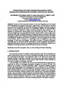
structure can be formed without manual interaction or expensive preprocessing of the input data. Compared to only view-frustum culling, our culling implementation was often more than ten times faster in our test scenes. This includes both indoor and outdoor cases. Moreover, our system always performs better than VFC (except for the special case explained in Section 5.1). Although cells-and-portals systems are primarily used for indoor environments, we have shown that they can be very efficient also in outdoor cases if additional mechanisms are used. Especially the back-wall culling technique, as it is an efficient method to quickly reject large parts of the scene that is hidden to the viewer. In the future we want to investigate the possibilities to enhance the performance of our system even further by using additional BIM-data to handle level-of-detail management during rendering.
Frustra”, in 13th Annual ACM Symposium on Computational Geometry proc., pp. 1–10, 1997. [6] G. Schaufler, J. Dorsey, X. Decoret, F.X. Sillion, “Conservative volumetric visibility with occluder fusion”, Proceedings of SIGGRAPH 2000, pages 229-238, July 2000. [7] M. Craighead, “GL NV occlusion query”, OpenGL extension specification, http://www.opengl.org /registry/specs/ NV/occlusion_query.txt [8] J. Bittner, M. Wimmer, H. Piringer, W. Purgathofer, “Coherent Hierarchical Culling: Hardware Occlusion Queries Made Useful”, Computer Graphics Forum (Eurographics 2004), 23, 3, pp. 615-624, 2004. [9] D. Sekulic, “Efficient occlusion culling”, In GPU Gems, pages 487-503, Addison-Wesley Professional, 2004. [10] H. Chih-Kang, T. Wen-Kai, C. Cheng-Chin, Y. MauTsuen, “Exploiting Hardware-Accelerated Occlusion Queries for Visibility Culling”, IEICE Transactions, 88-A(7), 20072014, 2005. [11] J. Staffans, “Online Occlusion culling”, Thesis Pro Gradu, Department of Information Technologies, Faculty of Technology, Åbo Akademi, Åbo 2006. [12] J.M. Airey, “Increasing Update Rates in the Building Walkthrough System with Automatic Model-Space Subdivision and Potentially Visible Set Calculations”, PhD thesis, UNC Chapel Hill, 1990. [13] D. Luebke, C. Georges, “Portals and mirrors: Simple, fast evaluation of potentially visible sets”, In ACM Interactive 3D Graphics Conference, Monterey, CA, 1995. [14] S. Teller, “Visibility computations in densely occluded environments”, PhD thesis, University of California, Berkeley, 1992.
Figure 11: Comparison of view-frustum culling (top) and our culling implementation (bottom).
7
References
[1] C.B. Jones, “A New Approach to the ‘Hidden Line’ Problem”, The Computer Journal, vol. 14 no. 3 Aug. 1971. [2] S.J. Teller, C.H. Sequin, “Visibility preprocessing for interactive walkthroughs”, Computer Graphics Proceedings of SIGGRAPH 91, 25(4), 61–69, July 1991. [3] A. Lerner, D. Cohen-Or, Y. Chrysanthou, “Breaking the Walls: Scene Partitioning and Portal Creation”, Pacific Graphics, 2003. [4] J.H. Clark, “Hierarchical Geometric Models for Visible Surface Algorithms”, Communications of the ACM, vol. 19, no. 10, pp.547-554, October 1976. [5] T. Hudson, D. Manocha, J. Cohen, M. Lin, K. Hoff, H. Zhang, “Accelerated Occlusion Culling Using Shadow
[15] D. Meneveaux, K. Bouatouch, E. Maisel, R. Delmont, “A new partitioning method for architectural environments”, Journal of Visualization and Computer Animation, 9(4), 195– 213, 1998. [16] D. Haumont, O. Debeir, F. Sillion, “Volumetric celland-portal generation”, Computer Graphics Forum, 22(3), 303–312, 2003. [17] S. Lefebvre, S. Hornus, “Automatic cell-and-portal decomposition”, Technical Report 4898, INRIA, 2003. http://artis.imag.fr/Publications/2003/LH03/ [18] C.M. Eastman, “Building Product Models: Computer Environments Supporting Design and Construction, CRC Press, 1999. [19] R. Arnaud, M.C. Barnes, “COLLADA: Sailing the Gulf of 3d Digital Content Creation”, AK Peters Ltd, 2006 .