EM Simulation of Installed Antenna Performance on Land, Aerial and Maritime Vehicles Frank Weinmann, Peter Knott, Thomas Vaupel Dept. Antenna Technology and Electromagnetic Modelling AEM Fraunhofer Institute for High Frequency Physics and Radar Techniques FHR Wachtberg, Germany
[email protected] Abstract—During the design process of modern land, aerial and maritime vehicles, numerous parameters have to be considered already in the planning phase to ensure that the radio, radar and navigation systems on board do not interfere with each other when in operation. Besides, surrounding structures, i.e., the platform itself or its environment, may also affect the performance of the designed antennas. For this reason, the electromagnetic simulation of installed antenna performance is an essential step in the design of antennas on platforms. This paper provides a brief overview of selected EM simulation approaches as well as examples of successful application.
I.
INTRODUCTION
Modern vehicles, aircraft and ships are equipped with a growing number of antennas and sensors for a variety of navigation, localization and communication tasks. Designing the antennas and planning the positions of antennas on a vehicle are difficult tasks as numerous antenna systems compete for the best position in the restricted space available. Contrary, the positioning of an antenna at a specific location can also have an influence on the design of the platform. Electromagnetic (EM) simulation of the installed performance of antennas on platforms is rather challenging because on the one hand the surrounding structures may be very complex in terms of geometry, materials and dimension, and on the other hand the antenna’s performance may severely be degraded in the presence of the platform. Hence, it is not sufficient to study the antenna’s properties in free space, but the influence of the platform must also be considered. In order to get reliable results for the simulated EM properties, advanced simulation tools need to be employed. The following sections provide an overview of the EM simulation tools developed at Fraunhofer FHR as well as examples of successful application of these tools to complex EM simulation tasks. II.
A. Full wave tools Full wave methods generally aim at solving the EM problem by finding a solution to Maxwell’s equations. As a prerequisite, the scenario must be discretized in an appropriate form (surface or volume discretization with the cell sizes being small as compared to the wavelength), which is one of the main difficulties with these methods. At Fraunhofer FHR an integral formulation based on the Finite Element (FE) Boundary Integral (BI) method combined with the Multilevel Fast Multipole Method (MLFMM) is developed [1]. The BI part is based on the Combined Field Integral Equation (CFIE), which is solved by applying advanced iterative solver techniques. This procedure currently enables the solution of EM problems for frequencies up to approx. 10 GHz on a fighter aircraft (length approx. 500 wavelengths). For larger scenarios, such as antennas on ships or vehicles in an environment, simulations can be performed only at much smaller frequencies, which is the reason for applying asymptotic simulation approaches in such cases. B. High-frequency tools Asymptotic or high-frequency simulation tools can provide a good approximation of EM fields in very large scenarios, i.e., if the dimensions of the relevant structures are much larger than the wavelength. Thus, a ray tracing algorithm based on the well-known Shooting-and-Bouncing-Rays (SBR) [2] is developed at Fraunhofer FHR [3, 4]. The SBR approach is used for finding relevant propagation paths, while the field strengths on these paths are calculated with appropriate Physical Optics (PO) and Physical Theory of Diffraction (PTD) formulations. This method has proved to produce rather accurate results and is most commonly used for RCS predictions of arbitrary large targets. One of the drawbacks of this method is the assumption of a point source and the neglect of the influence of the surrounding environment on the source’s radiation. Thus, this method is restricted to far field antenna problems.
EM SIMULATION TOOLS AT FRAUNHOFER FHR
Apart from employing commercially available EM simulation software, special tools are developed for simulating scenarios which are too large or too complex for standard treatment. Depending on the type of problem, both full wave and high-frequency methods are used in the design process of an antenna.
978-1-4673-5317-5/13/$31.00 ©2013 IEEE
2179
III.
APPLICATION EXAMPLES
Both full wave and high-frequency EM simulation tools have been used successfully to solve recent antenna related problems. As an example, the radiation pattern of platformintegrated antennas has been studied, which clearly showed the
AP-S 2013
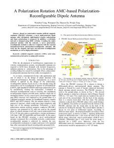
effect of the platform when comparing the integrated antenna radiation pattern to the pattern in free space. A typical example for the influence of the environment on a patch antenna integrated into the wing of a generic Unmanned Aircraft System (UAS) is investigated in [5]. The geometrical shape of the aircraft with the equivalent surface current density (real part only) excited by the antenna and a comparison between the radiation patterns of isolated and integrated antenna are shown in figure 1. In addition to airborne applications, antennas and systems located on ships have been investigated in recent projects. However, the positioning and mutual effects of antennas on maritime platforms is an even more complex class of EM problems. Due to the huge number of antenna systems on modern vessels and the very limited space on the platform, coupling between different systems cannot be neglected anymore. On the other hand, many advanced antennas are designed to operate at physical limits and their functionality may severely be degraded by interference with other antennas or with the platform itself. Thus, accurate simulation of antenna properties on platforms is an essential task in the planning phase of a platform and may result in the need to modify antenna positions or to apply additional shielding techniques. When commercial antennas are to be integrated into vehicles, it is sometimes the case that not all data required for EM analysis of the antenna-platform-interaction (e.g. exact dimensions of the radiating components, antenna input impedance, feeding structure, near-field data, etc.) are available due to the manufacturer's non-disclosure policy. In such cases it has been a successful compromise to design an "equivalent antenna" that is reconstructed from the available information based on public sources and, possibly, drawings such that the performance in terms of radiation pattern, beam-width, sidelobe level, etc. is identical to the official specifications. The equivalent antenna can then be included in the simulations to find representative results for a provisional environment. Another very complex class of EM problems is the simulation of three-dimensional propagation scenarios. An example for this class of problems is the radiation of an antenna system over terrain possibly containing various obstacles, such as buildings, wind turbines, etc., which all
(a)
might have a significant influence on the proper functionality of the antenna system. These effects might become crucial if, e.g., air traffic radar systems or air surveillance systems are considered because a significant risk might arise from malfunctioning of such systems. Due to the enormous size of the corresponding scenarios, it is obvious that threedimensional EM propagation simulations cannot be performed using full wave simulation approaches in most realistic cases. However, since the radiation source can be approximated as a point source, ray tracing approaches are rather well-suited to produce useful results with good accuracy. IV.
CONCLUSION
EM Simulation of installed antenna performance has become an essential design step during the planning phase of modern land, aerial and maritime vehicles because an increasing number of antenna systems is competing for the best positions on these vehicles. This often leads to difficult integration aspects. Using simulation results and the determined system incompatibilities, the position of the antennas can be optimized to such an extent that interference with other systems is suppressed to the greatest possible extent. Thus, investigations of this kind are meaningful and purposeful measures in the areas of vehicle design and antenna integration. REFERENCES [1]
[2]
[3]
[4]
[5]
A. Tzoulis and T. F. Eibert, “A Hybrid FEBI-MLFMM-UTD Method for Numerical Solutions of Electromagnetic Problems Including Arbitrarily Shaped and Electrically Large Objects,” IEEE Trans. Antennas Propagat., vol. 53, pp. 3358-3366, Oct. 2005. H. Ling, R.-C. Chou, and S.-W. Lee; “Shooting and bouncing rays: Calculating the RCS of an arbitrarily shaped cavity,” IEEE Trans. Antennas Propagat., vol. 37, pp. 194-205, Feb. 1989. F. Weinmann, “Ray Tracing with PO/PTD for RCS Modeling of Large Complex Objects,” IEEE Trans. Antennas Propagat., vol. 54, pp. 17971806, June 2006. F. Weinmann, “SBR Ray Tracing on NURBS for Electromagnetic Scattering Simulations,” EuCAP 2012 - European Conference on Antennas & Propagation, 26-30 March 2012, Prague, Czech Republic. P. Knott, C. Loecker, “Design of a Structure Integrated Antenna for a Small Unmanned Aerial Vehicle”, European Conference on Antennas & Propagation (EuCAP), 23-27 March 2009, Berlin, Germany.
(b)
Figure 1. Simulation of the performance of a patch antenna integrated into the wing tip of a generic UAS: (a) Shape of the aircraft with resulting equivalent surface current density (real part only) (b) Comparison of the radiation patterns (magnitude of electric field component) for isolated and integrated antenna
2180