EM Programmer's Notebook
John L. Volakis
ElectroScience Lab
David B. Davidson
Elecrical Engineering Dept. The Ohio State University 1320 Kinnear Rd. Columbus, OH43212 +1 (614) 292·5846 Tel. +1 (614) 292-7297 (Fax)
Dept. E&E E ng inee ri ng University of Stellenbosch Stellenbosch 7600, South Africa (+27) 21 8084458 (+27) 21 8084981 (Fax)
[email protected] (e·mail)
[email protected] (e-mail)
Foreword by the Editors The reflection
and transmission of plane
waves from layered
media is a standard problem in advanced undergraduate/introduc
tory
p ostgraduate
courses. Controlling the reflection
quency band is an interesting
probl em in
over a
fre·
optimization. This
A more advanced application of this type of work is in the
design of radar absorbers. Some years back, the design
consists of resistive sheets
month's contribution addresses a package developed by the authors
to address this. The authors have made the code described avai lab l e, an d we thank them for this submission.
publicly
of J auman
absorbers was reviewed in the Magazine [I). This type of absorber
1. L. J.
Du Toit,
sandwiched between dielectric layers.
"The Design of Jauman
Ab sorbers," IEEE Anten 17·25.
nas and Propagation Magazine, 36, 6, December 1994, pp.
A Graphical User Interface for Calculation of the Reflection and Transmission Coefficients of a Layered Medium Veysel Demir and Atef Z. Eisherbeni Center of Applied El ectromagnetic Systems Research (CASER) Electrical Engineering Department, The University of Mississippi, University, MS E-mail:
[email protected],
[email protected]
38677 USA
Abstract This paper presents a software package that calculates the reflection and transmission coefficients of a layered medium, and optimizes reflection and transmission in given ranges of parameters. The algorithms to calculate fields in a layered medium due to normally incident plane waves are described, and the use of a software package developed based on these algorithms is demonstrated. Keywords; Electromagnetic scattering; electromagnetic scattering by nonhomogeneous media; electromagnetic reflection; nonhomogeneous media; optimization methods; graphical user interfaces
1£££ Antennas and Propagation Magazine, Vol. 48, No.1, February 2006
113
1. Introduction
D eflec tion and transmission of electromagnet ic waves by a lay -I'-e red medium is in the scop e of undergraduate/introductory
graduate-level electro magnetics courses,
solutions [I, 2).
straightforward
-
and has well known
,
L
X
�
It is easy to develop some algo
rithms based on these solutions. Based on these algorithms, a soft
ware packag e oped, using
reflection and
and FORTRAN, in order to calculate the
transmiss ion coefficients of
a layered medium, and
to optimize reflection and transmission in given ranges of parame
.
ters The main emphasis of this package is to l et students learn how
5"p.,
---
x=O
utilizing a graphical user interface (GUl) was devel
MATLAB
[] M .. .
3
2
N
£:2:')1" 83:.1ll B,-:':'" . N�JlN BN+l,/JN+l � � !!J. � Ii. � !V, � 3- 1. � L � �l 50,A
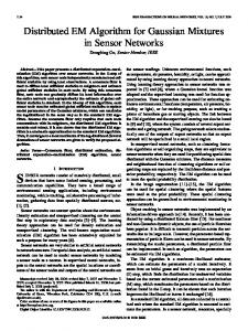
Figure
1.
d,
d,
..-�--- -
d,
d...
The layout of the layered medium,
and backward-traveliug
waves.
dN aud the forward
the optimization of a problem - commonly taught at the under graduate level - can lead to
useful
applications, and that various
a pplications Can also be attempted and fostered using the knowl edge they gained through their
then necessary to
education. A
graphical i nterface is
allow ease of use for ap plications , without a need
for reprogramming or teaching optimization at this early stage of teaching.
The developed program provides an ea
sy-to-use
order to find the
reflection
and
transmissio n
coefficients, the
forward- and backward-traveling wave amplitudes will be calcu
lated .
These waves should satisfy the continuity of the tangential
components of the ries. The
total electric and magnetic fields on the bounda
electric-field continuity equation can be written as
interface to
define and visualize the geometry of the problem, and to display the solutions for reflection and transmission coefficients, as well as
the field distributions in the medium. Furiliennore,
In
the
program
-
whereas the magnetic fiel d continuity equ ati on can be written as
helps the user define parameters to sweep, and optimizes reflection
or transmission for a given target value within the given ranges of
swept p arameters.
The term
2. Reflection and Transmission by a
kj
Layered Medium Consider a
z-polarized
x-traveling plane wave,
nonnaIIy incident on a layered medium, as
Eo, which is
shown in Figure 1. Each layer, "i", is defined by its p enn itti v ity E:i' penneabili ty J'j, electric conductivity at , magnetic conductiv ity at', and thickness dj -di-l' Backward- and forward-traveling waves in any layer j are denoted by Ai
and
waves are g iven by
iij, respectively, where expres sion s
for
these
(Ia)
EI01al,
in layer
i
is the
If
the
A- B- '(Ajejk.x Bie-jk-x) i+
i;;;; Z
J
+
I
.af)
( , E:j = E:j l 1-; -;-
, [
J'j=j.lj
(5)
1", are g iven by
,
)
.ar . 1-;-;-
(6a)
(6b)
Equations (4) can be rearranged into the forms
(7a)
sum of the forward- and
•
=mFfP{,
where (() is the angular frequency of the waves. The complex per
(7b)
backward-traveling waves, such that E-i =
is the wavenumber in l ayer i, and can be written as
mittivi ty, 10;, and the permeability,
(lb) The total field,
kj
where
(2)
medium consists of N layers that are surrounded by semi
infinite dielectric spaces on both sides, the reflection and transmis sion coefficients are expressed as
(3 a)
(3b) 114
IEEE Antennas and Propagation Magazine, Vol. 48, No.1, February 2006
This procedure can be repeated until the amplitudes in the semi infinite layer
a are solved.
Then, Equation (3) can be used to cal
culate the reflection and transmission coefficients.
Czh;
=
..Jei+dl'i+1 e-jk;.A.
In addition to Equ ations (7), w e assume
3. Reflection by a Layered Medium with PEe Termination
that
(Sa) (8b)
Using Eqnations (7) and (8), a matrix equation can be constructed.
For the configuration in Figure I, it can be written as shown in Figure
2,
and will be denoted
Equation (9).
So lutio n of
Equa
tion (9) will give the amplitudes of the forward- and backward traveling waves in all layers. However, solution of Equation (9) is
not computationally efficient, and one can construc t another algo rithm, denoted as the back-lo-tront a lgorithm, which is more effi cient.
Let's assume that that AN+1
=
0, because
Eo
is
not known, and BN+1 =1.
there is
no reflection within the
ampl itudes
N can be since examination of Equation (7) reveals that if the Ai+l and Bi+l in layer i + 1 are known, Equation (7)
can be rearranged and solved simultaneously for the and
Bi
in layer
i, such that
1
spaces on both sides. However, the previous section can also be us e d to calculate the reflection co effi cient and the fields in a layered medium terminated by a PEe (perfect electrical conductor) boundary, as well . In this case, the boundary condition for the tangential electric field components needs to b e applied,
the
equations
and algorithms demonstrated in
such that
(1la)
which leads to
(llb)
We know
right semi
infinite medium. Therefore, the wave amplitudes in layer determined,
So far, it has been assumed that the layered medium is sur
rounded by semi-infinite dielectric
amplitudes A,.
Using Equation (11) together with Equation (7), one can co ns truct a
matrix
equati o n similar to Equation (9): th i s is
the previous section still can be employed to solve this problem
more efficiently instead of solving the forward.traveling wave in layer boundary on
[CYhi
CxeiCyh; - Cxh,·Cyei -Cxhj
Equation (12),
given in Figure 3. The back-Io-front algorithm that is described in
a side,
a
Equation (12). Assuming that N, the l yer touching the PEe
has unit amplitude, i.e.,
(13)
2; ] [=�:�
-
i
=�:::J[�::] (10)
and by using Equation (13) in Equation (11), one as
backward-traveling wave ampli tu de
can find the
Bo
EO 0
Cxeo
Cyeo
Czeo
CweO
Ao
Cxho
Cyho
Czho
Cwho
Bl
0
Cxel
Cye!
Cze!
Cwel
Al
0
Cxhl
Cyhl
Czhl
Cwhl
B2
0
A2
B3
A3
0 0
0
o o
BN
Figure 2, The matrix Equation
o
o
CxeN
CyeN
CzeN
CweN
AN
CxhN
CyhN
CzhN
CwhN
BN+I
o
1
AN+l
o
(9) for the amplitudes of the forward- and backward-traveling waves in all layers.
IEEE Antennas and Propagation Magazine, Vol. 48, No. t, February 2006
115
BO
Eo
Cxeo
Cyeo
Czeo
Cweo
Ao
0
Cxho
C y ho
Czho
Cwho
BI
0
Cxel
C ye l
Cze1
ewe1
Al
0
Cxhl
Cyh1
Czh1
Cw hl
B2
0
A2
0 0 0
Figure 3. The matrix Equation (12) for a
(14) Once the amplitudes AN and
BN
are calculated, one can continue
with Equation (10) until all other amplitudes are detennined.
Furthermore, it is worth no ting that the transmission-line
analogy is another technique that is often employed to solve these kinds of problems.
B4
0
Cxe4
Cye4
Cze4
Cwe4
�
0
Cxh4
Cyh4
Czh4
Cwh4
BN
0
CxeN
CyeN
AN
0
layered medium with a PEe
In th e main parameters button
termiuation.
problem-definition window, the pops up the
optimization
optimization parameters
window ,
as shown in Figure 5. All parameters of the layers are listed in this
window. The user can choose som e of these parameters as sweep
ing parameters by clicking on the associate d check boxes. When a parameter is chosen as a swe epi ng parameter, the user can define
the range of this parameter and th e step size for the values t hat this parameter can take.
The
user can choose optimization on the
reflection coefficient or the transmission coefficient, u sing the
respective radio button.
Furthermore,
the user
can define a
target
4. Description of the Program The algorithms described
in the
p r evious sections have been
programm ed, and a software package with a
graphica l user inter GUl that is define multip le numbers
face has been constructed. Figure 4 shows the main used to define the problem. Th e user can
of layers. Each layer is defined by its relative permittivity, relative
permeability,
thickness.
The
electric
user
conductivity,
defines the
magnetic
conductivity
and
S1l!lf!1o��"nl;:r 8
�I
r
IlllCkrI�3
End FreqUII:lcy 12. , rel.£erm�I�,. -2..I'lOOIro:
#fHlqlltfidu C"·....... 41 III �rmililllint
0,1,-09'99°
�l!�;r ul"t.ara:s, ')
a1.� Cllfiod\lC11IIfIl' r",JVl -(:(lrt�U�I!'t'Ill 0.00000
o,�oo
units offrequency and length on base d By default, the layered
which the problem parameters are
.
medium is surrounded by free space on both sides. However, the
use r can choose a PEe tennination on the right boundary. The reflection and transmission
coe fficients are calculated due to plane
� t==5
waves incident on the left boundary. The user defines the frequen
window that displays the results pops up, as shown in Figure 6. The
reflection
and transmission coefficients can be displayed as
functions of frequency in this window. The magnitudes and phases
can be displayed separately, using the dropdown menu. The mag
nitude can be displayed using either a linear scale or a dB scale by using the toggle button. Furthennore, the spatial distribution of the
fields at a chosen frequency can be d i sp layed .
Any d is playe d
plot
a separate figur e by clicking the plot in s eparate in any other documents . can be exported to
figure button. This helps the user to manipUlate the plot for use
116
f.iW21 1�10 • ·4
ll;$;;;2 1->:=1 0'00 .;"00
cies of the plane waves. On clicking the plot fields button, another
:';;1
0'.0 .;".0
S----i----:,:--7:1O--,"'"S--"'''' O1S1af'lCe (millunSterS')
!orn:l�P¥:.rWl�] �
Figure 4. The GUI for defining the parameters of mUltiple lay ers of slabs.
IEEE Antennas and Propagation Magazine. Vol. 48, No.1. February 2006
where NF is the number of frequencies in the frequency range, and rn and Tn are the re fl ection and transmission coefficients at the
frequency defined by the index n. rtarget and T;arget are the target values for the reflection and transmission coefficients. The combi nation of parameters that satisfies the c onditio n in Equation (15) is considered to be optimum. Since sweeping through all pos sible combinations and cal cu latin g the reflection or transmission coeffi· cient for each combination is a time-consuming process, this task is programmed in FORTRAN rather than MATLAB, in orde r to obtai n a fast response.
o.
0.1
Once a problem is constructed and solved, it can be saved as a project file. The user thus does not need to redefine a pr ob l em that has been worked on before, and hence a [e· optimization for a different set of parameters can be started e a sily at a later time. nn
5. Sample Results
Figure Sa. Sweeping parameters for minimum reflection: Elec
trical
couductivities are euabled as sweeping parameters and
their rauges are defined.
Figure 4 sh ows a two-layer medium in free space backed by a PEC wall. The material parameters of the layers are displayed in the figure , Since the layers were backed by a PEC wall and the layer media were lossless, the incident fields were going to be reflec ted without any losses. If it is was desired to minimize the reflection from these layers, the materials should include losses. Figure 5 shows the configuration of an optimization problem that was used to find the optimum electrical conductivity values o f the layers for minimum reflection. As shown in Figure 50, the electri· cal cond uctivity parameters were enabled as s weeping parameters. After the optimization was perfonned, optimum values of the elec trical conductivities were obtained within the spec ifi ed ranges of values, as shown in Figure 5b. Figure 6 shows the amplitudes of the reflection coefficients from the l ayers using these new electrical conductivity values, over a frequency range from 8 to 12 GHz, on a dB scale.
Qjoptimizereilection
I Fliotiosepartrtefiglll'e llko:�=� '--___--"--' �
Reflection CoeffiCIent . 1 6 ,---,..---,--,---,.----, ·181'-..·..·""· ;·.. ••• .. +··"·····
Figure 5b. After sweepiug has beeu performed, optimum val ues of the parameters are determined.
for optimization. The start optimization button runs exe cuta that sweeps all combinations of parameters, and finds the c om bination that gives the closest reflection or tran smi ssio n to the target value. It returns this combination back to the optimization parameters window. The condition for the optimum value is given by value
ble code
(15a) or
.20
·22 .......
+".,......,.;. .. ........
. . r��f_:j�,· · ·v, ijj" �
,
, ......... i..........; .. ........,
8.5
. (NF� ITn
mm
-
2J '
lIarget I
(15b)
IEEE Antennas and Propagation Magazine, Vol. 48, No. 1, February 2006
Figure
6.
9
The reflection
defined in Figure 4.
9.5
10
1D�
Frequen