4th Mediterranean Conference on Embedded Computing
MECO - 2015
Budva, Montenegro
Embedded Software Testing in Research Environment. A practical guide for non-experts.
Marcin Bajer, Marek Szlagor, Marek Wrzesniak ABB Corporate Research Center Krakow, Poland
[email protected],
[email protected],
[email protected]
Abstract – Testing is nowadays one of the most important part of product development lifecycle. The goal of this publication is to provide brief description of embedded software testing in research environment. It is divided into several parts and addresses the problem of testing embedded devices not only from the source code perspective, but it also takes into consideration testing the complete system behavior. The first part of the article focuses on comparison between automatic and manual tests, trying to decide when automated tests are useful and when useless or at least not cost effective. The paper describes mainly testing industrial automation devices and some methodologies dedicated for testing this type of devices. A significant part of the paper is related to unit testing and certification tests of device’s safety critical functions. Applicability of Test Driven Development is considered. In succeeding parts, functional tests, testing support tools and test documentation are described. An important step is automatic test report generation including coverage estimation methods. The last part is related to integration tests which often require building large testing infrastructure that consist of certified equipment and dedicated testing environment. Keywords—testing, functional tests, unit tests, integration tests, software quality, test automation, manual tests, industrial equipment, embedded software verification
I.
INTRODUCTION
Testing is one of the last, and probably the most important parts of developing new product life cycle. Although, embedded software in research projects is often developed as a technology scouting or feasibility studies, it is also crucial to validate proper functionality and ensure appropriate level of reliability of such devices. For scientists who develop the software, programing is very often secondary task apart from research activities. Rarely, there is dedicated Quality Assurance (QA) team responsible for tests implementation. This publication is a practical guideline for non-experts who are eager to improve software testing techniques in their projects. It focuses on solutions and tools which fit to specific requirements of research projects. Even
though, the main area of interest of this paper is testing software for research project in industrial automation devices many of presented methodologies can be used for testing embedded software in general as well as desktop applications. II.
TYPE OF TESTS
Developing new industrial product can be divided into several parts which often overlap each other. First of all there are market requirements that determine necessity of building them. Second, there is a part of product specification (hardware selection, architecture and detailed timeline). Afterwards, there is an embedded software development section. Finally, it is a time to verify conformity of product specification with a product real functionality. This huge part is called testing. Software testing is very labor-intensive and expensive; it accounts for approximately 50% of the cost of a software system development [1]. In general, testing can be split into three major parts: preparation of test specification, implementation of test cases and finally test report generation. The first part is a key to success. It requires a lot of system knowledge to define how the product should work, what the proper reaction is and when faults or warnings should appear. As a result of this section a whole detailed test cases specification should be delivered. It is recommended to keep this document under version control system. The most important part are the test cases themselves. The main purpose of testing is to reduce risk [3]. Depending on their correctness a firmware developer can fix bugs as well as add some additional features. Every test case should be described in details, which could be used for generating final report. Report document should be some kind of a product certificate that confirms proper behavior of all devices functionalities and what has really been delivered. This document should also provide straight information about embedded firmware version.
ïðð
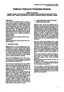
4th Mediterranean Conference on Embedded Computing Methodology and scope of tests depend on type of the product under tests, but there can be distinguished a few test categories which are related with phases of software development process. Figure 1 shows a graphical representation of this idea called V-model. In this model testers are involved from the requirements specification. Testing starts from small components and goes up to high level full system acceptance tests. Creation of a test sequences can be done in parallel with a corresponding phase of development to ensure that the project is moving forward as planned. Although, V-model is not the most commonly used one, it shows different test phases and links them with product development phases. In subsequent paragraphs all type of tests will be described in details. Requirements
Acceptance Tests
System Design
System Tests
Architecture Design
Integration Tests
Module Design
MECO - 2015
Automatic tests time to spend for creating or adapting additional testing environment, preparing tests and launching the tests Looking from the first perspective it is easy to choose the shortest one, however everything changes when going into details and treating the above assumption as only start of whole testing process. When a software or device is going to be tested only once (one software/hardware version) the manual method may be better. However the reality is otherwise. In the development process there are a lot of different versions and changes and all of them need to be tested separately. In this case, creating automated tests might be the best solution, because a time to be spent for this, is only at the beginning. Later there is merely a retest process based on ready schemas. In [6] a case study which details the cost for test automation is presented. manual testing (Am)
Cost of testing break even point
automated testing (Aa)
Unit Tests
Va
Code
Figure 1. Standard testing V-model [4]
III.
Budva, Montenegro
Vm
MANUAL VS AUTOMATIC TESTS
Da
A. Manual tests This type of tests excludes a usage of any automated tool or script. It requires tester to take over an end-user role to check whether device under test behaves correctly. The most popular manual tests are some visual reactions that are easiest to check by human, e.g. LED blinking tests, display tests, etc.
Test runs
Figure 2. Break-even point for Automated Testing
The break-even point can be calculated by comparing the cost for automated testing (Aa) to the cost of manual testing (Am) as: E(n) = Aa / Am = (Va + n * Da) / (V m + n * Dm),
B. Automatic tests This type of tests include usage of external testing environment. Sometimes this software need to be written or enhanced by the tester. The whole idea behind automatic tests is to prepare them once and launch them many times. Thus, it is applicable for big amount of different tests and in the system that is changing all the time and requires many test repetition [5]. Additional advantage, which testing environment often delivers, is a possibility of automatic test report generation and sometimes also test case coverage report. C. What is better? Cost efficiency Answer for this question is more complicated without knowing an embedded software or a device that is going to be tested. It is always a comparison of time (costs) to spend. There are several rules that define that (excluding test specification work), but in general there are: Manual tests time to spend for preparing and launching the tests
where: V - Expenditure for test specification and implementation D - Expenditure for single test execution n – number of automated test executions According to this model, benefit of test automation seems clear. It requires a much higher initial investment than manual test execution, but after reaching a break-even point there are purely profits. IV.
TEST SUPPORT TOOLS AND MAINTENANCE
Software test tools can be divided into two major categories. First group includes tools for testing code itself. In this case tools are usually strongly correlated with selected development toolchain. Lot of companies offer whole framework that includes both development and testing tools. It is often preferred solution because of good support and integration. Second group of tools is related with device features. Test tool set depends on device application domain, existence of time critical features and development process
ïðï
4th Mediterranean Conference on Embedded Computing maturity itself. As majority of devices must meet numerous and often very different features, more than one tool is needed. General approach is to use tools that do as many work automatically as possible, do not require special skills to create test cases and are able to easily and quickly modify whole sets of tests. Selected tools should be able to generate clear and useful report from performed tests automatically. When it comes to test maintenance, it is important to remember that modification in product requirements should be possible or even expected. Taking into account such a possibility can save lot of future work. Similarly as during software implementation process, test cases repositories should be used. When doing so it is easy to track changes and tests history. V.
MECO - 2015
Following internal state coverage levels are taken into account: Function coverage - during testing all function should be tested. Branch coverage - each conditional instruction should be evaluated to both true and false. Statement coverage informs about percentage of source code lines that were verified during tests. Testing all possible lines is desirable. Code coverage is often required in certification process. White and black box tests can be performed on any level of testing, but usually refers to code unit testing. Combination of both black and white box tests is often called gray-box testing [8].
CONTINUES INTEGRATION
FOR EMBEDDED SOFTWARE DEVELOPMENT
Continuous integration is a development strategy where changes are included in product mainline and tested as often as possible [7]. For committed changes, tests are performed optimally on each change to verify product stability. In practice, for embedded development it is advised to accomplish it by creating separate build-machine that runs unit tests, compiles and after that deploys firmware and runs automatic tests. Due to the different projects sizes, various building frequencies are used, from nightly up to weekend builds. It is worth remembering that defect costs are lower if less time will pass from committing up to detection. What is more as every change in source is tracked it is often possible to find the reason of test fail without debugging. Scheduled build
Commit Code repository
Development
Build
Report Testing
Deployment on target hardware
Figure 3. Continues integration workflow
VI.
BLACK AND WHITE BOX TESTING
First type of unit testing is black-box testing in which knowledge of internal structure of tested module is not required. This kind of tests assumes only that with given inputs a tested unit will product expected results. It is enough to create tests basing on product specification. In contrast, white-box tests are created using the knowledge and understanding of internal structure of tested module. When designing white-box tests it is required to examine source code and run tests with input which will bring desired internal states and in this way test as many of them as possible.
Budva, Montenegro
Black box
White box Figure 4. White and black box tests
VII. UNIT TESTS A. Unit tests and Test driven development Unit testing is a software testing method that is based on verifying correct behavior of invalid part of source code, usually each function [9]. It is one of the lowest level possible test. That is why in development processes, unit tests should be performed in first row. When once created can be used in safe refactoring by automatically checking regression each time run. Unit tests are often used as an executable documentation that provides warranty that created code is compatible with it. [11]. Additional benefit may be design improvement. It is especially visible when test-driven development process is used. In this approach unit test is created in advance to writing code. Then minimal amount of code is written to pass them and when passed, the code can be safely refactored. This improves design by not including code that is not required and by assuring relative code separation. Embedded development differs in many aspects from standard software development. Algorithms that work properly compiled for desktop computers, often do not need to do the same on target hardware. Running test in parallel with software development is often hard due to the time that it takes to deploy firmware or even impossible when it is too expensive to provide each developed in its own hardware. Also there is often a need to mock some components that are not a part of tested unit, but are required for the device to run properly. This kind of mocking is very difficult in embedded environment. Developer needs to remember that unit tests will not find majority of bugs related with time dependencies or ones that involve interrupt handling.
ïðî
4th Mediterranean Conference on Embedded Computing B. Tessy – Unit testing of embedded software Tessy is an example of a testing environment tool for creating automatic unit tests. It is a PC tool that automates unit testing for C code of embedded software. It provides a possibility to test each specific C function in complete isolation from all other functions.
MECO - 2015
Budva, Montenegro
required to program timer in PLC logic which is triggered on DI/communication bit change.
Test engineer Test specification
Test design platform (OPC client) System specification
Test Execution Report
Ethernet
Test Coverage Report
OPC server
PLC
Analog ouputs Digital outputs Communication fieldbus
Digital inputs
Analog inputs
DUT
Figure 5. Tessy classification tree
Figure 6. Functional tests implementation
Tessy can automatically schedule and execute test cases, evaluate the test results and generate report in several, most typical formats. A big advantage of using this software is a code coverage viewer showing a path through the software for the single highlighted test case. Tessy does not have built-in compiler which is a very good solution because it only supports external C language compilers and all embedded microprocessors. VIII. FUNCTIONAL TESTS
Modified version of this approach is presented in Figure 7. In this case PLC was used in two rules first, as before, it is a gateway between DUT and test platform and second it is used for simulating device on DUTs expansion bus. In PLC memory buffers with different types of telegrams were defined, based on implemented logic PLC response on DUTs telegram with the content of appropriate buffer. Additional assumption is that in DUTs source code communication telegrams are defined in form of structures. Test design platform is able to parse it to help test engineer filling telegram buffers in PLC.
Functional verification of an embedded device is done to ensure that the system fulfils its requirements. It is based on black box testing approach. In contrast to unit and component testing it does not require any knowledge about system internals [10]. Functional tests are meant to validate device behavior against its specification. Figure 6 shows in practice how functional tests of industrial automation device can be realized. To interact with the Device Under Test (DUT), Programmable Logic Controller is used (PLC) this allows to handle most of industrial fieldbuses used at the factory level and easy simulates inputs to DUT and reads its outputs. OPC technology is used for interacting with PLC. This allows to split tests environment into two parts. First part is a dedicated test engineering environment which is basically a PC application to prepare and execute test sequences. Second part is a test rack where DUT and PLC are installed. In theory, both parts can be placed in distant locations, because Ethernet is used for interconnection. In this configuration PLC is used only as a proxy device which just tunnels image of DUT inputs and outputs. Test logic is created in PC application by a test engineer based on test specification. To provide system description in user-friendly version (i.e. text instead of binary data) test design platform parses system specification prepared in special form (i.e. Excel files).
The main drawback of presented solution is performance of OPC server. In presented test system refresh rate of OPC was limited to 100ms. In case fast reaction of test system is required, additional logic need to be implemented in the PLC software. For example, for testing DUTs response time it is
Communication fieldbus PLC/simulator of DUT expansion module
DUT
OPC
DUT expansion module bus (RS 485)
Test design platform
struct { uint8 Address; enum FunctionCode; uint32 Data; uint16 CRC; } Telegram1; ...
DUT source code
Figure 7. Modified functional tests implementation
Modification of methodology presented in Figure 8 was done to perform integration tests of DUT ant DUTs expansion module. The stream of communication was sniffed by the PC. To distinguish telegrams it was assumed that each message is shorter than maximal telegram length and ends with two bytes CRC. In the end test engineer could filter telegrams and verify its content. OPC
PLC Communication fieldbus DUT
struct { uint8 Address; enum FunctionCode; uint32 Data; uint16 CRC; } Telegram1; ...
Test design platform Expansion bus sniffer
DUT expansion module bus (RS 485)
DUT expansion module
Figure 8. Functional validation of DUTs expansion module
IX.
FUNCTIONAL SAFETY FOR EMBEDDED SYSTEMS
This chapter presents requirements for testing, verification and validation of the embedded systems from the functional safety perspective.
ïðí
4th Mediterranean Conference on Embedded Computing
MECO - 2015
A. Definitions Functional Safety is a part of the overall safety related to the equipment under control and its control system that depends on the correct functioning of the safety-related systems and other risk reduction measures [12].
Validation planning
1) Verification: the objective of this clause is to demonstrate by review, analysis and testing that the required outputs satisfy the defined requirements for the appropriate phase of the safety lifecycle identified by the verification planning [6]. It is also important to create a plan that would select appropriate techniques and measures to avoid systematic failures. For each application software, there must be a completed code review form.
Lifecycle Phase PHASE INPUTS Objectives and Requirements
Phase Activities
VERIFICATION Completness and Correctness
Validation
Factory Acceptance Test Specification
FAT Testing of System
Site Acceptance Test Specification
Safety Integrity Level (SIL) is a discrete level (one of four) that specifies the probability of safety-related system satisfactorily performing the specified safety functions under all the stated conditions within a stated period of time [13].
In general it is divided into four major parts:
Earlier Lifecycle Phases
Safety Requirements Specification
Safety Instrumented System (SIS) is designed to respond to conditions, where the embedded device works, that may be hazardous and must generate the correct outputs to prevent the hazard or mitigate the consequences.
B. Verification, Validation, Audit and Assessment Overall safety lifecycle process distinguishes dedicated phase to decide whether the build system meet the requirements of SIS and granted SIL.
Budva, Montenegro
SAT Testing of System
Figure 10. Validation Model
Factory Acceptance Tests (FAT) demonstrate that the application software and project specific hardware have been configured in accordance with client requirements and that the tests are an effective verification method. Site Acceptance Tests (SAT) define how an organization shall test the Safety System after installation at site to demonstrate the following: The system has been delivered and installed without damage or change in basic operation and performance The system has been correctly installed, interconnected and connections to power and earth are correct 3) Functional Safety Audit: systematic and independent examination to determine whether the procedures specific to the functional safety requirements comply with the planned arrangements and are suitable to achieve the specified objectives. No specific judgment of functional safety and integrity is done. 4) Functional Safety Assessment (FSA): investigation, based on evidence, to judge the functional safety achieved by one or more safety-related system. The FSA is a mandatory requirement and shall be applied to all phases of the safety lifecycle. X. INTEGRATION TESTS
PHASE OUTPUTS
Figure 9. Verification Model
2) Validation: the objective of this clause is to validate, through inspection and testing, that the installed and commissioned safety instrumented system and its associated safety instrumented functions achieve the requirements as stated in the safety requirements specification.
Term integration tests can be confusing since they can be understood as testing of interactions inside final system where the developed device is installed or integration testing of software parts as elements of complete subsystem. Therefore integration tests are often split between subsystem level integration tests and system level integration tests. Subsystem-level integration tests are required in every project that contains even few independent modules. Testing correct behavior of each component separately is helpful, but not enough to confirm correct behavior of completed device. Usually this type of tests is carried in similar way as whitebox test but without inspecting modules inside structures, only as many as possible modules interoperability cases. System-level integration is especially important for embedded devices. It is very common that implemented
ïðì
4th Mediterranean Conference on Embedded Computing device needs to cooperate with already existing devices, often produced by other companies. Verification if our product is working with market devices is crucial. Tests on this level are usually conducted by preparing special test environment with conditions similar with real life installation and run typical usage scenarios. A practical example of system-level integration tests can be a test of interoperability of automation protocols gateway. Expected behavior is that all major companies controllers will be able to connect to slave devices using this gateway. System integration in this case would require running some functional tests in several such environment. As a word of caution it is worth to ensure proper behavior even if all devices are declared as having protocols implemented in accordance with the specification. During system-level integration tests it is worth performing also stress tests. In those tests it is needed to verify if product performs as expected in maximum network load, when communication is interrupted by other devices, when there is maximum number of slave devices connected etc. On this test level detecting source of bug gets very hard. That is why it is important to do as much testing on unit level as possible. XI. CERTIFICATION TESTS Additionally of ensuring that product meets requirement specification, tests are often used to obtain certification. Those tests are usually carried out in external test laboratory. They may concern hardware, software and functional tests. EMC (Electromagnetic Compatibility) tests can be an example of hardware certification tests. Their role is to verify that device will not produce electromagnetic interferences that could interrupt other devices of work. Example of software test that is required for certification, is ATEX [14]. In general, it is a set of rules that each device used in explosion endangered environments need to conform. A part of the process of obtaining a certificate is presenting the reports from unit tests of embedded firmware. In addition, implementation process needs to be documented in accordance to required standards. Functional tests are most common ones regarding certification. Example of such tests are those performed by Profibus Organization. During this type of tests all features
MECO - 2015
Budva, Montenegro
specific for tested protocol are verified and also basic integration tests are performed. As certification tests tend to be expensive, it is recommended to run pretests before shipping device for certification. XII. SUMMARY To sum up, this paper provides only a brief description of chosen aspects of testing software for embedded devices. Knowledge of presented techniques is strongly recommended for every scientist who make software for embedded devices. In part where functional tests are described focus was placed on testing software for industrial devices. Selected techniques for testing such devices were described, but it is easy to accommodate them to testing other types of embedded software. REFERENCES [1] [2] [3] [4] [5] [6]
[7]
[8] [9] [10] [11] [12] [13] [14]
ïðë
B. Korel, Automated Software Test Data Generation, IEEE 1990. G. J. Myers, C. Sandler, T. Badgett The Art of Software Testing, 3rd ed., Wiley, 2012. N. Jenkins A software Testing Primer. And introduction to Software Testing, 2008, unpublished. K.H. Pries, J.M. Quigley, Testing Complex and Embedded Systems, CRC Press, 2010 L. G. Hayes, The Automated Testing Handbook, 2nd ed., Software Testing Inst, 2004. V.N. Maurya, R. Kumar Analytical Study on Manual vs. Automated Testing Using with Simplistic Cost Mode, ISSN, 2277-7040, Volume 2 Issue 1, 2012. W. Bereza, M. Fletcher, M. Karlesky, G. Williams, Mocking the Embedded World: Test-Driven Development, Continuous Integration, and Design Patterns, Methods & Tools, 2007. I. Jovanovi , Software Testing Methods and Techniques, 2008. IEEE Standard for Software Unit Testing, ISBN 1-55937-672-4, SH10587, 1986. J. Zander, I. Schieferdecker, P. J. Mosterman, Model-Based Testing for Embedded Systems, CRC Press, 2011. C. Kaner,, "What Is a Good Test Case?", STAR East, 2003. IEC 61508-4:2010, edition 2.0, part 4, clause 3. IEC 61511-1:2003(E), edition 1, part 1 clause 7. Directive 94/9/EC on equipment and protective systems intended for use in potentially explosive atmospheres (ATEX), European Parliament and the Council, 1994.