SAE TECHNICAL PAPER SERIES
2004-01-1593
Model-Based Testing Of Embedded Automotive Software Using Mtest Klaus Lamberg, Michael Beine, Mario Eschmann and Rainer Otterbach dSPACE GmbH, Paderborn, Germany
Mirko Conrad and Ines Fey DaimlerChrysler AG, Berlin, Germany
Reprinted From: In-Vehicle Networks and Software, Electrical Wiring Harnesses, and Electronics and Systems Reliability (SP-1852)
2004 SAE World Congress Detroit, Michigan March 8-11, 2004 400 Commonwealth Drive, Warrendale, PA 15096-0001 U.S.A. Tel: (724) 776-4841 Fax: (724) 776-5760 Web: www.sae.org
All rights reserved. No part of this publication may be reproduced, stored in a retrieval system, or transmitted, in any form or by any means, electronic, mechanical, photocopying, recording, or otherwise, without the prior written permission of SAE. For permission and licensing requests contact: SAE Permissions 400 Commonwealth Drive Warrendale, PA 15096-0001-USA Email:
[email protected] Fax: 724-772-4891 Tel: 724-772-4028
For multiple print copies contact: SAE Customer Service Tel: 877-606-7323 (inside USA and Canada) Tel: 724-776-4970 (outside USA) Fax: 724-776-1615 Email:
[email protected] ISBN 0-7680-1319-4 Copyright © 2004 SAE International Positions and opinions advanced in this paper are those of the author(s) and not necessarily those of SAE. The author is solely responsible for the content of the paper. A process is available by which discussions will be printed with the paper if it is published in SAE Transactions. Persons wishing to submit papers to be considered for presentation or publication by SAE should send the manuscript or a 300 word abstract of a proposed manuscript to: Secretary, Engineering Meetings Board, SAE. Printed in USA
2004-01-1593
Model-based Testing of Embedded Automotive Software using MTest Klaus Lamberg, Michael Beine, Mario Eschmann and Rainer Otterbach dSPACE GmbH
Mirko Conrad and Ines Fey DaimlerChrysler AG
Copyright © 2004 SAE International
ABSTRACT
MODEL-BASED SOFTWARE DEVELOPMENT
Permanently increasing software complexity of today’s electronic control units (ECUs) makes testing a central and significant task within embedded software development. While new software functions are still being developed or optimized, other functions already undergo certain tests, mostly on module level but also on system and integration level.
Within automotive electronics development, a modelbased development process has been established over the last years. Using modelling, simulation and code generation tools is a common way to develop and implement new vehicle functions.
Testing must be done as early as possible within the automotive development process. Typically ECU software developers test new function modules by stimulating the code with test data and capturing the modules’ output behavior to compare it with reference data. This paper presents a new and systematic way of testing embedded software for automotive electronics, called MTest. MTest combines the classical module test with model-based development. The central element of MTest is the classification-tree method, which has originally been developed by the DaimlerChrysler research department. The classification-tree method exists for several years now and is mostly used for C-code testing. Now, it has been adopted to the needs of a model-based development process for embedded systems. MTest opens a new way of assuring quality for embedded software, that is especially designated for automotive software developers. This paper demonstrates, how MTest is used to test automotive software from model-in-the-loop over software-in-the-loop down to processor-in-the-loop testing. Additionally, test scenarios once developed using MTest can be reused in a hardware-in-the-loop environment. Thus, MTest provides a means to automatically test automotive software within the whole development process.
Therefore the control function to be developed is described by the means of simulation tools like MATLAB/Simulink/Stateflow (function design). Such tools provide a graphical way of describing functions and systems. This includes block diagram notations as well as state charts. Using Rapid Control Prototyping (RCP) systems, the new functions can be proven in the real vehicle or on a dynamometer. Therefore, automatic code generation is used to generate C code from the function model. This code is run on powerful real-time systems. Such systems are connected to the real plant by special I/O. Changes can be made directly to the function model and tried out immediately by generating code once again. Implementation of the function on a production ECU is done by automatic production code generation. However, the requirements on a production code generator are much higher then for RCP. The generated code must be highly efficient, error-free, reproducible, and well documented. An example for a production code generator is TargetLink [1].
MODEL-BASED TESTING Today’s way of automotive function and software developing using RCP is characterized by an experimentational way of working. Systematic and automated testing doesn’t play an important role so far. Additionally, testing tools are missing today, which provide special methods for the testing tasks in the specific process stages. This is true especially for the early stages of function and software development. The model-based testing process
as described in the following lays a major focus on systematic and automated testing in the early stages. It also includes ECU testing activities which are typical for the later development stages.
Testing the Function Code The next step is testing the actual function code. This can be done on a host PC (software-in-the-loop, SIL) or on the target processor (processor-in-the-loop, PIL).
THE MODEL-BASED TESTING PROCESS ECU Integration The model-based testing process (Figure 1) describes the different activities within the whole automotive electronics development process from a testing point of view. This includes testing in the early function development as well as ECU testing later in the process.
Figure 1: Model-based testing process Testing the Logical Model Testing the logical model means systematic and automatic testing of an executable model of the function or controller to be developed. This model is the test object or unit under test (UUT). The test can be done open loop or closed loop using a model of the plant (model-in-theloop, MIL). Testing the Implementation Model The functional model has to be prepared for implementation. Software design information has to be added. Functional models are usually floating-point models whereas the implementation in C is often realized using fixed-point arithmetic. Thus scaling information, implementation data type, LSB and offset, is to be specified for each block output signal and parameter. The behaviour of the fixed-point implementation has to be compared with the behaviour of the functional model. It has to be checked if the quantization effects introduced are acceptable. This verification is done by simulation since the equivalence between the two representations can not be formally proved. The implementation model can also be tested in a closed loop environment (MIL).
The generated function code has to be integrated with the overall ECU software. ECU integration means integration with other function modules, the operating system and I/O drivers. Although, this step isn’t a test step in the sense of the model-based test process, the integration is already to be taken into consideration and prepared when creating the implementation model. Special focus is laid on functions and global variables that are defined or to be called and re-used outside of the implementation model. Their definitions and declarations must match the ones in the external code. The operating system integration depends on the scope of the model. If the model only describes a single feature that will be part of one task in the ECU then the call of the generated function is usually manually implemented in the OS frame. If the model has a wider scope and consists of multiple functions and tasks then operating system objects are already specified in the model. For example, dSPACE offers a special module for its production code generator TargetLink to support and automate the integration with OSEK operating systems. Task distribution, intertask communication and other OS properties can be specified directly in the model. The generated code then already contains the corresponding OSEK keywords and can be integrated with the OSEK OS without any further manual integration work [2]. ECU Testing ECU testing typically is done using hardware-in-the-loop simulation (HIL). Therefore the ECU prototype is connected to a real-time simulation system simulating the plant. Corresponding ECUs are also simulated rest bus simulation). Almost always, ECU testing is black box testing where the inputs are stimulated and the outputs are monitored. System Testing System testing means to test the ECU in its direct technical environment using HIL simulation. Therefore the ECU is at least partially integrated with other ECUs and its behavior is tested in conjunction with other ECUs. Integration Testing Finally, all ECU of a single vehicle are integrated and the whole network system is tested. This is called integration testing. HIL simulation is used more and more also for integration testing.
The testing tasks described above are different from each other. In the following, a testing methodology is described, which supports especially the early phases, i.e. testing the logical model, testing the implementation model and testing the function code. Additionally, test data once developed using this methodology can also be used in hardware-in-the-loop simulation. THE MTEST APPROACH The MTest (MTest = “Model-based Testing”) methodology complements model-based development with a method for systematic test definition. The starting point of the MTest testing process is a model of the function or controller to be developed, implemented in Simulink or TargetLink. Based on the interface of the logical model, and by using the classification-tree method, the function developer can derive test scenarios systematically and describe them graphically. With the graphical representation the user gets visual information about the test coverage. Test coverage indicates, how well the test cases cover the range of possible test input combinations and is therefore the most important test metrics. The MTest process consists of different testing activities building the base for systematic testing and therefore support for a systematic testing procedure. The testing activities are shown in Figure 2 schematically. They are described more detailed in the following paragraphs.
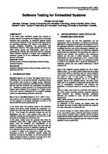
SYSTEMATIC TEST DEFINITION The MTest approach to model-based testing utilizes a specific instance of the classification-tree method with extensions for embedded systems (CTM/ES) for the systematic test definition, [4], [5]. The classification-tree method is a black-box partition test design technique, where the input domain of the test object is split up under different aspects usually corresponding to different input data sources. The different partitions, called classifications, are subdivided into (input data) equivalence classes. Finally different combinations of input data classes are selected and arranged into test sequences. SELECTING THE TEST INTERFACE A subsystem within an .mdl file is to be selected first in order to be able to subsequently relate the test scenarios to the respective units under test (UUT), i.e. Simulink or TargetLink model subsystems. The interface of the subsystem to be tested will then be analyzed automatically, and the information relevant to testing will be extracted (model extraction). The input of the subsystem to be tested forms the potential input variables for the test. It is consequently called a ‘potential test interface’. There is no necessity, however, of using the potential test interface for the test object stimulation on a one-to-one basis: Fed back values, for example, do not need to be predetermined as they are generated by the system environment. On the other hand, it is often easier to describe a complex input signal by means of (additive or multiplicative) superposition of two sub-signals. In this case, instead of the potential interface signal the two sub-signals would be described. The values actually used for the simulation are referred to as ‘effective input interface’. If there are differences between the potential and the effective interface for a certain test object they have to be mapped onto each other.
effective input interface
potential input interface SteeringWheelAngle
Figure 2: Model-based testing activities
AccPedalPosition BrakePedalPosition ...
As an alternative to using the classification tree method, it is possible to use existing data as test data. This is called “direct testing”. To illustrate the MTest approach to model-based testing we use the example of a vehicle dynamics control (VDC) system that controls the vehicle motion in physical limit conditions (cf. [3]).
ThrotteTorque BrakeTorques
YawRate LateralAcceleration
...
WheelSpeeds
VDC
VehicleAndRoadModel
Figure 3: Potential and effective test interface
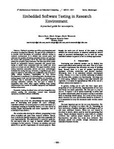
The VDC-software’s behavior is determined, among other things, by the steering-wheel angle, the accelerator and brake pedal positions, the yaw rate, and the fourwheel speeds. These signals form the example’s input interface. If a closed loop test with typical driving maneuver is to be performed, however, only the driver inputs SteeringWheelAngle, AcceleratorPedalPosition and BrakePedalPosition have to be stimulated. These values form the effective input interface. The remaining input values are implicitly determined by the vehicle/road model. (Figure 3). CREATING THE CLASSIFICATION-TREE Based on the effective test interface MTest automatically outputs a first, incomplete instance of a classificationtree called basic tree (Figure 4): The name of the unit under test itself forms its root node (here: “VDC”), the signals of the effective input interface (e.g SteeringWheelAngle) are denoted as classifications below the root node. In a second step, the generated classifications must be disjointedly and completely partitioned into (equivalence) classes which are suitable abstractions of individual input values for testing purposes. The partitioning aims to achieve a selection of the individual classes in such a way that they behave homogeneously with respect to the detection of potential errors. That is, the unit under test behaves either correctly or erroneously for all the values of one class (uniformity hypothesis). An heuristic procedure has proved successful in approaching this ideal partitioning as much as possible in practice. The inputs’ data type and value range provide first valuable clues to partitioning: Where real-valued data types with minimum and maximum values established are concerned, it is possible, for example, to create a standard class each for the boundary values, for the value of zero and for those intervals in between. Alternatively, real-valued data types could be partitioned into same size sub-intervals. Similar data-type specific standard classifications can also be utilized for different data types. As soon as information on the data types or value ranges of the input variables is available to MTest, the data-type specific standard classifications for different data types can be generated automatically (cf. [6]).
VDC
Inputs
SteeringWheelAngle
-360
AccPedalPosition
360 ]-360,0[
BrakePedalPosition 100
100
]0,360[ 0
...
]0,100[
]0,100[ 0
0
Figure 4: Basic classification-tree Figure 4 depicts the automatically generated basic classification tree for the VDC example: It contains the automatically generated standard partitioning for real-valued signals for the 3 effective interface input signals. The following five classes arise for the signal SteeringWheelAngle, which can take on values from the range of –360° to 360°: –360, ]-360, 0[, 0, ]0, 360[ and 360. In this case, ]x, y[ denotes an interval, open on both sides, with the boundary values x and y. As a rule, the data-type specific standard classifications are not detailed enough for a systematic test. They have to be refined or modified manually in order to approach a partitioning according to the uniformity hypothesis. The quality of the specification and the tester’s experience are crucial in this respect. The evaluation of the pedal positions (described as percentages in the VDC software) recognizes a pedal as depressed only if it is activated above a certain threshold value PedMin. The pedal values above and below the threshold should therefore be considered separately because behavior is expected to differ. As the acceleration force also influences the system behavior, there has to be an additional distinction between light (pedal position< 50%) and strong (pedal position ≥ 50%) pedal operation. The result is a final partitioning of the pedal positions into the classes 0, ]0, PedMin[, PedMin, ]PedMin, 50[, [50, 100[ and 100. In this case, [x, y[ denotes an interval which is closed on the left side and open on the right side. The partitioning of SteeringWheelAngle has been refined as to subsume all 90° sections in one class respectively (Figure 6). DEFINING TEST SEQUENCES Based on the input partitions, test sequences can be determined. These sequences specify how the behavior of the regarded unit under test should be tested. The domain for the description of test scenarios is provided by the completed classification-tree. The tree is used as the head of the combination table. Each sequence captures a data abstraction of the unit under test's inputs. Hence, it describes – largely independent from detailed or precise data – what is to be tested. In order to represent test sequences in an abstract way, they are decomposed into individual test steps. According to their
temporal order, the steps build the rows of the combination table. Such a sequence of test steps is called a test sequence. Each test step defines the inputs of the UUT over a certain time span. The time spans are listed in a separate column on the right-hand side of the combination table. The beginning and end points of these time intervals are called synchronization points, since they synchronize the stimuli signals at the beginning and end of every test step. The description of the values of the single stimuli signals for each test step takes place by marking a class defined for this signal in the classification tree. This is indicated in the middle part of the combination table. The stimulus signal in the respective test step is thus restricted to the part-interval or single value of the marked class. The combination of the marked input classes of a test step determines the input of the UUT at the respective synchronization point. The values of the stimuli signals between the synchronization points are described by basic signal shapes. Different signal shapes (e.g. ramp, step function, sine) are represented by different arrow types which connect two successive markings in the combination table. In this way stimuli signals can be described in an abstract manner by the means of parameterized, stepwise defined functions [4].
Figure 5: Driving maneuver “lane change” Figure 6 shows the lane changing maneuver of Figure 5 as a test sequence in the combination table. After an acceleration phase the steering-wheel is first turned in a 90-degree angle to the left, then, the steering wheel is turned to 90-degree in the opposite direction and back into the original position. After a hold phase the wheel is turned by 90-degrees to the right, back to the left and back into the neutral position. Here, a solid line as arrow type means a ramp shaped change of the signal value, no (visible) transition means a skip of the signal value at the end of the interval. The accelerator pedal ramps up during the acceleration phase. The adjusted pedal position is held and at the end of the test sequence the pedal is released again. At the same time, the brakes areactivated. A dashed line as an arrow type denotes a change of the signal value in the form of a sine half-wave.
Figure 6: Classification-tree with test sequence Further test sequences can be described underneath the classification tree by using the procedure above mentioned. After the determination of test sequences has been completed, it is necessary to check if they ensure a sufficient test coverage. At this early stage of the testing process, the CTM/ES already allows the determination of different abstract coverage criteria based on the classification tree and the test sequences: A requirements coverage analysis can verify whether all requirements of the requirements specification are covered sufficiently by the test sequences. In general, a n:m-relationship exists between requirements and test scenarios. In the course of the analysis it is necessary to prove that every requirement is being checked by at least one test scenario and that the existing test scenarios are adequate to test the respective requirements. Furthermore, the CTM/ES supports a range coverage analysis. This analysis checks the sufficient consideration of all equivalence classes defined in the classification tree in the test sequences. This check can be executed, according to the respective application case, by using different, so-called classification-tree coverage criteria (CTC) (cf. [5]): •
•
•
The minimum criterion (CTCMIN) requires every class of the tree to be selected in at least one test step. The minimum criterion is usually accomplishable with a few test sequences, the error detection rate, however, is rather low. The maximum criterion (CTCMAX) requires every possible class combination to be selected in at least one test step. The fullfillment of the maximum criterion should bring a high error detection rate. Because of the combinatorical “explosion”, this criterion is only practicable when having a small number of classes. The n-wise combination criteria (CTCn) present a compromise. Here, it is necessary to ensure that every possible combination of n classes is selected in at least one test step. For example, a pair-wise combination of classes (CTC2) is practicable.
The selection of appropriate criteria has to take place in a problem-specific way within the frame of the test planning. If the criteria defined beforehand are not sufficiently fulfilled, additional test steps / test sequences need to be added until the required criteria are fulfilled.
TEST CONFIGURATION TEST DATA REFINEMENT The test scenarios gained by using the classification method only contain abstracted stimulus information, because only equivalent classes have been used, but no specific data. Thus, in a second step, the test data is instantiated by the means of definite numbers. The borders of the classes of the classification tree are used as signal constraints, wherein the actual signal traces can vary. Instantiating the test data is done using the signal editor shown in Figure 7. The borders of the equivalent classes form the constraints of the value ranges at the respective sample points. By default, MTest uses the mean values of the intervals in the classification tree. In this example at the sample point 3 sec, the value has been edited within the constraints (cf. the marked cell at the bottom).
Figure 8: Editing imported test data ASSIGNING TEST DATA TO THE MODEL INTERFACE When using the classification tree method, the assignment of the generated test data to the inputs of the UUT is done automatically. Using direct testing, the data must be explicitly assigned to the inputs of the UUT (Figure 9). Once the assignment has been defined by the user, MTest checks for the consistency in terms of signal type, signal complexity and signal dimension.
Figure 7: Signal editor with interval borders As an alternative to the classification tree method, MTest allows to use real data as test data. This is called “direct testing”. Using direct testing, it is possible to import real measurement data, gained e.g. from a driving or a dynamometer experiment. This data can be used to stimulate the UUT (Figure 8).
Figure 9: Assignment of test data DEFINE REFERENCE DATA AND EVALUATION CRITERIA Test and simulation results can also be compared to reference data. Reference data can be a result of former test runs, or even be any kind of measurement data which can be imported.
In a further configuration step, the user can define the evaluation rule, i.e. how the results shall be compared with reference data. Therefore the user can select out of a set of evaluation criteria, including absolute and relative difference. This set can also be extended by the user.
TEST EXECUTION AND EVALUATION GENERATE TEST HARNESS
Figure 11: Dialog to define the simulation modes
Figure 10: Generated test harness in Simulink The test scenarios which have been defined using the classification tree method or by importing data can be applied to all of the three representation forms of the UUT: to the logical model, to the implementation model and to the function code. Therefore, MTest supports executing the tests in Simulink and in the different TargetLink modes. For the execution, a test harness in generated automatically in Simulink (Figure 10) and a copy of the Simulink or TargetLink model of the UUT is inserted into it. MTest can activate the required TargetLink simulation mode – floating-point simulation on the host PC („TargetLink MIL“), production code simulation on the host PC („TargetLink SIL“) and production code simulation on the target processor („TargetLink PIL“) – and if necessary start the TargetLink production code generation. Figure 11 shows, how the desired modes in which a test sequence is to be executed, can be selected by the user. Figure 12 shows how the different modes are represented in an MTest project tree.
Figure 12: MTest project tree with different simulation modes RESULT MANAGEMENT AND REPORT GENERATION Once the test has been executed, the test results are collected automatically and displayed instantly. The amount and the depth of result information can be adjusted by the user.
The enormous number of tests for a single function or ECU is not only to be developed and executed. All the tests must be stored and administrated consistently, so that they can be performed repeatedly (“regression testing”) and reproduced at any time. The large amount of test results – each test run produces a new result instance – must be stored persistently. Storing, maintaining and administrating this large amount of tests together with the test data and the test results require powerful means to manage test projects.
Figure 13: Result browser
Figure 15 shows an example of a test project structure in AutomationDesk. The test data and the test results together with the test sequences are displayed in project trees. The upper part of the tree contains an MTest project, the lower part contains a typical HIL project. It is obvious that test data which have been gained e.g. by using MTest can be reused in an HIL simulation.
The results are structured hierarchically and displayed as a tree (cf. Figure 13). The result tree can include any data item and any test which has been done in the different simulation modes. The user can navigate through the tree and view all details. For signal traces, the user can also generate plots immediately. Finally, it is possible to generate test reports based on the result information. Test reports can be produced in different formats, e.g. HTML or PDF.
MTEST IN AUTOMATIONDESK
Figure 15: Test project examples in AutomationDesk
CONCLUSION
Figure 14: AutomationDesk Although the testing tasks and activities within the different process stages vary from each other very much, a testing environment must combine and integrate all these approaches under one common roof. this can be achieved, if all the necessary elements of the process are provided by one testing tool. An example is the tool AutomationDesk, [7], [8] (Figure 14).
This paper describes a method and a tool for systematic and automated testing, called MTest. Based on a modelbased testing process, MTest especially allows for model-based testing in early function and software development. The core of MTest is the classification-tree method, providing a systematic way of developing test scenarios graphically. Since MTest is an integral part of the test automation environment AutomationDesk, test scenarios once developed using MTest can be reused in later development stages, e.g. when testing real ECUs or ECU prototypes by the means of hardware-in-the-loop simulation. AutomationDesk together with MTest therefore build a testing environment supporting the whole model-based development process.
REFERENCES 1. dSPACE TargetLink poduct information: http://www.dspaceinc.com. 2. Köster, L.; Thomsen, t.; Stracke, R.: Connecting Simulink to Osek: Automatic Code Generation for Real-Time Operating Systems with TargetLink. SAE 2001,March 5-8,2001,Detroit, Michigan, USA Technical Paper 2001-01-0024 3. v. Zanten, A.; Erhardt, R.; Landesfeind, K.; Pfaff, G.: Stability Control. In: R. K. Jurgen (Ed.): Automotive Electronics Handbook. 2nd edition, Mc Graw-Hill, 1999 4. Broekman, E.; Notenboom, E.: Testing Embedded Software. Addison-Wesley, 2003 5. Grochtmann, M.; Grimm, K.: Classification Trees for Partition Testing. Software Testing, Verification and Reliability, 3, 63-82, 1993 6. Conrad, M.;Dörr, H.; Stuermer, I.; Schuerr, A.: Graph Transformations for Model-based Testing. Proc. of Modellierung 2002, Tutzing (D), März 2002 7. Lamberg, K., Richert, J.; Rasche, R.: A New Environment for Integrated Development and Management of ECU Tests. SAE 2003-01-1024, 2003. 8. dSPACE AutomationDesk product information: http://www.dspaceinc.com .
CONTACT Dr. Klaus Lamberg is responsible for the product strategy, product planning, and product launches of test and experiment software at dSPACE GmbH, Paderborn, Germany. E-mail:
[email protected] Web: http://www.dspaceinc.com