Electronic Notes in Theoretical Computer Science 111 (2005) 13–26 www.elsevier.com/locate/entcs
Systematic Model-Based Testing of Embedded Automotive Software Mirko Conrad, Ines Fey1 ,2 DaimlerChrysler AG Alt-Moabit 96a 10559 Berlin / Germany
Sadegh Sadeghipour3 IT Power Consultants Gustav-Meyer-Allee 25 13355 Berlin / Germany
Abstract The software embedded in automotive control systems increasingly determines the functionality and properties of present-day motor vehicles. The development and test process of the systems and the embedded software becomes the limiting factor. While these challenges, on the development side, are met by employing model-based specification, design, and implementation techniques, satisfactory solutions on the testing side are slow in arriving. With regard to the systematic test design and the description of test scenarios especially, there is a lot of room for improvement. This paper introduces the model-based black-box testing (M B 3 T ) approach in order to effectively minimize these deficits by creating a systematic procedure for the design of test scenarios for embedded automotive software and its integration in the model-based development process. According to the M B 3 T approach, logical test scenarios are first defined based on the textual requirements specification of the embedded software. These test scenarios are specified at a high level of abstraction and do not contain any implementation details of the test object. Due to their close link to the requirements it is easy to check which requirements are covered by which test scenario. Subsequently, the requirement-based logical tests are refined to executable model-based test scenarios. Finally, the approach helps to check, whether or not the logical test scenarios are fully covered by the executable test scenarios. The M B 3 T approach has recently been successfully employed in a number of automotive embedded software development projects at DaimlerChrysler. Keywords: model-based development, systematic test, embedded automotive systems, model-based test
1571-0661/$ – see front matter © 2004 Elsevier B.V. All rights reserved. doi:10.1016/j.entcs.2004.12.005
14
1
M. Conrad et al. / Electronic Notes in Theoretical Computer Science 111 (2005) 13–26
Introduction
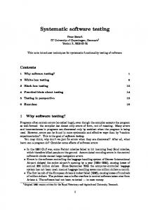
A large part of today’s innovation in the automotive industry is achieved by extending the functionality of vehicle software [13]. The software’s increase in scope and the increase in complexity connected with it, call for new ways of dealing with the development and the testing of embedded software. On the development side, these challenges have been met, since the mid 1990s, by a paradigm shift in the automotive software development. This leads to the traditional, document-based software development in the vehicle subsystems engine / powertrain, chassis and body / comfort being increasingly displaced by a model-based development [2,15,16,10,17]. traditional software development
requirements
specification
design
implementation testing
model-based software development
requirements
modelling testing
Figure 1. Traditional vs. model-based software development
Analogous to traditional development, the model-based development process starts with a requirements phase, in which the requirements of the functionality to be realized are being specified textually by using tools such as DOORS [7]. Following that, this innovative development approach is characterized by the integrated deployment of executable models for specification, design and implementation, using commercial modeling and simulation environments such as Matlab / Simulink / Stateflow [12] or ASCET-SD [1]. These tools use block diagrams and extended state machines as modeling notations. Very early in this development procedure an executable model of the control software (functional model) is developed, which can be simulated as well as tested. This executable model is used throughout the downstream development process and forms the ’blueprint’ for the automatic or manual coding of the embedded software. In practice, this development is reflected in an evolution of the functional model from an early logical model to an implementation model and its transformation into C code (model evolution). As compared to traditional software development, where phases are clearly separate, modelbased development shows the phases specification, design and implementation 1 The work described was partially performed as part of the IMMOS project funded by the German Federal Ministry of Education and Research, Project Ref. 01ISC31D. 2 Email: mirko.conrad | ines
[email protected] 3 Email:
[email protected]
M. Conrad et al. / Electronic Notes in Theoretical Computer Science 111 (2005) 13–26
15
to have grown together much more strongly (Figure 1). The seamless utilization of models facilitates a highly consistent and efficient development. Also within the framework of model-based development it is essential to subject the software being developed to an appropriate combination of verification and validation measures in order to detect errors and produce confidence in the correct functioning of the software. In the industrial field, dynamic testing forms the focal point of analytical quality assurance. Since the executable model could be exploited as an additional, comprehensive source of information for testing, new possibilities and synergy potentials for the test process arise in the context of model-based development. Considering the question of efficiency, one should make the most of these possibilities. In the automotive industry, such a test process, being closely connected with the model-based development, including a combination of different test methods which complement each other, and thereby utilizing the executable model as a rich source of information for the test, is called a model-based test. So, the automotive view on model-based testing (cf. [8]) is a rather process-oriented one [11,14]. In particular, no additional models are being created for test purposes, but the functional models already existent within the model-based development are used for the test. Satisfactory solutions for model-based testing are slow in arriving. With regard to the systematic design of test scenarios especially, there is a lot of room for improvement. In order to enable a systematic model-based test, a test design from different perspectives, and with a subsequent consistency check is presented in this paper. The following description of the model-based black-box testing (MB 3 T ) approach explicates this basic concept.
2
Model-based Black-box Testing
In order to define tests capable of detecting errors and producing confidence in the software, test scenarios should be designed which are systematically based on the software requirements. In the case of the test scenarios being directed only towards the technical realization of the test object, there would be the danger of neglecting and not adequately testing the original requirements made on the test object. However, requirement-based, i.e. logical, test scenarios are abstract and not executable. This means that they cannot be used directly for test execution. Therefore, additional executable test scenarios are needed, which can stimulate the interface of the respective test object. Finally, it should be checked, whether or not the logical test scenarios are fully covered by the executable ones. These demands led us to define the model-based black-box testing approach, which has recently been successfully
16
M. Conrad et al. / Electronic Notes in Theoretical Computer Science 111 (2005) 13–26
employed in a number of automotive embedded software development projects at DaimlerChrysler. The MB 3 T approach makes it possible to define test scenarios for software developed in a model-based way from two different perspectives and to create consistency between both (Figure 2): •
Requirement-based test design: Early in development, logical test scenarios are defined, based on the textual requirements specification of the embedded software. The requirement-based test scenarios created in this way are specified at a high level of abstraction and do not contain any implementation details for the test object. Due to their close link to the requirements it is easy to check which requirements are covered by which test.
•
Model-based test design: Once the functional model is available, executable test scenarios are derived from it with the help of the classification-tree method for embedded systems [4,5,11]. These are tailored to the functional model’s interface, or rather, the software derived from it, and therefore also lend themselves to test execution.
•
Consistency check: By means of a set of checking rules, the consistency between logical, requirement-based and executable model-based test scenarios can be checked and thus guaranteed.
The three above-mentioned steps will be described in more detail in the following sections and illustrated using a chassis system [3] as an example. consistency check
requirement-based test design
model-based test design
test object Figure 2. M B 3 T Testing automotive software from two different perspectives
2.1 Requirement-based Test Design In the automotive field, requirements on embedded software are usually described textually. Example 2.1 For an antilock braking system (ABS) a high-level requirement (HLR) of this kind could read as follows:
17
M. Conrad et al. / Electronic Notes in Theoretical Computer Science 111 (2005) 13–26 •
HLR-1: The ABS system should guarantee near-optimum braking performance, irrespective of vehicle speed when braking.
•
HLR-1.1: The ABS system should control the vehicle speed in the interval between vmin= 2 km/h and vmax= 250km/h.
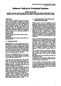
For the design of requirement-based tests we utilize the classification-tree method (CTM) [9]. According to this black-box testing method, the input domain of a test object is analyzed on the basis of its functional specification with respect to various aspects regarded as relevant for the test. For each aspect, disjoint and complete classifications are formed. Classes resulting from these classifications may be further classified iteratively. The stepwise partition of the input domain by means of classifications is represented graphically as a tree. Subsequently, test scenarios are formed by combining classes of different classifications. This is done by using the tree as the head of a combination table in which test scenarios are specified. ABS
environment
classification
ground
dry
class
road
ice
wet
snow
straight
curved
driver
vehicle dynamics
brake
speed
not activated
strong braking
weak braking
_ v > Vmax
v < Vmin low
high
middle
1: Strong braking on ice 2: Braking on wet road 3: Braking on a curve
Figure 3. Requirement-based classification-tree with logical test scenarios for ABS
Example 2.2 HLR-1 suggests considering different speeds at the moment of braking, while HLR-1.1 restricts the speed interval to be considered. Consequently, the vehicle speed is a significant test aspect. Further, HLR-1 requires a near-optimum braking performance to be achieved by the ABS system (expected test object behavior). Therefore, one also has to regard aspects impacting the braking behavior of the vehicle. These are the brake pressure initiated by the driver, the ground friction and the kind of road (straight or curved). All the test aspects mentioned are illustrated by the classification-tree in Figure 3. Due to the abstractness and understandability of tests on this level we specify the classifications in a qualitative way, e.g. we use ’low’, ’middle’ and ’high’ to describe the speed classes, rather than specific values or value intervals. Note that the both classes ’v < vmin ’ and ’v > vmax ’ have been specified in order to have a complete classification for speed. They are not used in the test scenarios for HLR-1 (they may be used for testing a different requirement, for instance).
18
M. Conrad et al. / Electronic Notes in Theoretical Computer Science 111 (2005) 13–26
The maximum number of test scenarios which could be formed from a classification-tree is the number of combinations of leaf classes. Since this number is generally too high (in the case of the classification-tree in Figure 3 this number is 120), a strategy for selecting a subset of whole possible tests is necessary. Such a strategy is related to the question of test depth determination. The determination of test depth depends on the criticality of the test object, the project guidelines, the testing standards to be met and, last but not least, the decision of the testing engineer. For our example we require to cover all the classes of the main test aspect, i.e. vehicle speed. Consequently, as shown in Figure 3, three test scenarios are selected, each of them covering a relevant speed class.
env_curve env_mue vehicle_steeringAngle abs_brakePressure vehicle_accPedal vehice_brakePedal vehicle_gear
vehicle_with_abs
vehicle_with_abs Inputs
env_curve
0
]0.02,inf[
]0,0.02]
env_mue
]0,0.1]
vehicle_steeringAngle
]0.6,1]
]0.1,0.3] ]0.3,0.6]
[-540,-180[
]180,540]
[-180,0] ]0,180]
vehicle_accelerator
0
1
]0,0.5] ]0.5,1[
vehicle_brake
0
vehicle_gear
1
-1
]0,0.5] ]0.5,1[
0
5
0
4
1
3
2
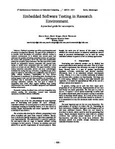
Figure 4. Model interface and model-based classification-tree of ABS system
The insights obtained during the requirement-based test design serve as the starting point for model-based testing. The classifications of the requirementbased tree determine the test aspects which have to be interpreted as model inputs. The classes indicate how the domains of the inputs considered should be partitioned. Requirement-based test scenarios describe the situations which are to be covered by model-based test scenarios.
M. Conrad et al. / Electronic Notes in Theoretical Computer Science 111 (2005) 13–26
19
2.2 Model-based Test Design Model-based test design is performed using an extended version of the classification-tree method, namely classification-tree method for embedded software (CTM/ES) [4,6,11]. The CTM/ES is a model-oriented black-box test design technique which allows a comprehensive graphical description of timedependent test scenarios by means of abstract signal waveforms that are defined stepwise for each model input. The classifications of the model-based tree are the input variables of the functional model under test (Figure 4).
Example 2.3 Figure 4 shows the interface of the functional Simulink model as well as the model-based classification-tree for the antilock braking system ABS. The functional model’s input signals constitute the test aspects for the model-based test design. In contrast to the requirement-based classificationtree (Figure 3) the classifications on this level are specified using specific values or intervals of values. Figure 5 shows the model-based test scenarios for ABS. The three test scenarios specified in the combination table correspond to the logical test scenarios in Figure 3. Each test scenario consists of a number of steps, while each step is associated with a time stamp. Changing the values of a model input along the test steps is shown by marking different classes of the classification corresponding to that input. Continuous changes are defined by transitions (connecting lines) between marks in subsequent steps.
Its classes are obtained by dividing the range of each variable into a set of complete and non-overlapping intervals. Furthermore, the test scenarios describe the course of these inputs over time (Figure 5). Later in the testing process, the resulting graphical test descriptions are automatically transformed into sequences of input values over time. These sequences can be deployed in different test environments, namely in modelin-the-loop (MiL), software-in-the-loop (SiL) and hardware-in-the-loop (HiL), in order to test different evolution stages of the test object. Of course, the test scenarios must be customized to the interfaces of the different test environments. This is, however, a straightforward task. In this way, the model is used as a comprehensive source of information for the definition of tests in all test phases.
20
M. Conrad et al. / Electronic Notes in Theoretical Computer Science 111 (2005) 13–26 vehicle_with_abs Inputs
env_curve
0
]0.02,inf[
]0,0.02]
env_mue
]0,0.1] ]0.1,0.3]
vehicle_steeringAngle
]0.6,1]
]0.3,0.6]
[-540,-180[ [-180,0]
]180,540]
]0,180]
0
vehicle_accelerator
0
1
]0,0.5]
]0.5,1[
vehicle_brake
0
vehicle_gear
1
]0,0.5]
]0.5,1[
-1
5 0
4
1
3
2 1: Strong braking on ice 1.1: start 1.2: driving away 1.3: accelerating 1.4: braking 1.5: end 2: Braking on wet road 2.1: start 2.2: driving away 2.3: accelerating 2.4: braking 2.5: no braking 2.6: braking 2.7: end 3: Braking on a curve 3.1: start 3.2: driving away 3.3: accelerating 3.4: steering 3.5: braking 3.6: steering 3.7: strong braking 3.8: end
Time [sec] 0 0.1 3 5 10 Time [sec] 0 0.1 3 5 7 8 10 Time [sec] 0 0.1 3 5 7 10 12 13
Figure 5. Model-based classification-tree and test scenarios for ABS system
2.3 Consistency Check between Requirement-based and Model-based Tests
MB 3 T also provides the test engineer with a set of checking rules which make it possible to examine the consistency between the abstract, requirementbased tests and the implementation-oriented, model-based tests, defined in different phases of the development process [3]. The consistency checks in their entirety ensure the necessary degree of thoroughness and completeness for the model-based testing process. These checking rules comprise checks on the classification-trees as well as on the test scenarios (Figure 6). In detail, the consistency check is to be carried out in the following stages: (i) Compare both classification-trees. (ii) Analyze whether the requirement-based test scenarios are covered by the model-based test scenarios.
21
M. Conrad et al. / Electronic Notes in Theoretical Computer Science 111 (2005) 13–26
model- based test scenarios
vehicle_with_abs Inputs
requirement-based test scenarios
env_curve
0 ]0.02,inf[ ]0,0.02]
env_mue
]0,0.1] ]0.1,0.3]
]0.6,1] ]0.3,0.6]
vehicle_steeringAngle
[-540,-180[ ]180,540] [-180,0] ]0,180] 0
vehicle_accelerator
0
1
]0,0.5]
]0.5,1[
vehicle_brake
0 ]0,0.5]
vehicle_gear vehicle_gear 11
]0.5,1[
-1 -1
55
00
44
11
33
22
ABS
environment
ground
dry
road
ice
wet
snow
driver
straight
vehicle dynamics
brake
curve
not strong activated braking weak braking
speed
v < Vmin
v > Vmax
low
high middle
1: Strong braking on ice 2: Braking on wet road 3: Braking on a curve
1: Strong braking on ice 1.1: start 1.2: driving away 1.3: accelerating 1.4: braking 1.5: end 2: Braking on wet road 2.1: start 2.2: driving away 2.3: accelerating 2.4: braking 2.5: no braking 2.6: braking 2.7: end 3: Braking on a curve 3.1: start 3.2: driving away 3.3: accelerating 3.4: steering 3.5: braking 3.6: steering
Time [sec] [sec] Time 00 0.1 0.1 33 55 10 10 Time [sec] 00 0.1 0.1 33 55 77 88 10 10 Time [sec] [sec] Time 00 0.1 0.1 33 55 77 10 10 12 12 13 13
consistency check
3.8: end
relations relationsbetween betweenclasses classes relations relationsbetweenclassifications betweenclassifications ground ground brake brake ........... ........... .......... ..........
env_mue env_mue vehicle_brake vehicle_brake .......... .......... .......... ..........
1:1 1:1 1:1 1:1 .... .... ......
Figure 6. Consistency check between requirement-based and model-based test scenarios
2.3.1 Comparison of Classification-Trees The first stage of the consistency check is the comparison of the requirementbased classification-tree (R-CT) with the model-based classification-tree (MCT). The first step here is to assign the R-CT classifications (i.e. requirement aspects regarded as relevant to the test) to the respective M-CT classifications (i.e. model inputs). These have to be in a 1:1 or 1:n relation to each other. If there is no valid relation for an R-CT classification to the M-CT classifications, this signifies that the test aspect corresponding to the model input represented by that classification was not considered when the R-CT was generated or that it is not relevant to the test after all. In the case of irrelevance, such model inputs may be set to default constant values. At the second step in the comparison of the classification-trees, the classes of the related classifications are compared. The possible relations between classes within a 1:1 classification relation are 1:1, 1:n, n:1 and m:n. The relation between classes within a 1:n classification relation is a bit more complex: For an R-CT class the following cases for the related M-CT classes are possible: - one class from each n related classification, - a set of classes from each n related classification. Example 2.4 As examples of 1:1 relations between classifications the relation between ’ground’ in the R-CT and ’env mue’ in the M-CT as well as the relation between ’road’ in the R-CT and ’env curve’ in the M-CT of the ABS system can be mentioned (see Figure 3 and Figure 4). The above-mentioned
22
M. Conrad et al. / Electronic Notes in Theoretical Computer Science 111 (2005) 13–26
classifications represent the road friction and road curve in two different abstraction levels respectively. Figure 7 illustrates these classification relations and the corresponding 1:1 and 1:n relations between their classes.
R-CT
ground
M-CT 1:1 relation
1:1 relation
snow
R-CT
M-CT 1:1 relation
env_mue
]0.1,0.3]
env_curve
road
curved
1:n relation
]0,0.02] ]0.02,inf[
Figure 7. 1:1 classification relation as well as 1:1 and 1:n class relations between R-CT and M-CT
Example 2.5 An example of a 1:n relation between classifications in both trees of the ABS system is the relation between ’speed’ in the R-CT and the classifications ’vehicle accelerator”, ’vehicle-brake’ and ’vehicle gear’ in the MCT, since the vehicle speed is determined by the combination of values of the inputs mentioned. Of course in a more complex environment model further aspects such as the road slope or the wind speed would also play a role in determining the vehicle speed and should be considered while defining the MCT classifications related to ’speed”. Figure 8 illustrates the above-mentioned classification relation and the relation between the ’high’ speed class and the possible sets of the corresponding classes of the ’vehicle accelerator”, ’vehiclebrake’ and ’vehicle gear’ classifications. The depicted class relation makes it possible to, for example, relate the combination of the values •
vehicle accelerator from the interval ]0.5, 1[
•
vehicle brake = 0
•
vehicle gear = 4
to the high speed. Note that this relation indicates the possibility of reaching a high speed if the corresponding classes have been marked in the M-CT (necessary condition). The question of whether the high speed is actually reached, depends on the dynamic aspect of the test scenario, i.e. the initial test step and the duration of the test step or test steps running with the above values (sufficient condition).
M. Conrad et al. / Electronic Notes in Theoretical Computer Science 111 (2005) 13–26
R-CT
23
M-CT 1:n relation
speed
vehicle_accelerator vehicle_brake
high
vehicle_gear
]0.5,1[ 1 0
]0,0.5] 3 4 5
Figure 8. 1:n classification relation between R-CT and M-CT
2.3.2 Comparison of Test Scenarios The second stage of the consistency check is the comparison of the requirementbased test scenarios with the model-based test scenarios. An R-CT test scenario is covered by an M-CT test scenario, if the combination coverage criteria for mapping of R-CT test scenarios onto M-CT test scenarios, as shown in Table 1, are met. The combination coverage criteria have to be checked for all classes marked in the R-CT test scenario. As examples for combination coverage criteria consider the following cases of the R-CT and M-CT of the ABS system, shown in Figures 3 and Figure 5. Example 2.6 ’ground’ in the R-CT and ’env mue’ in the M-CT are 1:1 related classifications. The classes of these classifications, ’snow’ and ]0.1, 0.3], are also 1:1 related. According to the first row of Table 1 the use of ]0.1, 0.3] in the test steps of the third M-CT test scenario (Braking on a curve) fulfills the coverage criterion concerning the class ’snow’. ’road’ in the R-CT and ’env curve’ in the M-CT are 1:1 related classifications. The classes of these classifications, ’curved’ and ]0, 0.02], ]0.02, inf [, are 1:n related. According to the second row of Table 1 the use of ]0, 0.02] in two test steps of the third M-CT test scenario (Braking on a curve) fulfills the coverage criterion concerning the class ’curve’. ”speed’ in the R-CT and {”vehicle accelerator’ , ’vehicle brake’ , ’vehicle gear”} in the M-CT are 1:n related classifications. Figure 8 shows a relation between the class ”high’ and the corresponding sets of classes of the M-CT. According
24
M. Conrad et al. / Electronic Notes in Theoretical Computer Science 111 (2005) 13–26
relation between classification
relation between classes (a and ai ’s are classes of RCT, b and bi ’s classes of M-CT)
combination coverage criteria
1:1 relation
1:1 relation a↔b
Class b is used in at least one test step of a test scenario.
1:n relation a ↔ b1 + · · · + bn
One of the classes b1 , · · · , bn is used in at least one test step of a test scenario.
n:1 relation a1 + · · · + an ↔ b
Class b is used in at least one test step of a test scenario.
m:n relation a1 + · · · + an ↔ b1 + · · · + bn
One of the classes b1 , · · · , bn is used in at least one test step of a test scenario.
1:n relation
one class from each n related The combination of classes classifications b1 , · · · , bn is used in a1 + · · · + an ↔ b1 + · · · + bn at least one test step of a test scenario. a set of classes from each n related classifications a ↔ (b11 + · · · + b1n )× (bk1 + · · · + bkn
A combination of classes b1i , · · · , bkj is used in at least one test step of a test scenario.
Table 1. Combination coverage criteria for mapping of R-CT test scenarios onto M-CT test scenarios
to the last row of Table 1 the use of 1 for ’vehicle accelerator’ , 0 for ’vehicle brake’ and 4 for ’vehicle gear’ in the third step of the first M-CT test scenario (Strong braking on ice) fulfills the coverage criterion concerning the class ’high”. Accomplishing the combination coverage check, as shown in the above three examples, for all classes marked in the R-CT test scenarios shall provide the guarantee for the consistency between the M-CT and R-CT test scenarios of the ABS system.
3
Summary
MB 3 T enhances the model-based development of embedded automotive software with a systematic approach for deriving tests from two different per-
M. Conrad et al. / Electronic Notes in Theoretical Computer Science 111 (2005) 13–26
25
spectives. By using the executable model as a rich source of information for the testing process, the MB 3 T approach provides a solution, which has been proven in practice, to the challenges of model-based testing in the automotive industry. Requirement-based test design with the aid of the classification-tree method makes it possible to systematically create logical test scenarios early in the development process and also assures the requirements coverage necessary. As a rule, this normally results in flexible m:n relations between the requirements and the logical test scenarios thus created. This represents an improvement in comparison to the rigid 1:1 relation which is currently much in use. Model-based test design with the classification-tree method for embedded systems guarantees the systematic derivation of time-variant test scenarios for the executable artifacts of model-based development (e.g. the logical model, implementation model, C code). As this method is based on the data-oriented partitioning of the input domain into equivalence classes, the data range coverage of the test scenarios can easily be achieved. A methodology for analyzing the relations between requirement-based and model-based test scenarios, building on the graphical means of description used by the classification-tree method, reduces the gap between these test scenarios. It is much easier to understand which requirements are covered by which executable tests by using the intermediate stage of requirement-based tests. The comparatively higher effort, resulting from the tests being designed from two different angles, leads to a better and more systematic way of generating tests which, in turn, ensure a test coverage with regard to two complementary coverage criteria. Thus, the MB 3 T approach should be employed especially in the case of software developed in a model-based way which has high safety and reliability requirements.
References [1] ASCET-SD, ETAS GmbH, de.etasgroup.com/products/ascet sd/. [2] Broy, M., “Automotive Software Engineering. Proc. 25th Intl. Conference on Software Engineering”, (ICSE 03), 2003, Portland, Oregon, pp. 719-720 [3] Burckhardt, M., “Fahrwerktechnik - Radschlupfregelsysteme”, Vogel Verlag, W¨ urzburg, Germany, 1993 [4] Conrad, M., D¨ orr, H., Fey, I., Yap, A., “Model-based Generation and Structured Representation of Test Scenarios”, Workshop on Software-Embedded Systems Testing (WSEST), Gaithersburg, USA, Nov. 1999. [5] Conrad, M., Pohlheim, H., Fey, I., Sadeghipour, S., “Modell-basierter Black-box-Test f¨ ur Fahrfunktionen”, Techn. Report RIC/S-2002-001, DaimlerChrysler AG, Research Information and Communication, Berlin, 2002
26
M. Conrad et al. / Electronic Notes in Theoretical Computer Science 111 (2005) 13–26
[6] Conrad, M., Sax, E.: Mixed Signals. In: B. Broekman, E. Notenboom: “Testing Embedded Software”, Addison-Wesley, 2002 [7] DOORS, Telelogic AB, www.telelogic.com/products/doorsers. [8] El-Far, I. K., Whittaker, J. A., “Model-based Software Testing,” In: Marciniak, J. J. (Ed): “Encyclopedia of Software Engineering”, 2nd edition, Wiley 2001 [9] Grochtmann, M., Grimm, K., “Classification Trees for Partition Testing”, Software Testing, Verification and Reliability, vol. 3, pp. 63-82, 1993. [10] Klein, T., Conrad, M., Fey, I., Grochtmann, M., “Modellbasierte Entwicklung eingebetteter Fahrzeugsoftware bei DaimlerChrysler”, Modellierung 2004, Marburg, Germany, March 2004 [11] Lamberg, K., Beine, M., Eschmann, M., Otterbach, R., Conrad, M., Fey, I., “Model-based testing of embedded automotive software using MTest”, SAE World Congress 2004, Detroit, Michigan, Mar. 2004 [12] Matlab/Simulink/Stateflow, The MathWorks Inc., http://www.mathworks.com [13] Mutz, M.,Harms, M., Horstmann, M., Huhn, M., Bikker, G., Kr¨omke, C., Lange, K., Goltz, U., Schnieder, E., Varchmin, J.-U., “Ein durchgehender elektronischer Entwicklungsprozess f¨ ur elektronische Systeme im Automobil”, VDI Berichte Vol. 1789, pp.43-75, VDI-Verlag, D¨ usseldorf, Germany, 2003 [14] Pretschner, A., Philipps, J., “Szenarien modellbasierten Testens”, Techn. Report TUM-I0205, Technische Universit¨ at M¨ unchen, Institut fr Informatik, July 2002. [15] Rau, A., “Model-Based Development of Embedded Automotive Control Systems”, PhD Thesis. Dept. of Computer Science, University of T¨ ubingen, Germany, 2002. [16] Sax, E., M¨ uller-Glaser, K.-D., “A seamless, model-based Design Flow for Embedded Systems in Automotive Applications”, 1st Intl Symposium on Automotive Control, Shanghai, China, 2001 [17] Sch¨ auffele,J., Zurawka,T. “Automotive Software Engineering”, Vieweg Verlag, Wiesbaden, Germany, 2003