Ahmad Samihâ â¡, Ren WangÎ¥, Anil Krishnaâ, Christian MacioccoÎ¥, Charlie TaiÎ¥ and Yan Solihinâ¡. â Intel Architecture Group. Intel Corp. Austin, TX, USA.
Energy-Efficient Interconnect via Router Parking
∗
Ahmad Samih†‡ , Ren WangΥ , Anil Krishna∓ , Christian MacioccoΥ , Charlie TaiΥ and Yan Solihin‡ ∓ Υ CPU Research Intel Labs Intel Architecture Group Qualcomm Inc. Hillsboro, OR, USA Intel Corp. Raleigh, NC, USA {ren.wang, christian.maciocco, Austin, TX, USA {krishnaa}@qti.qualcomm.com charlie.tai}@intel.com {ahmad.a.samih}@intel.com †
‡
North Carolina State University Raleigh, NC, USA {solihin}@ncsu.edu
Abstract
tal chip power if 50% of the cores are utilized since it will continue to operate at maximum frequency to serve the active cores).
The increase in on-chip core counts in Chip MultiProcessors (CMPs) has led to the adoption of interconnects such as Mesh and Torus, which consume an increasing fraction of the chip power. Moreover, as technology and voltage continue to scale down, static power consumes a larger fraction of the total power; reducing it is increasingly important for energy proportional computing. Currently, processor designers strive to send under-utilized cores into deep sleep states in order to reduce idling power and improve overall energy efficiency. However, even in state-of-the-art CMP designs, when a core goes to sleep the router attached to it remains active in order to continue packet forwarding. In this paper, we propose Router Parking – selectively power-gating routers attached to parked cores. Router Parking ensures that network connectivity is maintained, and limits the average interconnect latency impact of packet detouring around parked routers. We present two Router Parking algorithms – an aggressive approach to park as many routers as possible, and a conservative approach that parks a limited set of routers in order to keep the impact on latency increase minimal. Further, we propose an adaptive policy to choose between the two algorithms at run-time. We evaluate our algorithms using both synthetic traffic as well as real workloads taken from SPEC CPU2006 and PARSEC 2.1 benchmark suites. Our evaluation results show that Router Parking can achieve significant savings in the total interconnect energy (average of 32%, 40% and 41% for the synthetic, SPEC CPU2006, and PARSEC 2.1 workloads, respectively).
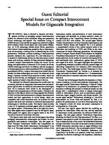
As technology and operating voltages continue to scale down, as evidenced by Intel’s 22nm transistor technology [19] and the near-threshold voltage design [5], static power is becoming a larger component of the total power [2, 9, 36]. Figure 1(a) shows the breakdown of an interconnect router’s dynamic versus static power at 2GHz, with Vdd of 1.1 V and 1.0 V, and under three different process technologies – 65nm, 45nm, and 32nm. The results are obtained from the Orion2.0 [21] power model. As shown in the figure, the static power consumption increases rapidly as technology scales down, going from 11.2% of the total router power in the 65nm (1.1V) technology to 33.6% in the 32nm (1.1V) technology. Further, Figure 1(b) shows the breakdown of the static and dynamic power in the 32nm technology as Vdd decreases from 1.1V to 0.7V. The static power reaches 44.3% of the total power at 0.7V. Finally, the dynamic power numbers shown in these plots are measured based on 50% load activity. According to International Data Corporation (IDC) study [15], servers achieve utilization of only 10% to 15%. With such low average utilization, the share of static power to the total interconnect power is expected to be even larger. 100
Introduction
70
Percentage (%)
Percentage (%)
80
60 50 40 30
∗ This work was done while the first author was a PhD candidate at NC State University. This work is supported in part by NSF grant 0915503.
978-1-4673-5587-2/13/$31.00 ©2013 IEEE
60
40
20
10 0
1.1V
1.0V
65nm
Chip Multi Processors (CMPs) are increasingly becoming the mainstream hardware architectures for a wide range of computing platforms. In such systems, the interconnect fabric consumes an increasing fraction of the chip power [29] in order to support higher bandwidths and larger number of cores. Recent studies show that, if all cores are 100% utilized, the interconnects in Intel’s SCCC, Sun’s Niagara [27], Intel’s 80-core chip [16], and MIT’s RAW chip [23] consume 10%, 17%, 28% and 36% of the total chip power, respectively. With lower core utilization, the fraction of the power consumed by the interconnect is much higher (e.g., in Intel’s SCCC, interconnect power contribution jumps from 10% to 17% of the to-
Static Power Dynamic Power
80
20
1
100
Static Power Dynamic Power
90
1.1V
1.0V
45nm
(a)
1.1V
1.0V
32nm
0
1.1V 1.0V 0.9V 0.8V 0.7V
(b)
Figure 1. Static router power vs. dynamic router power for various technologies, and operating voltages. Dynamic router power is measured at 50% load.
ITRS [20] projects that by 2022, a single chip may include more than 100 cores. The rising number of cores on a single chip, accompanied by limited power envelops and low system utilization create increasing opportunities to send many of these cores to deep sleep states. Unfortunately, even after exploiting these opportunities, the system would not be energy proportional [3] if the idling power is high. With current interconnects, even when an idle core does not generate any interconnect traffic, the router and links attached to it remain active in order to maintain full interconnect operation.
Prior studies [36, 14] attempted to reduce the interconnect power by reactively power gating router components (e.g. links, ports, or buffers) in response to traffic load. With such an approach, performance may be penalized significantly if the wake-up latency is high or traffic is unpredictable. Hence, only lightweight power saving techniques can be employed. Furthermore, the approach cannot take a full advantage of situations in which a large number of cores are in deep sleep and their associated routers are idle and can be fully power gated without impacting latency by much. To this end, and as our first contribution, we propose Router Parking (RP), a novel interconnect power management approach that aims to reduce the static interconnect power. The main idea behind our proposal is to power gate a subset of routers associated with sleeping cores by proactively aggregating traffic to the active routers such that it conserves power, does not impact function, and minimizes the impact on performance. Without proactive aggregation, traffic disperses across all routers even in low traffic scenarios. This can keep routers lightly loaded but active – even when their associated cores are parked. Under various topologies, such as Mesh or Torus, there usually exist multiple paths from a given source to a given destination router. Therefore, keeping all routers associated with parked cores active may not be necessary. Parking routers associated with sleeping cores must not cause interconnect partitions, where a given pair of active cores are not able to reach each other. Even after ensuring that no interconnect partitions are created, there are power and performance trade-offs in RP. The static power savings enabled by parking more routers must be balanced against the increase in interconnect latency due to rerouting around parked routers, which in turn increases run-time and energy. In order to address this trade-off, and as a second contribution, we propose and evaluate various RP algorithms. On one end of the solution space is an Aggressive Router Parking (RP-A) approach that strives to park as many routers as possible in order to maximize static power savings. This solution, under heavy traffic, may have an undesirable end-to-end latency impact due to excessive packet detours. The other end of the solution space is a Conservative Router Parking (RP-C) approach that parks fewer, carefully selected, routers in order to minimize the impact of RP on interconnect latency. Motivated by encouraging experimental results on both ends of the spectrum, we design an Adaptive Router Parking (RP-Adp) approach that monitors the interconnect utilization and chooses between RP-A and RP-C at run time, enabling power savings while limiting performance impact. We evaluate RP on a 64-core tiled CMP using Simics 4.7 [25] with a cycle-accurate interconnect simulator based on the Garnet [11] interconnect model and the Orion2.0 [21] power model. We experiment with both synthetic traffic and real workloads taken from the SPEC CPU2006[37] and PARSEC 2.1[4] benchmark suites. Our evaluations show that for SPEC CPU2006 and PARSEC 2.1 workloads, RP can reduce the total interconnect energy by an average of 41% and 40%, respectively. Finally, for these two workload suites, the performance metric, Weighted Speedup, is reduced by less than 0.2% and 0.4% on average, and 3% and 4% in the worst case, respectively.
2
Related Work
There is a rich body of work that has studied the problem of reducing interconnect traffic in CMPs. We divide this work into the following main categories. Reducing Static Power Consumption. Soteriou et al. [36] proposed a component-based router power gating technique that works by monitoring the interconnect link utilization and power gating components such as ports and links in response to bursts and dips in network traffic. Although this approach shows promising result, it has several drawbacks. First, performance may suffer significantly when the wake-up latency is high or traffic is unpredictable. In order to react to changes in traffic quickly, only lightweight power saving techniques can be employed. For example, it power gates only certain router components, hence missing an opportunity to power gate entire routers. Second, the approach is agnostic to the core sleep state. It misses an opportunity for power gating mostly idle routers attached to sleeping cores. Finally, in addition to the previous issues, this approach assumes that outbound and inbound links have different physical ports for the convenience of maintaining network connectivity. Whereas many modern interconnects such as Intel’s LightPeak [18] have their inbound and outbound links connected to the same physical port, and are hence either both on or both off. To the best of our knowledge, Router Parking is the first work that takes a holistic view of the system by parking selective routers based on the sleep state of their associated cores. By doing this proactively, traffic is aggregated away from sleeping routers, hence we avoid the need for a fast wake-up latency. At the same time, power gating entire routers enable saving more power. However, component-based power-gating may complement Router Parking (RP) if it is applied to active routers. Reducing Dynamic Power Consumption. Matsutani et al. [26] proposed decreasing router operating frequency and supply voltage in order to reduce the router power when necessary. Link Dynamic Voltage Scaling [34] explored scaling link frequency and voltage to reduce link power consumption under low utilization. Dynamic Voltage and Frequency Scaling (DVFS) is also exploited [28] to tune the frequency of on-chip routers to improve power and performance. These approaches mainly aim at reducing the dynamic power consumed by active routers and links while our work reduces static power. This body of work is orthogonal to our Router Parking techniques and can be applied to further reduce power of the remaining active routers. Reducing Dynamic and Static Power Consumption. Researchers have also proposed techniques to save both dynamic and static interconnect power [30, 14, 22]. Bufferless routers [30], observes that buffers consume a significant fraction of the total router power consumption, and therefore bufferless routing schemes can reduce power. These works all focus on power managing router components by reacting to the traffic pattern. In contrast, we take a holistic approach to adaptively and proactively manage the traffic and enable the entire router to enter low power state. Researchers also proposed more sophisticated topologies, e.g., Parallel Concreted Mesh (PC-Mesh) [7] and Homogeneous Parallel Concentrated Mesh (HPC-Mesh) [6] that enable richer connections thus providing more opportunities for power saving and fault tolerance. How is Router Parking different from Fault Tolerant Networks. There has been substantial research on Fault Tolerant Networks (FTN) [1, 38, 13]. While one may imagine applying FTN
techniques to route around parked routers, there are fundamental differences between FTN and our router parking. In RP, a centralized manager is preferred because it provides an ability to perform holistic power management. In contrast, FTN does not manage power and prefers distributed algorithms to tolerate unpredictable failures. The need for holistic power management is recognized by the industry and is incorporated into various products [17], and other NoC studies [31]. Another difference is that RP operation must be fast in order to accommodate frequent interconnect changes, while faults in FTN are rare cases. Hence, there is no need for FTN algorithms to be fast. Finally, RP must ensure full network connectivity, whereas in FTNs, faulty routers may cause disconnected network partitions.
3
Router Parking Design
At a high level, router parking is applied to a system that consists of n tiles interconnected together via an interconnect fabric with a topology such as a Mesh 1 or a Torus. Router Parking is managed by a centralized Fabric Manager (FM) that is responsible for configuring, monitoring and re-configuring the interconnect. A centralized FM is essential for efficient and effective interconnect power management as seen in many recent products, e.g., Intel Sandy Bridge architecture employs a centralized System Agent to handle power management [17]. Further, changes in the interconnect configuration warrant changes in the routing tables of individual routers. This requires globally consistent view of the active network to be visible to all nodes. While this could be achieved via a distributed approach, it increases the operational complexity and reconfiguration latency as pointed out by Aisopos et al. [1]. The FM could be either added as a functionality in firmware to one of the tile’s LLC cache controllers, or to one of the on-chip memory controllers. It could also be implemented as a dedicated engine located in the fabric, similar to Intel’s optical fabric (LightPeak) FM [18] which holds several fabric management responsibilities, such as, setting up source-to-destination channels and handling topology changes. Further, the code of the FM could be executed on one of the cores in the system. In this work, we employ and evaluate an on-chip dedicated engine for the FM and install it in a tile positioned in the middle of the Mesh network. This ensures that the average distance to other nodes in the network is minimized. Epochs Reconfiguration is attempted after periodic intervals called epochs. The epoch length is chosen such that epoch length < core exit latency − For example, if interconnect reconf iguration latency. the core exit latency from deep sleep state is 80µs and the latency of doing a full interconnect reconfiguration is 15µs, then the epoch length should be < 65µs. This ensures that in the worst case, if a core gets interrupted immediately after reconfiguration completes, by the time it exits sleep, the interconnect has been reconfigured and its router is up and ready to service its core. At the end of each epoch, the FM follows a sequence of actions to prepare for a potential network reconfiguration. Gathering node information. At the end of each epoch, the FM performs a multi-cast to all active routers asking for the status of their associated nodes. Parked routers are guaranteed to have 1 In this work we implement and evaluate our algorithms on a 2D-Mesh topology; the RP approach can, however, be applied to other interconnects with minimal modifications.
their associated nodes parked as well, and need not be involved in this process. Nodes with active routers reply to the FM’s broadcast with information about their status (parked or active). There are three ways for parked nodes to supply their status to the FM without themselves waking up. First, a small logic in the node is responsible for communicating with the FM using the available communication links; therefore, there is no need to wake up the whole computing node to reply to the FM’s query. Second, the router detects node inactivity by a timeout method and replies on behalf of the node. Third, the node notifies the FM before it goes to sleep; the FM, in turn, saves this information for future use. Processing gathered information. Once the FM receives the node status information, it processes the information to measure connectivity and decide which routers should be parked during the next epoch. Once the FM measures connectivity, it computes routing tables for active routers using shortest path routing 2 . The FM uses the following objectives while generating a new network configuration. First, the new configuration should not partition the network. This requirement might be relaxed for special situations – for example, several functional partitions may not need to communicate with each other due to job independence. Second, the algorithm should be able to park as many routers as possible in order to achieve the highest static energy savings. Third, the algorithm should minimize the latency impact due to the necessary detours around parked routers introduced by RP. Finally, the algorithm should be fast. Section 4 describes the algorithms we evaluate in detail. Populating new configuration. All nodes continue to follow the old network configuration and routing decisions until they receive a new configuration from the FM. Once the FM creates the bitmap corresponding to the new configuration, it sends it to all involved nodes in the system. If a given router finds that it is permitted to park, it will power gate its ports, crossbar, and arbiters. Note to ensure packet deliverability, the router may need to wait until it flushes out all packets first. If on the other hand, a given router finds that it remains active, it updates its routing table to reflect the new network configuration. Recall that the interconnect does not freeze when a transition occurs from one epoch to the next. Some routers may be operating under the old routing configuration, while others may be operating under the new routing configuration. The combination may cause undeliverable packets and deadlocks. We discuss how to handle these corner cases in Section 5.2.
4
Router Parking Algorithms
In this section, we describe two basic RP algorithms - Aggressive Router Parking and Conservative Router Parking. We then describe an Adaptive Router Parking algorithm that chooses between the two basic algorithms according to run time interconnect condition.
4.1
Aggressive Router Parking Algorithm
The goal of an Aggressive Router Parking (RP-A) algorithm is to park as many routers as possible while maintaining the network connectivity. However, it may lead to an increased packet delivery latency when packets have to travel more hops to avoid parked routers. Fortunately, there usually exists multiple minimum paths 2 Another possibility is to share the connectivity information with individual cores and let them compute their RTs.
from a given source node to a given destination. Hence, the increase in latency may not be noticeable. However, if the increase in latency is relatively large, this may increase the dynamic router energy which may offset the static energy saving from router parking. Thus, this approach is likely attractive when the interconnect packet injection rate is low because only few packets are affected and it is unlikely for them to impact performance. With a low injection rate, static energy saving may significantly exceed the additional dynamic energy consumption, making it worthwhile. Fortunately, many applications incur a low packet injection rate. For example, our analysis shows that for SPEC CPU2006 applications running on a tiled-CMP with private 32KB L1 and 1MB L2 caches, the average packet injection rate of L2 misses onto the interconnect fabric is typically low: 9 misses per 1000 instructions on average, with a maximum of 45 misses per 1000 instructions. Under this approach, the FM views the interconnected routers as a graph; G(V,E), where routers are depicted as vertices V, connected to each other via bidirectional edges E. The FM processes the graph and evaluates its connectivity. We borrow Tarjan’s Strongly Connected Components [32] algorithm from graph theory for this step. Tarjan’s algorithm calculates the number of strongly connected components in a Graph(V,E) with a linear complexity of O(n); where n is the number of routers. Note that in a Mesh interconnect, any connected component is also strongly connected since all links are bidirectional. Therefore, we optimize Tarjan’s algorithm for a Mesh topology such that we only identify the number of connected components instead of the original, heavier algorithm, that locates strongly connected components. Algorithm 1 A pseudo-code for the RP-A algorithm measure network connectivity() for all routers {v}; that belong to active nodes{n} do if v.visited then continue end if strong cnctd comps(v) num strong cnctd comps ← num strong cnctd comps + 1 create a new strong cnctd comps list while stack is not empty do w ← pop() add w to new strong cnctd comps list end while end for if num of cnctd comps = 1 then return T RU E //network connectivity is maintained end if return F alse strong cnctd comps(v) push(v) v.visited ← 1 //Do a depth − f irst search for all v ′ s successors; {w} do strong cnctd comps(w) end for
The pseudo-code of our optimized Tarjan algorithm is shown in Algorithm 1. The algorithm initially marks all routers associated with parked nodes as potential candidates for parking (except those connected to memory controllers as they provide connectivity to the main memory), and assumes they are parked. The algorithm then identifies the number of connected components. A connected component count of 1 means that parking all potentially marked routers does not partition the network. A connected component count greater than 1 means that parking all marked routers will create disjoint partitions in the network. In the latter case, the FM needs to decide how to connect the partitions. Finding the optimal path (i.e., the one that involves waking up the least number of
routers) to connect the two partitions could increase the complexity of this solution to O(n2 ). In order to avoid the O(n2 ) complexity, we avoid testing all potential combinations that connect partitions to find the optimal configuration. Instead, we let the FM to randomly pick an edge router (i.e. router that directly connects to a parked router) from every partition and create a path between that router and the FM itself by turning on routers along the path. Since all partitions can reach the FM, the network becomes strongly connected. Note that the chosen routers may not lead to the least amount of routers turned on. Therefore, we let the FM repeat the process k times, and then select the paths that turn on the least number of routers. How good the final solution depends on the value of k, the number of partitions, and the size of the network. In the network used in our study, we found that k = 8 leads to a very good configuration. The example shown in Figure 2 helps illustrate this process. Part (a) of the figure shows a 16-tiles connected via a 2D Mesh topology. Tiles in black are parked (core is in deep sleep state). Once the FM receives the status of these cores, it marks routers associated with parked tiles as potential candidates for router parking. To apply our Tarjan-like algorithm, the FM views connected routers as a connected graph, as shown in part (b). The figure also shows that no edges connect to parked routers (black circles). After applying the algorithm, it will result in two network partitions – partition 1, 2, 3, 5, 7, 9, 13 and partition 12, 15, 16. In this case, unparking any of the routers 8, 11, and 14 can connect the partitions. Part (c) of the figure shows the two partitions connected by excluding router 11 from parking. Part (d) of the figure shows the final state of the interconnect once the new configuration is populated to all routers.
Figure 2. An example 16-node Mesh network
4.2
Conservative Router-Parking Algorithm
Under moderate to high packet injection rates, more packet rerouting due to parked routers could lead to high dynamic energy consumption which would offset the savings in the static energy achieved by RP. Conservative Router Parking (RP-C) addresses this trade-off. RP-C relies on a subtle observation - network partitions and long detouring occur when a series of direct3 and/or indirect4 neighbors are parked forming a contiguous disconnect (e.g., diagonal, vertical, horizontal, staircase, loops, etc.). Such series could partition the network and introduce longer detouring latency. RP-C disallows any direct or indirect neighbor routers to be parked at the same time, 3 East,
West, North, and South neighboring routers. Northwest, Southeast, and Southwest.
4 Northeast,
thereby avoiding both partitions and long detours. The pseudo-code for the conservative algorithm is shown in 2. Algorithm 2 A pseudo-code for the RP-C algorithm park routers conservatively() for all routers {v}; that belong to parked nodes{p} do ← (any neighbor routers parked() OR park this router any immediate diagonal routers parked()) if park this router then bit map[router number] ← 1 end if end for
To understand this, let’s apply RP-C to the same network as in Figure 2(a). RP-C will park a router if none of its direct or indirect neighbors is parked. If the sweep starts at tile 1, the network will end up with only 3 routers parked (4, 6, and 14); the remaining three are left on. The benefit it that the average latency between any two nodes under RP-C is much less than in RP-A. In addition to better handling high packet injection rates, RP-C is more suited to systems undergoing frequent reconfiguration. As an optimization, outer edge routers are allowed to park on series since they do not cause interconnect partitions.
4.3
Adaptive Router-Parking Algorithm
Interconnect traffic is crucial parameter in dictating whether RPA, RP-C or no Router Parking (No-RP) is the better approach. We propose and evaluate an adaptive Router-Parking (RP-Adp) algorithm that monitors the run time interconnect utilization and chooses between these options. The algorithm is illustrated in 3.
where Rp is the number of additional routers parked in RP-A compared to RP-C; and He is the number of extra hops in RP-A compared to RP-C. According to our design space experiments, under RP-A, He is usually smaller than Rp , (i.e., the number of average extra hops is usually smaller than the additional routers parked under RP-A compared to RP-C). This is because packets can usually find other minimal or near-minimal paths. Hence, if Pd < P s , the inequality will be met. This means that Ps is a reasonable value for the threshold MIN. In other words, when Pd < Ps , RP-Adp chooses RP-A, else it chooses no-RP or RP-C (contingent on comparing Pd to MAX threshold). When choosing the MAX threshold to switch between No-RP R and RP-C, the same rationale applies. That is, if Pd > Hpe Ps , router parking should be turned off. He corresponds to the additional hops introduced due to parking routers under RP-C compared to No-RP. Rp corresponds to the routers parked by the conservative approach. These MIN and MAX parameters could either be chosen empirically, or at run time. In the latter case the algorithms to be compared (say, RP-C vs. No-RP) are applied in successive epochs, and the necessary statistics (average interconnect latency, average dynamic and static power, and in case of RP-C, the number of routers parked) are collected in each epoch. Applying the above inequality identifies the better algorithm for RP-Adp to employ.
5
Having looked at the architecture and algorithms associated with Router Parking at a high level, we will now focus on implementation issues that must be considered.
5.1
Figure 3. An illustration of the Adaptive Router Parking algorithm.
The average router dynamic power Pd is proportional to the interconnect utilization (number of packets switched per time unit). When Pd is smaller than a certain threshold, MIN, indicating very light traffic, RP-A is the most desirable algorithm. On the other hand, if Pd is larger than another threshold, MAX, indicating very heavy traffic (approaching the interconnect saturation point), router parking should be turned off. When Pd is between MIN and MAX thresholds, where the interconnect traffic is moderate, RP-A may not be the right choice since the reduction in static power is offset by increase in dynamic power due to heavy rerouting. Hence, the adaptive algorithm opts for the RP-C algorithm in this region. The MAX and MIN thresholds are important parameters for the stability of RP-Adp. Here we describe how to choose the two thresholds, as well as the rationale for the choice. Let Ps denote the router’s static power, which is a design parameter for a specific interconnect. RP-A must be selected when the dynamic power introduced due to the extra hops (He ) is less than the static power savings due to parking routers. This can be expressed as the following inequality; He ∗ P d < R p ∗ P s
(1)
Steady/Transient State Issues
Deadlock Avoidance and Recovery
We use minimum routing algorithm for normal packet forwarding so that performance is not impacted significantly compared to the baseline of no router parking. However, even with low traffic rate, there exists a probability, albeit very small, for deadlocks to happen. We opt for deadlock recovery approach using an escape channel, similar to what proposed in [10]. Our approach requires minimal resources, i.e., an additional per-router flit buffer and a routing table used by the escape channel to route a deadlocked packet. Deadlock occurrence is detected by a timeout mechanism. Upon detection, a deadlocked packet is injected into a flit buffer and routed through the escape channel to its final destination. The escape channel employs up*/down* [33] deadlock-free routing algorithm. The routing tables are updated whenever an interconnect configuration takes places since the nodes comprising the escape channel may change. Details are discussed in next section.
5.2
Transient state behavior
While a reconfiguration is underway, some routers may be operating as per the old network topology, while others may be operating under the new topology. Further, if routers are allowed to park immediately once they receive a new configuration, a case may arise where some packets are rendered undeliverable. The packets cannot be routed to destination in such a case because the new topology and routing function cannot handle them. Moreover, the transition from the old to the new routing tables may create additional dependencies among network resources, causing what is referred as reconfiguration-induced deadlock or ghost dependency [24].
Many current techniques handle these problems using static configuration methods, where packet injection is prohibited and all inflight packets have to be drained from the entire network before the new topology and configuration is deployed. Though it easily avoids any reconfiguration-induced deadlocks, it reduces network availability and system performance at each reconfiguration event. We, on the other hand, employ the following 4-phase dynamic interconnect reconfiguration protocol that does not stall the network, avoids undeliverable packets and handles the reconfiguration induced deadlock problem. Phase 1: Update normal operation routing tables, wake up to-be-turned-on routers. (Step 1) FM wakes up routers that will be online in the next epoch. (Step 2) FM sends control packets including the new routing table to all routers that are active during the next epoch. (Step 3) Routers will update their routing tables once they receive the new reconfiguration and start operating based on the new routing information. Meanwhile, if a deadlock occurs, nodes will continue to use the old escape path to recover. (Step 4) FM sends a propagation order spanning tree (POST) [10] control message to all routers and awaits responses regarding the completion of the routing tables update. Once response is received, phase 2 starts. Note that, to-be-parked routers can not park after Phase 1, since they may still provide an escape path for deadlocked packets. Phase 2: Halt injecting user-level packets onto the escape network and let it drain. Since the escape path is the only way to resolve a deadlock, it is critical to update this path without introducing deadlocks. To handle this, once Phase 1 ends, we stop using the escape path even if a deadlock occurs (i.e., postpone deadlock recovery), and drain the escape path. We initiate the drainage by issuing a Propagation Order Spanning Tree (POST) message from FM (root) to 1st order children, 2nd order children, ..., until leaves. Once the leaves receive it, they drain their up* channels and reply to their parents. Once their parents receive it, they drain their up* channels and reply to their parents and so on, until this reaches FM which then starts draining the down* channels starting the FM itself down till the leafs. This ensures that the secondary path is drained of packets. Phase 3: Globally activate the new routing function in the escape path. The escape path has one input channel, once its drained of old packets (Phase 2) and no user-packets are being injected, the FM updates all routing tables. The update is performed at one level of the tree at a time (up*/down* tree), the FM awaits a response from the first level, then updates the second level and so on. This sequence is needed since there might be leaf nodes unreachable by their neighbors (used to be parked), so upper levels have to be updated first so these nodes are reachable. Once all levels are updated, all primary and secondary routers have been updated. Note that, phase 3 does not necessarily need to wait until Phase 2 is finished. Instead, Phase 3 can overlap with down* channels drainage (Step 2 in Phase 2). Phase 4: Packet injection onto the escape path is allowed to resume and to-be-parked routers can park. Once all routing tables are updated, the FM signals all nodes to inform them that reconfiguration is over. The to-be-parked routers can safely park at that point, and other routers can use the escape path if they encounter a deadlock.
6
Router Parking Evaluation Methodology
6.1
System Configuration
We use a cycle-accurate multicore simulation infrastructure based on Simics [25], a full system simulation platform with a cycle accurate interconnect model based on Garnet [11], and the Orion 2.0 power model [21]. Our baseline assumes simple xy routing algorithm with no routing tables. Table 1 lists the relevant configuration parameters of the system. Throughout the evaluations, the default configuration is a 64-core (8x8) CMP connected via a 2D-Mesh. Cores Private L1 I/D, L2 caches
Memory Fabric (FM)
Manager
Routers
Links Energy
Routing algorithm
64 in-order cores, 2GHz (L1) 32KB, 2-way, 2-cycle latency, 64B/block Private L2 caches with Capacity Sharing [8] Each private L2 cache: 1MB, 8-way, 10-cycle latency, 64B block, LRU policy 300-cycle access latency 40mW, assuming it is run on a dedicated engine. In Section 7, we show the power overhead if the FM functionality is run on one of the cores. Installed in middle tile 32nm, 2GHz @ 1.0 Vdd , 4-stage (4-cycle) pipeline, 5 I/P ports, 5 O/P ports, 4 Virtual Channels/port, 8 flits/VC, 1 place holder for deadlocked packet for escape channel, 2 routing tables, 64 entries, 3-bit/entry 10-cycle wake-up latency, overlapped with core wake-up 16B, 1-cycle latency, Router dynamic energy/access = 2.38e-10J Router static energy/cycle = 1.32e-10J static energy breakdown: Buffer = 0.9187e-10J other components (crossbar, switch arbiter, vc arbiter, and clk) = 0.402e-10J Link dynamic energy/access = 7.89103e-13J Link static energy = 0.0 Power-gating overhead = 2.3pJ baseline: xy w/o routing tables router parking: shortest path routing for normal forwarding and up*/down* for escape channel
Table 1. System and Interconnect Configuration
6.2
Traffic Generation
We use a combination of synthetic traffic, as well as real workloads’ traffic taken from PARSEC 2.1 and SPEC CPU2006 benchmark suits. Real applications tend to have low packet injection rates; synthetic traffic allows us to parameterize the injection rate and stress test RP algorithms. 6.2.1. Synthetic Traffic. For the synthetic traffic, we augment each one of the 64 nodes with a traffic generator module that injects traffic based on a statistical distribution. The destination node is selected based on the traffic patterns [35]. We provide a brief description of the traffic patterns in Table 2. We experiment with various fractions of parked cores (10-80%). For each run, we keep the fraction of parked cores constant; however, we change the set of parked cores every sampling period. This allows us to introduce the reconfiguration overhead. We run each node for 100,000 cycles. Our synthetic traffic methodology is in line with prior work [30, 29]. Traffic Distribution Traffic Patterns
Packet size
Uniform (λ); λ: packet injection rate/node/cycle Uniform Random (UR); destination is randomly selected, Transpose (TP); (x,y) sends to (y,x) Tornado (TOR); (x,y) sends to (x+k/2 -1, y); k is dimension Synthetic Traffic: 2 flits/packet (e.g., 0.06 pkt/node/cycle = 0.12 flit/node/cycle) Real Workloads: 5 flits/packet (1 control + 4 data)
Table 2. Traffic Distribution Pattern
We construct a multi-programmed workload, consisting of 64, randomly-selected benchmarks from the C/C++/Fortran SPEC CPU2006 benchmarks [37]. Similar to the synthetic traffic, we run the workload with various fractions of parked cores, and change the set of parked cores every sampling period. We fast forward all active applications for 10 billion instructions. We then attach the cache models and enable detailed timing simulation. We warm each cache for 1 billion cycles, before running each application in the workload for “at-least” 150M instructions. At that point, the required statistics are collected and the application continues to run and contend for cache space. We also experiment with 12 of the 13 benchmarks form the PARSEC 2.1 multi-threaded benchmark suite (raytrace is excluded due to compilation problem). In each run, we vary the number of threads of each benchmark based on the fraction of parked cores (e.g., for 10% parked cores, we run 90% (out of 64) threads rounded to the nearest integer). We create checkpoints at the start of the main work loop (PARSEC source codes clearly identifies this region). We run each thread for 150M instructions or till the end of the region of interest, whichever happens sooner. To introduce reconfiguration overhead, the epoch length was initialized to 10,000 cycles for the synthetic traffic, and to 50,000 cycles for SPEC and PARSEC experiments. We assume short epoch length to stress test the system and to achieve many reconfigurations in a limited simulation period. This does not affect our conclusions, it only overstates the overheads of our scheme. Finally, the overhead of the Fabric Manager and the communication overhead between the Fabric Manager and the routers are included in the evaluation.
6.3
Evaluation Metrics
For both synthetic and real workloads, we compare the energy savings of the different Router Parking algorithms by measuring the interconnect static, dynamic and total energy. To measure the Router Parking performance impact on the real workloads, we measure the Weighted Speedup (WS). The significance of WS has been described in detail in prior work [12].
7
Evaluation and Analysis
7.1
Synthetic Traffic Evaluation.
Significance of Static Energy. Figure 4 shows how the static energy, dynamic energy, and average network latency (y-axes) change as the packet injection rate increases (x-axis). As can be seen, the traffic injection range can be divided into four virtual regions. First, under relatively low packet injection rates (< 0.015 pkt/node/cycle, equivalent to 0.03 flit/node/cycle), the static energy consumed exceeds its dynamic energy counterpart. Second, under moderate injection rates (> 0.015, < 0.035), the dynamic energy starts taking over the static energy. Third, under relatively high packet injection rates (> 0.035, < 0.060), the dynamic energy is an order of magnitude more than static energy. Finally, under very heavy packet injection rates (> 0.060), the interconnect saturates and queuing delay starts showing up, making the average network latency exceed thousands of cycles. These observations give us insights regarding which range would be best for each RP algorithm. For the first region, aggressive algorithm (RP-A) is more desirable since significant static energy savings can be achieved without impacting the latency and dynamic energy much; the amount of traffic being detoured is small. At the other extreme, when the interconnect is saturated, any RP algorithm would make the situation worse; hence, RP should not be applied and all routers should be active. The regions in the middle requires trade-off analysis. For example, for relatively high packet injection rates – say 0.06 pkt/node/cycle (or alternatively 0.12 flit/node/cycle), RP-A may not be the best option since static energy savings by parked routers can be easily offset by an increase in dynamic energy due to heavy traffic rerouting. Hence, conservative algorithm (RP-C) could potentially be more appealing in this case. On the other hand, if packet injection is, say, 0.02, then the increase in dynamic energy due to rerouted traffic could still be less than the static energy savings, giving the RP-A an appealing use case. RP-Adp can decide the winning algorithm. We evaluated a wide range of packet injection ratios in each of the four regions and found that the results in each region are consistent. Due to space limitations, throughout the upcoming sections, we restrict the results to three packet injection scenarios – 0.01 (static energy > dynamic energy), 0.04 (static energy < dynamic energy), and 0.06 (static energy