which, like the normal torque wrench used by an auto mechanic, we can not only .... the desired 3D shape of the structure in a computer-aided design program.
Invited Paper
Engineering Optically Driven Micromachines. Theodor Asavei, Simon Parkin, Martin Persson, Robert Vogel, Maren Funk, Vincent Loke, Timo Nieminen, Halina Rubinsztein-Dunlop, and Norman Heckenberg, Centre for Biophotonics and Laser Science, School of Physical Sciences, The University of Queensland Brisbane, Australia. ABSTRACT Optical forces and torques acting on microscopic objects trapped in focussed laser beams promise flexible methods of driving micromachines through a microscope cover slip or even a cell wall. We are endeavouring to engineer special purpose micro-objects for a range of tasks. Colloidal self assembly of calcium carbonate provides birefringent spheres which can exert considerable torque, while two photon polymerisation allows us to fabricate objects of arbitrary shape that can be designed to exchange both spin and orbital angular momentum. Numerical calculations of forces and torques can allow an optimal design, and optical measurements provide us with certain knowledge of the forces and torques which are actually exerted.
1. INTRODUCTION Optical drive of micron scale devices promises the ability to carry out ‘mechanical’ measurements and operations on microscopic systems in a very flexible way. The required energy can be transmitted without harm through many materials, including the membranes of living cells. Already, ‘optical tweezers’ are widely used to make measurements of the mechanical properties of cells and their components, and the forces developed by motor molecules. Mechanical stimulation of cells by forces applied to them has allowed the processes by which cells respond, important in growth and wound repair for example, to be studied. The way light can apply forces to a microscopic object is easily understood as an exchange of momentum between the light beam and the object. For some time we have been looking at using light to apply torques on a similar scale, based on the fact that light also carries angular momentum which can be exchanged with some objects. In fact there are two forms of optical angular momentum (OAM), so called ‘spin’, associated with circular polarisation, and ‘orbital’ associated with helical wavefront structure, and both have successfully been used to apply torques to, and rotate, microscopic objects. Although most people who have used optical tweezers have at some time observed some object turn in the beam, we have worked to develop a reliable suite of tools and techniques to allow predictable and/or measurable torques to be applied.
2. USING SPIN ANGULAR MOMENTUM Our first observations of optical torque were based on absorption of light carrying orbital angular momentum1 but absorption causes heating, and orbital angular momentum is difficult to measure, so we moved to study the use of spin OAM 2,3 . If a circularly polarised beam, carrying ħ per photon of angular momentum, passes through a birefringent object, the polarisation will change, so that the angular momentum per photon of the transmitted beam will be different, and the difference is manifested as a torque on the object. This allows us to construct an ‘optical torque wrench’4 with which, like the normal torque wrench used by an auto mechanic, we can not only exert a useful torque but we can measure and control its magnitude as we carry out the operation. Our first experiments were carried out with crushed fragments of a crystal of ‘Iceland spar’ calcite 3, but we needed a more convenient and reproducible source of objects to twist or rotate. Natural materials often have refractive indices sufficiently different from that of water to allow substantial optical forces to be exerted on them. Even so, most force experiments are done using well characterised polystyrene latex beads as ‘handles’. Such beads are even commercially available with a range of coatings which selectively adhere to proteins of interest. Unfortunately, with the exception of a few minerals, naturally occurring materials do not show sufficient birefringence to allow significant torques to be exerted on a small particle.
Optical Trapping and Optical Micromanipulation V, edited by Kishan Dholakia, Gabriel C. Spalding, Proc. of SPIE Vol. 7038, 703816, (2008) · 0277-786X/08/$18 · doi: 10.1117/12.798529
Proc. of SPIE Vol. 7038 703816-1 2008 SPIE Digital Library -- Subscriber Archive Copy
One exception is the mineral vaterite, which can be grown in colloidal form using a simple protocol to form spherical particles, with a fairly tight range of diameters, which in spite of the spherical shape, are highly birefringent.
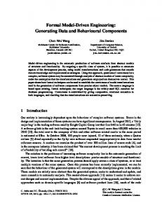
Fig. 1. Electron microscope images of vaterite spherules
Figure 1 shows electron microscope images of vaterite spheres produced by mixing aqueous solutions of CaCl2, K2CO3 and MgSO4 in a controlled way. Images of crushed spherules suggest an internal structure of nanoscale spheres arranged radially. The strong birefringence which they exhibit despite the spherical shape is evident in figure 2 which shows images of a rotating 6 micron diameter sphere between crossed polarisers.
Fig. 2. Crossed polariser images of rotating vaterite spherule at 150 intervals
Both the range of sizes available and the level of bifrefringence can be judged by inspection of Figure3, which shows the change in degree of circular polarisation observed in a trapping beam passing through vaterite spherules of different sizes. In this graph, 1 unit on the vertical axis corresponds to the particle acting as a quarter-wave plate, while 2 corresponds to reversal of the direction of circular polarisation, as by a half-wave plate. The dotted curve shows what would be expected for a similar thickness of material with the known birefringence of bulk vaterite. The structure of the spherules is still not completely understood, but we suspect that they are self-organised assemblies of nano-scale spheres, oriented into a sort of sheaf-of-wheat structure. The theoretical curve in figure 3 was based on such an assumption, using the theory described in a later section of this paper. On account of their high birefringence and spherical shape, the vaterite spheres are ideal test objects for microrheometry5, at least in solutions with a high pH. Since we can directly measure by purely optical means the optical torque acting, and the rotation speed, we can deduce the viscosity of the surrounding liquid to reasonable accuracy, since the drag coefficient of a sphere is well known. The fact that the vaterite spheres are soluble in acid solution and even in normal biological buffers is a serious problem but we have recently been able to overcome that as part of an effort to functionalise the spheres for attachment of proteins of interest.
Proc. of SPIE Vol. 7038 703816-2
2
4
2
II
Fig. 3. Birefringent retardation of vaterite spheres as a function of diameter
One of the aims of the process was therefore to coat the particles with a material dense and thick enough to prevent or at least radically reduce the ionic exchange between the calcium carbonate and the medium. A common method to functionalize the surface of microspheres is to apply a thin layer of aminopropyl silica (APS). APS is generally used for silica particles and is known to form a thin film, usually a monolayer of molecules, with primary (accessible for attachment) amine groups pointing outwards from the surface6. The primary amine groups would allow immobilization of a variety of molecules onto the surface. However, forming only a monolayer, the APS coating alone was not expected to provide sufficient protection for the beads. For this purpose, tetraethylorthosilicate (TEOS) was used to form a stable silica coating which later could be functionalized with APS. TEOS is commonly used to produce sub micron sized silica microspheres of controllable size through the well known Stöber process7. It has also been used to coat previously prepared silica spheres to create a core-shell structures where the shell may have different properties such as variable refractive index 8 or incorporated dye molecules 9. Using this process we have recently been able to fuctionalise vaterites with streptavidin and demonstrate their stability for periods of hours in biological buffer solutions10. This opens the way to a wide range of microbiomechanical experiments.
3. EXERTING TORQUE USING ORBITAL ANGULAR MOMENTUM Using orbital OAM it is possible to exert torques on non-birefringent objects, really anything which is not circularly symmetric. It is also possible for a beam to carry more OAM per photon: while circular polarisation carries a maximum of one ħ per photon of OAM, a high order Laguerre-Gauss beam can carry many units. However, coupling such beams to an object can be problematic, and direct measurement of orbital OAM remains difficult. We have made successful direct measurements of orbital OAM exchange in table-top experiments11 but have been unable to translate these to the highly focussed beams of optical tweezers. However, most asymmetric objects which can be turned using orbital OAM also exhibit some form birefringence that renders them susceptible to spin OAM exchange, which can be measured with reasonable accuracy. By measuring rotation speed with two handednesses of circular, as well as linear, polarisation, it is possible to calibrate the orbital OAM torque component against the measurable spin component12. Such torques can be exerted on naturally occurring asymmetric objects that have fibre or needle-like shapes, but recently we have begun to design and fabricate objects optimised for this purpose. The process we have chosen for fabrication is two-photon polymerisation of a UV curing optical resin. The photopolymerisation process is a particular type of radical chain polymerization, in which an initiator molecule produces a reactive centre in the form of a free radical. Polymerization occurs as a chain reaction by successive addition of monomers to the reactive centre. In the case of photopolymerization the reactive centre is produced by light absorption by the initiator molecule, which afterwards dissociates into a pair of free radicals. Based on this process,
Proc. of SPIE Vol. 7038 703816-3
some liquid resins can harden under UV exposure and thus one can create 3D microstructures from stacked 2D hardened elements, which are obtained from slicing the desired 3D shape of the structure in a computer-aided design program. The spatial resolution of the optically fabricated microstructures is determined by the size of the smallest solidified volume in the resin. One can substantially increase the resolution by using two-photon absorption of IR light instead of one-photon absorption of UV light, based on the fact that the two-photon absorption probability is proportional to the square of light intensity.The two-photon photopolymerization technique was pioneered by J. Strickler and W. Webb in 1991, following the application of two-photon excitation in laser scanning fluorescence microscopy13. The first 3D microfabricated structures with two-photon photopolymerization were reported in 199714. Since then, various micromachines have been produced (micropumps, microgears, microneedles) with resolution in the order of 100nm15. We use the NOA63 resin from Norland Products, which is based on a mixture of photoinitiator molecules and thiol-ene monomers. The photopolymerization setup is based on an “in house” built inverted microscope (Fig. 4).
P03
PBS P01
condenser
A/2 PBS Nd: '(AG
CCD Fig. 4. The optical system used to fabricate and test the rotating micromachines.
The 3D object is sliced into 2D layers (bitmap files) corresponding to the areas that need to be scanned. The program controlling the scanning stage reads the bitmap files and the resin is exposed (the shutter is opened) when the pixel in the bitmap is black and the shutter closes when the pixel is white. 3D structures are obtained by moving the sample in the Z direction after each XY scan. The bitmap resolution is set to 100x100 pixels which corresponds to 10x10 µm2 travel in X and Y directions. Hence each individual pixel is 100x100 nm2 in size giving a lateral resolution of 100 nm. The axial resolution is 200 nm given by the offset in the Z direction. The structures are grown upside down on the upper cover slip. This top down scanning method has the advantage that the laser beam does not pass through already exposed resin. After the polymerization, the unexposed resin is washed off with acetone, leaving the 3D structure attached to the cover slip. The 3D computer design and the 2D layers of our produced microrotors are shown in Fig. 5(a) and 5(b) respectively. The size of the squares defining the stalk is chosen to be 18x18 pixels and the cross is 54x54 pixels. The whole object is composed of 41 layers.The parameters for successful resin polymerization are 25 mW of average infrared laser power entering the microscope, 80 fs for the pulse duration and 8 W of pumping laser power. The scanning speed of the piezo stage is 14 µm/s, yielding a production time of 30 minutes per structure.
Proc. of SPIE Vol. 7038 703816-4
A typical SEM image of the fabricated structure is shown in Fig. 6, where the layer-by-layer formation of the microstructure can be clearly seen, as well as the firm attachment to the cover slip. We used a field emission SEM (JEOL JSM-6300F) operated at 15 kV for these experiments. The design of this object was based on the need for a central stem to stabilise the orientation within the trapping beam. For trapping experiments the object can be separated from the slide by pressure from a needle in a micromanipulator. The long axis aligns to the beam axis. The choice of four arms was based on the desire to couple optimally to an l=2 Laguerre-Gauss beam. In our experiments, the orbital torque was found by plotting the rotation frequency as a function of the measured spin torque per photon for three degrees of polarization imposed on the same LG02 beam. With a power of 40 mW, rotation frequency varied from 2.25 Hz (right circular) to 3 Hz (left circular) with an error of 5%. This implies that the orbital torque is 0.2 ± 0.03 h per photon, corresponding to an orbital torque transfer efficiency of 10%. This means that the orbital torque is 10 times higher than the spin component. Using the computational finite difference package FlexPDE, we were able to simulate the flow field around the rotating object and deduce the drag torque acting. For rotation at 2.75 Hz, this was found to be 5.4 pN.µm, which is in good agreement with the experimental value. This shows that the total optical torque exerted on micrometer sized objects rotating in an optical trap can be measured accurately by optical means, with an orbital angular momentum transfer ten times higher than the torque generated by the spin angular momentum.
80
70, 80, 00, 40, 30, 20,
ID,
(a)
U U
U
U
U
U
U
U
U
U
U
U ——
U
U
U
U
—I— —I— —I—
+++++UUUUU .
.
.
.
.
.
.
.
.
.
(b) Fig. 5.(a) rendering of object to be microfabricated, (b) bitmaps used to write the 41 layers of the object.
Proc. of SPIE Vol. 7038 703816-5
.
Fig. 6. Scanning electron microscope image of microfabricated rotor.
4. CALCULATION OF OPTICAL TORQUES The key to any engineering design is the ability to calculate the forces and torques involved. Although basic electromagnetic theory is well understood, calculating the interaction of a wavelength scale birefringent object with a highly focussed polarised light beam is nontrivial. Our approach is based on expansion of the fields in terms of vector spherical wavefunctions and then characterising the interaction in terms of a T-matrix linking the expansion coefficients of the incoming and scattered fields16. Once the fields are known, the momentum and angular momentum exchanged with the object can easily be found. However, the usual methods for calculation of the T-matrix fail for complex objects that depart too far from being spherical. For example, both the extended boundary condition method and our own pointmatching method fail for objects with aspect ratios beyond approximately 4. However, methods for solving general electromagnetic scattering problems can be adapted to the T-matrix formalism. We have done so for several structures, including the vaterite spherulites and photopolymerised micromachine elements, using two different methods: a hybrid finite-difference frequency domain /T-matrix17 method, and a discrete-dipole approximation/Tmatrix method. Both methods can be optimised to take advantage of symmetries of the structure, reducing the computational requirements in time and memory by orders of magnitude. Figure 2 shows the good agreement obtained for a hypothetical structure model of vaterite. Figure 7 shows a discrete-dipole model of a four-arm microrotor of the sort shown in figures 5 and 6.
Fig. 7. Discrete-dipole approximation model of a four-arm microrotor.
Proc. of SPIE Vol. 7038 703816-6
5. CONCLUSION Optical drive to rotating micromachines has been ‘proven in principle’ many times. We are now ready to move to the next stage with the ability to fabricate microscopic objects on which calculable and measurable torques can be exerted using either spin or orbital angular momentum.
6. REFERENCES 1. He, H., Heckenberg, N.R. and Rubinsztein-Dunlop, H. 1995. “Optical Particle Trapping with Higher Order Doughnut Beams Produced Using High Efficiency Computer Generated Holograms”. J. Mod. Opt. 42, 1, 217-223. 2. Friese, M.E.J., Nieminen, T., Heckenberg, N.R., and Rubinsztein-Dunlop, H. 1998 “Optical torque controlled by elliptical polarization”.. Opt. Lett. 23,1,1-3 3. Friese, M.E.J., Nieminen, T.A., Heckenberg, N.R., and Rubinsztein-Dunlop, H. 1998 “Alignment or spinning of laser-trapped microscopic waveplates”. Nature, 394, 348-350.(correction 395,621) 4. Nieminen, T.A., Heckenberg, N.R., and Rubinsztein-Dunlop, H. (2001) . “Optical measurement of microscopic torques”. J. Mod. Opt.48, 3, 405-413. 5. Bishop, A.I., Nieminen, T.A., Heckenberg, N.R., and Rubinsztein-Dunlop, H. 2004, “Optical microrheology using rotating lasertrapped particles”. Phys Rev.Letters, 92,19,198104 6. Ulman, A. (1996). “Formation and structure of self-assembled monolayers.” Chemical Reviews 96(4): 1533-1554 7. Stöber, W., A. Fink, et al. (1968). “Controlledgrowth of monodisperse silica spheres in micron size range, Journal of Colloid and Interface Science 26(1): 62 8. Rouse, J. H. and G. S. Ferguson (2003). “Preparation of thin silica films with controlled thickness and tunable refractive index.” Journal of the American Chemical Society 125(50): 15529-15536. 9. Lawrie, G. A., B. J. Battersby, et al. (2003). “Synthesis of optically complex core-shell colloidal suspensions: Pathways to multiplexed biological screening. Advanced Functional Materials” 13(11): 887-896). 10. Martin Persson, “Materials and Methods for Optical Manipulation of Single DNA Molecules”, Masters thesis,Royal Tech. Uni. Stockholm, 2007. 11. Parkin, S.J., Nieminen, T.A., Heckenberg, N.R., and Rubinsztein-Dunlop, H. 2004 “Optical measurement of torque exerted on an elongated object by a non-circular laser beam”. Phys. Rev. A 70, 023816 12. Parkin,S., Knoener, G, Nieminen, T., Heckenberg, N.R., Rubinsztein-Dunlop, H. 2006.“Measurement of the total optical angular momentum transfer in optical tweezers.” Optics Express 14, 15, 6963-70. 13. J. H. Strickler and W. W. Webb 1991 “Three dimensional optical data storage in refractive media by two-photon point excitation”, Optics Letters 16, 1780-1782. 14. S.Maruo, O. Nakamura, and S. Kawata, “Three dimensional microfabrication with two-photon-absorbed photopolymerisation”, Optics Letters22, 132-134,(1997) 15. P. Galajda and P. Ormos , “Complex micromachines produced and driven by light”, Applied Physics Letters78, 249-251(2001) 16. T.A.Nieminen et al., “Optical tweezers computational toolbox”, J. Opt. A, 9, S196-S203 (2007) 17. V.L.Y. Loke et al., “FDFD/T-matrix hybrid method“, JQSRT, 106, 274-284 (2007)
Proc. of SPIE Vol. 7038 703816-7