Estimation of Transformer Parameters and Loss Analysis for High Voltage Capacitor Charging Application
Prasanth Thummala, Henrik Schneider, Ziwei Ouyang, Zhe Zhang, and Michael A. E. Andersen Electronics Group, Department of Electrical Engineering Technical University of Denmark Oersteds Plads, Building 349, Kongens Lyngby, Denmark Email:
[email protected] , Homepage: http://www.dtu.dk/centre/elelEnglish.aspx Abstract-In
a
bi-directional
DC-DC
converter
The common goals of high voltage DC-DC power supplies are reliability, high efficiency, low cost, size and weight. The flyback topology is suitable for low power « 150 W) and high voltage applications, as it can be made very compact with a low number of components. The magnetic transformer is the most critical component in the HV flyback converter, its leakage inductance causes undesirable voltage spikes, and winding capacitance result in the undesirable current spikes, distortions in the waveforms of the converter, and slow rise times. These non-idealities in the transformer can lead to increased capacitive switching loss, snubber loss, winding loss due to skin and proximity effects, and variable core loss at high and variable frequency of operation, which might lead to reduced converter efficiency and reliability. So, accurate estimation of the transformer parameters, and individual losses in the converter are required to achieve an optimized design for this demanding application.
for
capacitive charging application, the losses associated with the transformer makes it a critical component. In order to calculate the transformer losses, its parameters such as AC
resistance, leakage inductance and self capacitance of the high voltage (HV) winding has to be estimated accurately. This paper analyzes the following losses of bi-directional flyback converter namely switching loss, conduction loss, gate drive loss, transformer core loss, and snubber loss,
etc. Iterative analysis of transformer parameters viz., AC resistance, leakage inductance and stray capacitance of the HV winding will lead to a considerable reduction in converter
losses. In this work, a 24 V to 2.5 kV bi
directional flyback converter has been implemented and the same has been used for loss calculation.
Keywords- high voltage bi-directional converter, capacitive load, AC resistance, core loss, stray capacitance, leakage inductance
I.
INTRODUCTION
High voltage switch mode power converters are used in a wide variety of capacitive charging applications. Typical applications include pulsed lasers, dielectric electro active polymer (DEAP) actuators, pulsed sonar equipment, photo flash systems, electric fences, and plasma research. Our research focus is to develop high voltage DC-DC power supplies as a driving mechanism for DEAP actuator applications [1]-[4].
Fig. I.
The converter efficiency can be improved by optImlzmg the whole converter design as well as with the proper selection of the control strategy. There is only limited research available in the literature, for an in depth optimization of a flyback transformer for the capacitive load charging and discharging application. In the future an efficiency optimization for this application will be carried out as an extension to the present research work. This paper is organized as follows. Section II describes the estimation of the HV transformer parameters. Section III summarizes the power loss modelling. Section IV discusses the details of the HV transformer design and the calculations are validated with measured data. Section V shows the experimental and simulation results, followed by the conclusion in Section VI.
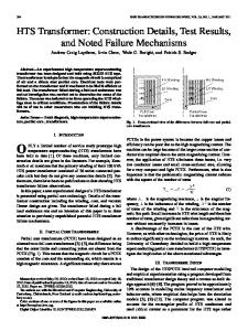
The DEAP material requires a high electric field strength of 60 VIpm and the thickness of polymer film is 40 pm therefore, a high voltage is needed for the DEAP actuator (is a pure capacitive load with very low leakage current) to achieve a reasonable actuation stroke. Thus specific component used in this study requires high voltage in the range of kilovolts ( 2.5 kV) at relatively low current. However, with the advanced research and development in high voltage devices like MOSFETS and diodes, it is possible to implement efficient and compact high voltage drivers, to drive and fulfil the requirements of DEAP actuator applications. An incremental DEAP actuator (Fig. I) which consists of 3 sub-actuators (2 grippers and 1 extender), is the load which needs to be driven by high voltage DC-DC converters. �
Danish National Advanced Technology Foundation (sponsor).
978-1-4799-0482-2/13/$31.00 ©2013
IEEE
Incremental DEAP actuator.
704
II.
HV TRANSFORMER PARAMETERS
ESTIMATION
nlphp
DC and AC resistances
A.
LIkp - flo
An increase in the switching frequency of the converter increases the transformer winding losses due to the skin and proximity effects. Since the converter operates under boundary mode during charging and in discontinuous conduction mode (DCM) during discharging, the AC conduction loss cannot be ignored and may dominate the total winding loss. The AC conduction loss is caused by high frequency skin and proximity effects, as well as the fringing effect. Due to its complexity fringing effect is not considered in this paper.
where
where, N
p
=
pl]p
A;
'
A
p
=
d
winding.
2 + ( nj, -
I
I
(nj, -
1)
( �:
J
is the permeability of free air, bw
RAe?
R;x'p
=
F.,')'kin
+
F?rox
= c G
n
nip
/ nls
primary/secondary layers,
hiP
/ his
and
in s'ulat(5r"
i
h"S 3-
i
insulato'r"
insulator
Vol
�
I
2 ·dv =-L1k 1 pk 2
rrsS-
�
Distribution
-�
NJ:
--
./
b)
�N, /'
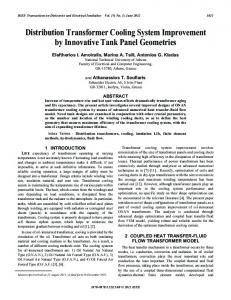
2) With interleaving: Practical experience revealed that interleaving the primary and secondary windings reduces the leakage inductance, self capacitance, and increases the interwinding capacitance. A transformer that is used in the HV application will have a lot of secondary windings, the interleaving structure with the secondary windings sandwiched between the primary winding as shown in Fig. 2b is typical for the high voltage DC-DC converter application. The general expression for the leakage inductance referred to the primary, for an interleaving winding structure where n ,) and nls2 secondary layers are at the top and bottom of a / primary winding respectively, having nip primary layers (with equal turns per layer of both, and no insulation between the primary layers) is derived in this work and is given by
is the number of layers
Ida
1) Without interleaving: The leakage inductance for the winding structure shown in Fig. 2a referred to primary is calculated using the energy stored in the magnetic field.
f B· H
the
Fig. 2. Analytical MMF distribution for non-interleaving structure P-S-SS-S-S (left) and interleaving S-S-S-P-S-S (right) structure.
In the tlyback converter the leakage inductance causes voltage spikes on the drain of low voltage and the high voltage MOSFETs, and may cause significant loss if the flyback transformer is not properly designed.
I
hi is
/' fN,I, /'
InsulatO'r"
B. Leakage Inductance
2
/'
�rl!latO'r"
I
mp
insulation
MMF
"F "
P 'V n
the porosity factor of the primary winding.
-
the
(5)
a)
=
IS
the number of
is the total length of
of the primary winding and t:l' is the primary winding conductor thickness normalized with respect to the conductor skin depth at the switching frequency for a round conductor, 51' is the skin depth at the fundamental frequency, and dj is
EMag
IS
p is the diameter of the primary
is the harmonic number,
(4)
the mean length
thickness between the primary/secondary layers, and
(2) where,
lw is
J
is the width of the bobbin window excluding
p"""-=
nip
+ hi
the edge isolation tape width,
The AC resistance of each harmonic in the current waveform can be calculated as [4], [5],
FH"" I,
l
6
insulation thickness between the primary and secondary layers, and Np is the number of primary turns.
p is the resistivity of copper at room temperature,
the primary winding, and
3
( 2n1P -1 )( nIP -1) ( h,p
The leakage inductance of transformer for the structure shown in Fig. 2 referred to primary is given by [6], [7]
4 ITP
nlsh, +
(1)
trd/
is the number of primary turns,
flo
I'
If
turn (ML T),
The DC resistance of the primary winding can be calculated by
RDep
�N 2 b
+
flJwN/ bw
(3)
----'-LIkp -
The general expression for the leakage inductance referred to the primary winding for a non-interleaving winding structure having nip primary layers and nls secondary layers (with equal
(6)
turns per layer) is derived in this work and is given by
705
The leakage inductance of the HV transformer for a simple interleaving structure shown in Fig. 2b is calculated using (7). J..l l . 2 =--N p 2 b o
L /
kp
C.
w
w
[
7h +35h, 6 . 13 . p +-h +-h 75 25 " 25'
]
(7) distance between the two layers, d, is the spacing between the centers of adjacent turns. The self capacitance of the HV winding for the winding structure shown in Fig. 4, and with the winding connections as shown in Fig. 3 is given by
Stray Capacitance
The stray capacitance is another important parameter in the HV transformer because it contributes to capacitive switching loss. The stray capacitance is calculated using the energy stored in the electric field [8] 1 1 2 D·E·dv =-c.t.V E}o.le (8) 2 Vo l 2
( 13)
=- f
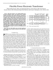
D. Trade-off between AC resistance, leakage inductance and stray capacitance for HV application 30 1--;==-==r==;:r ===:r:::==r==::I ===:;-r--� j ·.10 times of Leakage Inductance (�H) !'! 25 •• HV winding capacitance (pF) using (11)' l 2 •• HV winding capacitance (pF) using (1 ) I· 3 20 '* 1/10 th of AC resistance (ohm) " •
�
ro
...____________
Fig. 3.
�1
--'?w
� �
Voltage distribution in the secondary HV winding with the layers wounded in the same direction
lOr
l
r
l � JJ
'
£0
d o / dj is the outer/inner diameter of the HV winding conductor. The layer to layer capacitance is given by
/,.\"
"If
2
The self capacitance of the HV winding for the winding configuration shown in Fig. 3 is given by 51
= C4UI ( n - 1/ 2 n Is
l
t.,
J
2
( I I)
For the HV winding structure shown in Fig. 4, the layer to layer capacitance is given by [9], [10]
�
o
I==---=----,,=---=�
Fig. 4.
0.6
-,,·_,,·..••
���������j(o,ij �J , ,
0.65
0.7
0.75
Porosity Factor
0.9
Loss MODELING OF THE CONVERTER
In order to investigate the bi-directional converter efficiency, it is necessary to estimate the losses associated with each one of the circuit components in the converter. The schematic of the bi-directional flyback converter is shown in Fig. 6. The detailed analysis of the same converter is discussed in [13]. Different losses contributed from the transformer of the bi-directional flyback converter are given below.
where �s is the turns per layer of the HV winding.
c.
0.55
.
••_
. .. . ..... . .
::.:..... :. .�.. �.
.... . ...... . ....
III.
(10)
w
••
Fig. 5 shows the trade-off between the transformer parameters by changing the porosity factor. To show all the parameters in a single plot, the leakage inductance is multiplied by 10 and the AC resistance is divided by 10. The porosity factor (d; /do) is changed from 0.95 to 0.5 and the calculated parameters are shown in Fig. 5. It is observed that the AC resistance increases, and the self capacitance of the HV winding drops as the porosity factor is decreased.
is the aIr permitivity,
ILl =0J0,+6T1) (20,+I) CI
�.
Fig. 5. Trade-o±Ibetween the primary leakage inductance, secondary stray capacitance and the secondary AC resistance with a change in the porosity factor (d/do).
is the dielectric constant of the insulation of the winding,
C
5
85
(9)
S=COS-l 1- : In
i .l....�:I:�.... ::;;t:!...-. ...11= ........
..
(; 101'�
�
____________
The turn to turn capacitance per unit length of the non interleaved HV winding with a round conductor is given by
where
.'
\,.
A. Transformer winding loss The tlyback converter operates in boundary mode with variable switching frequency, while charging the capacitive load [13]. The primary winding power loss is given by [5]
_-JJ
I 2 2 PWP=RDCp I DCP+ ""2RDCP � -;2 FRP,/pn
- CU2
(14)
By applying the Fourier series expansion for the primary current waveform shown in Fig. 7 the following equations are obtained:
A random HV winding arrangement
706
IDcr =
(lpk-lrnin) DonC 2
2
Irn = �a n +bn2
(15)
The most commonly used expression for the time-average core loss calculation per unit volume, for the sinusoidal excitation is the Steinmetz equation given by
(16)
Pv = kr B
dt
Fig. 8 .
BD(t)
Fig.
Ipk1'
OFF
Fig.
�r-----�------� t Tsc
{�. {
I,�+�m X 2 2 2Jr n DonC an = Jrn cos ( 2Jr n Donc) -1+ (2JrnDonc) sin ( 2Jr n Donc ) ] sin ( 2Jr nDone_)+
}
[
.
I"k +Imin
I !..-cos ( 2JrnD X ---'!"! on!_ ) + 2 2 2Jr non D e Jrn
[ sin ( 2JrnD onc )-( 2JrnD onc ) cos ( 2JrnD onc ) ] IDcr' IpkJ" Imin, RDCl" IRMsr
and
}
9.
Flux density waveform during the discharging mode.
The core loss per unit volume due to non-sinusoidal excitation is calculated using the improved generalized Steinmetz equation (IGSE) [10] which is given by
Primary current waveform while charging the capacitive load.
----l!2!!2...
where
Flux density waveform during the charging mode.
�__-'__-+____��______'-____I'�t 1 1 1 1 1 1 1 Cycle2 ,1
Bi-directional flyback converter for capacitive load [13] .
ON
bn =
(19)
ON
6.
Fig. 7.
(�%)fi
Pv
(17)
=
� T
d ( fki � (Ml-U dt ,k, dt
IT I )lrI
l
0
where k ,
=
(2JZ" )"-'
k
f leos Blu 2fl-u dB 'If
(20)
a and fJ are the constants provided by the
manufacturer, M is the peak-to-peak flux density of the current excitation. The angle e represents the phase angle of the sinusoidal waveform. Figs. 8 and 9 show the flux density waveforms during charging and discharging modes. The core loss per unit volume during the charge operation in each switching cycle is given by
(18)
RACT are the primary
winding DC current, peak current, negative current at the beginning of the turn-on process, DC resistance, rms current, and AC resistance (given by (2)) respectively. Irn is the current amplitude of the nth harmonic. is the on-time
P.e =
;I" ce [( BrnC+Bne l'
.
l tone -a,
+ Bm/'
.
l to{Jc -a,
]
(21)
Similarly the core loss per unit volume during the discharge operation in each switching cycle is given by
DonC
fiD
duty cycle during charging process. The secondary winding power loss can also be calculated using the above approach. The negative current at the beginning of the turn-on process (Fig. 7.) is because of the HV winding capacitance. When the secondary winding current becomes zero, the drain to source voltage tends to drop. Since the control IC L T375 I [14] that is used, operates under boundary mode control, the next switching cycle starts before the HV winding capacitance completely discharges. So current flows in the negative direction to discharge the HV winding capacitance at the start.
PvD = kIDBrnD tonDI-aD +to I-aD (22) rfD TsD with kic, fJc' ac' Tic, Bme, tonc' toiTC / kiD' fJD' aD' T,D' BrnD, tonD' toJjD
[
]
as the core loss constants, switching period in each cycle, peak flux density, on-time and off-time in each switching cycle during charging/discharging modes respectively. C.
Losses in the bi-directional flyback converter excluding the magnetic losses
Different losses associated with the bi-directional flyback converter are provided in Table I. The loss distribution can be made after calculating all those losses. The results of the loss analysis are shown in Section V.
B. Transformer core loss The core loss calculation during the charging process needs to take care of the variable switching frequency of operation.
707
TABLE I.
DIFFERENT LOSSES IN THE BI-DIRECTIONAL FLYBACK CONVERTER DURING CHARGE AND DISCHARGE OPERATIONS
Abbreviations
Power loss expression
Type of power loss
Low voltage MOSFET
. P.",1'
=
f
ml c
HVMOSFET
J n =---" "---
P
,,11
Low voltage MOSFET
P,p
Diode
Body diode of voltage MOSFET
l
J
+
]
(CwS +Co"s )��p +
P
=
(
J ( J
. sensel'C 'wowP
3
� �=
Gate driver loss
- output capacitance of the primary/secondary
�};P/Vd,S - primary/secondary MOSFET drain to source voltage
�HTJ.\.11 =
Snubber loss
RCD snubber across secondary winding
Jwc / JW/J - switching frequency during charging/discharging
- primary/secondary rms current during charging mode
JRMSPD /IRMSSD
fl�Hssc
Power consumption in the two control Ie's
IV.
t
- ,
I
rms
current
during
/ IRMSSC
-
average/nns current through the HV diode
during charging
/ IRMSS D - average/nns current through the HV diode
DCSD
Db
rD - HV diode on resistance
Vi", - forward voltage drop of body diode of M I
DCPD
Q
"
- average current through primary during discharging
/ Donn - on-duty cycle during charging/discharging
/t,, - reverse recovery charge/time in the high voltage
diode D2 i, - secondary current,
dt
V,,,,, /V;,
,
= Vcs (QCM fsjjD +QCMl /;WC ) 2
v,JS
- outputlinput voltage of flyback converter
- gate drive voltage of the MOSFET
QGJL/QGM,
- gate charge for high voltage/low voltage
MOSFETS
pmLV -
p.\'IIrn" 1.. LlC' ['pC") V,
2
PCa,'",,,,,
primary/secondary
during discharging
1+1"
f
-
- HV diode forward voltage drop
DCSC
n
Q". =
- on-resistance of the primary/secondary MOSFET
,/,
D,
fTXPTJ
e
=
�," = Va., +n v'.
operation n - turns ratio of the transformer from secondary to primary
I
P" = Q, (V"", +n � ) 1",
RC snubber across primaryMOSFET
i
Vd,P =VIn + �' ' n '
VI"
� IJb = Vii)ITX'sn +rn I�,\lssTJ
PCate
transformer
MOSFET
Do e n
Reverse recovery loss ofHV diode
the
1m", - negative current at the beginning of the turn-on process
D UIID
+ rD
D
low
of
discharging mode
�I!\1sPDr"
P w""PD -
= I�k)/)
Db
capacitance
t;f / t" - current fall/voltage rise transition times of the
?'s =I�;"",r",
D2
self
-
corresponding MOSFETs
,�I�c D'"'�C-" +�" JL 3 T,c 3 T,c
' . Jll,\f;,n
HVMOSFET
Diode
(Cw" +C""" )
2 V:t.,,-,Ip( kSD t,r +tlW )
Sense resistor on the primary side
HV diode
Cw,,/Cws
primary/secondary
2 �"plp( "pc tif +t,.,. )
Switching loss
Conduction loss
The subscript 'P' / 'S' or 'C' / 'D' in any variable represents that variable is being referred to primary / secondary side or that variable during charging and discharging modes
v"omp -nVm
'dm."
Cm -snubber capacitance in the RC snubber
I",n
= 2�JQ
- clamping voltage of the RCD snubber
V" - 1 C supply voltage
IQ - quiescent current of V,., operating points. High voltage capacitor charging application requires proper design of the transformer, otherwise significant amount of energy is lost and efficiency will suffer. The parameters that significantly affect the efficiency of the converter for capacitor charging application are the peak current, MOSFET type, transformer type and size, magnetizing
HV TRANSFORMERDESIGN: COMPARISON OF MEASUREMENTS AND CALCULATIONS
Since the proposed DC-DC converter operates in a wide output voltage range (0-2.5 kV), to charge and discharge the DEAF actuator employed in a specific application, different components of the converter have to be designed for different
708
TABLE V.
inductance, the turns ratio, air-gap length, AC resistance, leakage inductance, and HV winding capacitance. V.
INTERLEAVING STRUCTURE
Primary turns (Np) / Secondary turns
50
I
Discharging energy efficiency: experiment
•
DC resistance of primary (Rdcp) / secondary winding (Rd••S)
62mO / 28. 5 0 I /5
Turns per layer of primary (Tip) / secondary (h,)
16 / 75
Each layer primary (hI') / secondary winding thickness (h,)
0. 5 mm / 0. 1 mm
Insulation thickness between secondary layers (h,)
0. 1 mm (Kapton Tape)
Dielectric constant of the insulation of the HV winding (c,.)
2500
16.29 pF / 41 pF
Primary (nip) / Secondary layers (n,,)
Trans±ormer edge isolation tape width
2000
16/ 375
1.11 JlH / 633 JlH
energy efficiency: calculation
500
28 JlH / 15. 3 mH
Leakage inductance of transformer primary (L",r) / secondary (L,kl)
Insulation thickness between the primary layer and the adjacent secondary layer (h)
Charging energy efficiency: experiment
• Charging energy efficiency: calculation
c uu
(Ns)
Secondary winding self (C,) / Interwinding capacitance (C,n')
:� - .S'? I: '-';l5I:O:w q::.:JI::fI!�'k!�rw
70- () • c . � 60
E> Q)
Value EF20 / N87
Primary (LmP) / Secondary magnetizing inductance (Lms)
100,------,--�--"
IE uu
Parameter Flyback transformer core type / Material
EXPERIMENTAL AND SIMULATION RESULTS
The specifications of the bi-directional flyback converter and the components used in it are provided in Tables II and III respectively. The flyback transformer parameters are shown in Tables V. The experimental prototype is shown in Fig. 11. A boundary mode controller LT3751 has been used for performing both charging and discharging operations. The bi directional flyback converter charge and discharge cycles are controlled using a microcontroller. Table IV presents the components used in the bi-directional tlyback converter. Fig. 10 shows the comparison of the calculated and measured charging and discharging energy efficiencies of the converter. The energy efficiency definitions can be obtained from [13].
�
FLYBACK TRANSFORMER PARAMETERS WITH NON
0. 3mm
1.6mm So,bw = bw-2x1.6mm 3. 5
Fig. 10. Comparison of the experimental and the calculated charging and discharging energy e±Iiciencies tor a non-interleaved transformer. TABLE I!
BI-DIRECTIONAL FLYBACK CONVERTER SPECIFICATIONS
Parameter
Value
Input voltage
24 V
Output voltage
0-2500 V
Stored energy in the load at 2. 5 kV
0.625.1
output voltage
Fig. I I.
Capacitance of the film capacitive load
200 nF
Primary peak current during
4.24 A /
charging/discharging
5. 3 A
TABLE III.
=
CONVERTER
Component
Name
HV diode Film capacitor load
STB50NF25 [250 V, 45 A, 55 mOl IXTV03N400S r4 kV, 300 mA, 290 01 SP5LFG [5 kV, 400 mA, 50 ns(t,,)] WIMA [200 nF , 3 kV]
Analog control IC
LT 3751
HV MOSFET
TABLE IV.
·�0���Oc���51��� ·���r���:et�!rir::i�or Primary MOSFET .dri ving loss
COMPARISON OF HV TRANSFORMER PARAMETERS
Parameter DC resistance of secondary winding of trans±onner (0) Leakage inductance of primary winding of transformer (JlH) Self capacitance of HV winding (PF)
Calculation
Measurement
23
27. 5
1.09
1.11
Eq. (11) I 17. 65
I
Eq. (13) 13. 58
Ave rage loss distribution during charging 2%2% %
_ _ _ _ _ _ _ _ _ _ _ _ _ -, .Transformer copper loss .Transformer core l oss .Switc hing loss of primary MOSFET .Conduc tion loss of primary MOSFET ORC snubber l oss
COMPONENTS USED IN THE BI-DIRECTIONAL FLYBACK
Low voltage MOSFET
Picture of the experimental setup.
Fig.
12.
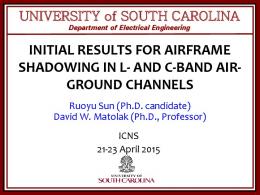
Average loss distribution during charging of capacitive load.
All loss calculations are done in Matlab. The average loss distributions of the bi-directional flyback converter during charging and discharging modes are shown in Figs. 12 and 13 respectively. Fig. 14 provides the comparison of the average power losses during charging and discharging modes. The peak current of the primary MOSFET has been changed, and
16.29 709
VI.
the charging energy efficiency variation has been provided in Fig. 15. In Fig. 16 we show the variation of the energy efficiency with the porosity factor. At high porosity factor the HV winding capacitance is high, so the discharging energy efficiency at 2.5 kV is low compared to that at medium porosity factor. However, at low porosity factor, the AC/DC resistance increases, so both charging and discharging energy efficiencies will drop.
The power losses in the bi-directional flyback converter for the capacitor charging application has been analyzed in detail. Due to the variable switching frequency and non sinusoidal waveforms, it is very difficult to accurately compute the core and winding losses. The core loss was accurately calculated during charge and discharge operations, using piecewise linear approximation of the IGSE model. Estimation of the leakage inductance for a non-interleaved structure and an interleaved winding structure has been discussed. Stray capacitance calculation for a typical HV winding structure is discussed. Trade-off between the different transformer parameters has been made with respect to porosity factor. Comparison of the measurement efficiency and the calculated efficiency shows the accuracy of the proposed loss analysis. The future work involves the optimization of the whole converter with mostly focusing on transformer optimization.
Average loss distribution during discharging
ii����c�o�p�pe:r"lo:s�s----1 .Transformer core l oss ni g l oss of .hiSwigthch votl age (4kV) MOSFET toi n loss of .hiConduc g hvotl age (4kV) MOSFET DHV RCD sn ubber loss d s e es .�� �� �g���; c o �� uc ��� loss • conductoi n loss of body diode of primary MOSFET .HV(4kV) MOSFET driv ni g loss
Fig. 13.
Average loss distribution during discharging of capacitive load.
REFERENCES
.1. Average Transformer copper loss • 2. Average Transformer core loss
[I]
04. Average Switching loss
D3. Average Conduction loss of
[2]
Snubber Losses
'" '" o ...J
[3]
�o
a.
[4]
4 Type of Power Loss
[5] Fig. 14. Comparison of the average loss; On Y-axis, 1 and 2-corresponds to power loss during charging and discharging respectively.
"1� L- ·
�
80 70 60 w 50 40� � 30 w 20 3
·
ai �
Fig. 15.
� 0.9
'
•
:
'
.
'
70
.
[7]
' 60
'.
[8]
40 .5
R Pelrine, P S. Larsen, R. Kornbluh, R Heydt, G. Kofod, Q Pei, P Gravesen, "Applications of dielectric elastomer actuators, " in Proc. SPIE, voL 4329, pp. 335-349, 2001. M. Tryson, H. E. Kiil, and M. Benslimane, "Powerful tubular core free dielectric electro activate polymer (DEAP) push actuator, " in Proc. SPIE voL 7287, p. 72871F, 2009.
P. Thummala, L. Huang, Z Zhang and M. A E. Andersen, "Analysis of Dielectric Electro Active Polymer Actuator and its High Voltage Driving Circuits, " in Proc. IPMHVC. pp. , Jun. 4-7, 2012. P. Thummala, Z Zhang, M. A E. Andersen, 0 C. Thomsen, "A high voltage DC-DC converter driving a Dielectric Electro Active Polymer actuator for wind turbine flaps, " in Proc. UPEC pp. l,7, 4-7 Sept. 2012.
W.G. Hurley, E. Gath, J G. Breslin, "Optimizing the AC resistance of multilayer transformer windings with arbitrary current waveforms, " IEEE Trans. Power Electronics, v01.15, no.2, pp. 369-376, Mar 2000. D. Murthy-Bellur, M. K. Kazimierczuk, "Winding losses caused by harmonics in high-frequency flyback transformers for pulse-width modulated dc-dc converters in discontinuous conduction mode, " lET Trans. Power ElectroniCS, voU, no. 5, pp.804,817, September 2010.
.I. Zhang, Z. Ouyang, M. Duffy, M. A. E Andersen and W. G. Hurley
"Leakage inductance calculation for planar transformer with magnetic shunt ", inProc. ECCE USA 2013 (accepted).
50
2. 5
2 -----____. ' .5 output Voltage (kV),-
[6]
80
,
CONCLUS10N
Primary Peak Current (A)
[9]
3D plot showing how the peak current affects the charging energy.
Z. Ouyang, O. C. Thomsen, M. A. E. Andersen, 'The analysis and comparison of leakage inductance in different winding arrangements for planar transformer ", in Proc. IEEE PEDS, pp. 1143-1148, Nov. 2009. L. Dalessandro, F. da Silveira Cava1cante, .I. W. Kolar, "Self Capacitance of High-Voltage Transformers, " IEEE Trans. On Power Electronics. Vol. 22, no. 5, pp. 2081-2092, Sept. 2007.
"
[10] .I. Biela, .I. W. Kolar, "Using Transformer Parasitics for Resonant Converters-A Review of the Calculation of the Stray Capacitance of Transformers, " IEEE Trans. on Industry Applications, , vol. 44, no. I, pp. 223-233, 2008.
� 0.7
[11] E. C. Snelling, Soft Ferrites-Properties and applications. 2nd ed. London, UK, Butterworth, 1988.
�
�O.8 o
� '"
(;' �
[12] K. Venkatachalam, C. R. Sullivan, T. Abdallah, and H. Tacca, "Accurate prediction of ferrite cores loss with nonsinusoidal waveforms using only Steinmetz parameters, " in Proc. IEEE Workshop Comput. Power Electron., pp. 36-41, 2002.
� 0.6 '" � �
w
[13] P. Thummala, Z. Zhang and M. A. E. Andersen, "Bi-directional Flyback Converter for Capacitive Actuator ", in Proc. EPE 2013 (accepted).
°ii":'---;O"' .2:-----: : 0"'.3-- 0 ;;'"-.4-;-----= 0"'= . 5'-----=' 0.""6---;0"'. 7 =----=-';;-� Porosity factor
Fig. 16.
[14] L T3751, "High voltage capacitor charger controller with regulation, " datasheet.
Variation of energy etliciency at 2. 5 kV with porosity factor (d/d,,)
710