Aug 5, 2007 - Our major contribution is to show how three extra modes can be .... decoded using the regular individual m
Graphics Hardware (2007) Timo Aila and Mark Segal (Editors)
ETC2: Texture Compression using Invalid Combinations Jacob Ström and Martin Pettersson Ericsson Research
Abstract We present a novel texture compression system for improved image quality. Building on the iPACKMAN/ETC method, bit combinations that are invalid in that system are used to allow for three additional decompression modes without increasing the bit rate. These modes increase quality, especially for color edges and blocks with smoothly varying content. Due to the use of invalid bit combinations, the system, called ETC2, is backwards compatible with iPACKMAN/ETC. It outperforms S3TC/DXTC and iPACKMAN/ETC in terms of PSNR with 0.8 dB and 1.0 dB respectively, which is clearly visible to the human eye. Categories and Subject Descriptors (according to ACM CCS): I.3.7 [Computer Graphics]: Texture
1. Introduction The factor limiting performance in rasterization-based rendering hardware is usually bandwidth [AMN03]. As shown by Knittel et al. [KSKS96], Beers et al [BAC96] and Torborg and Kajiya [TK96], texture compression can be used to reduce bandwidth usage. Our new texture compression system is built on the iPACKMAN/ETC system (from hereon referred to as Ericsson Texture Compression, ETC) [SAM05], and designed to take care of the blocks that ETC has most difficulties with. Our major contribution is to show how three extra modes can be added by the use of invalid bit combinations, while keeping backwards compatibility and without increasing the bit rate. Another contribution is the extra modes themselves—two of them are versions of modes that have been published earlier by us [PS05], but for a smaller audience. The last mode has not been presented before.
2. Previous Work Delp and Michell [DM79] present block truncation coding (BTC) for compression of gray scale images to 2 bits per pixel (bpp). The image is divided into 4 × 4 blocks, and two shades of gray are encoded in the block, together with a bit mask that decides for each pixel what shade to choose. The method by Campbell et al [CDF∗ 86]—Color Cell Compression (CCC), extends BTC to color. Each 4 × 4 block includes two colors instead of two gray scales. By using a 256-wide color palette, the colors can be represented with eight bits each, yielding 2 bpp for color images. However, having only two colors per block limits image quality, and having a color palette is a drawback in today’s systems, where memory accesses are slow in relation to computation. The de facto standard today is the S3TC/DXTC texture compression method c 2007 by the Association for Computing Machinery, Inc. Copyright Permission to make digital or hard copies of part or all of this work for personal or classroom use is granted without fee provided that copies are not made or distributed for commercial advantage and that copies bear this notice and the full citation on the first page. Copyrights for components of this work owned by others than ACM must be honored. Abstracting with credit is permitted. To copy otherwise, to republish, to post on servers, or to redistribute to lists, requires prior specific permission and/or a fee. Request permissions from Permissions Dept, ACM Inc., fax +1 (212) 869-0481 or e-mail
[email protected]. GH 2007, San Diego, California, August 04 - 05, 2007 c 2007 ACM 978-1-59593-625-7/07/0008 $ 5.00
by Iourcha et al. [INH99], and it can be seen as an extension of CCC. Two colors in RGB565 format are stored in the block, and two more colors are interpolated in-between. Thus each pixel can choose from four colors, yielding better image quality than CCC without the need for a color palette. With 64 bits per 4 × 4 block, the rate of S3TC is 4 bpp. Beers et al. [BAC96] use vector quantization for texture compression to reach compression rates of 1-2 bpp. However, this requires a big LUT, which introduces indirect addressing resulting in latencies that can be hard to hide. Fenney [Fen03] uses two low-resolution images A and B, both upscaled bilinearly two times. Each pixel can then choose its color from either image A, image B, or from two blend values between A and B. A 2 bpp version and a 4 bpp version exist. ATI has created a system for texture compression called ATI-TC, that they have integrated in their texture compression tool “The Compressonator”. We have not found any public information about this codec, but we have compared against the 4-bpp version of ATI-TC in our results section. Whereas most texture compression methods are using a fixed number of bits per block, Inada and McCool [IM06] use variable bit rate coding. They achieve random access through a B-tree index. The system is for lossless coding, but could in principle be used for lossy coding as well. If used lossily, the system would likely have a higher compression efficiency (quality per bit) than fixed rate coding systems, since it would be possible to save bits on “easy” areas and instead spend them on “hard” areas. However, the B-tree index means that the caching structure must be changed, and in this paper we concentrate on algorithms that can be used in lieu of today’s de facto texture compression standards without such architectural changes. Munkberg et al. show how new modes can be added in a fixed rate codec by the use of the ordering trick from S3TC [MAMS06]. Our work is similar in spirit, but
Jacob Ström and Martin Pettersson / ETC2: Texture Compression using Invalid Combinations
color
luminance
final image
differential dR1
G0
dG1
B0
dB1
5
3
5
3
5
3
R0
R1
G0
G1
B0
B1
4
4
4
4
4
4
bit size
+
=
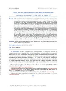
uses invalid bit sequences instead of redundant ones. Since our work is an extension of the PACKMAN [SAM04] and ETC algorithms, we will go through them in more detail in the next section. 3. PACKMAN and ETC The PACKMAN algorithm exploits the fact that the human visual system is more sensitive to changes in luminance than in chrominance. It takes the rather radical approach of only having a single chrominance per 2 × 4 pixel block, represented as a RGB444 color (12 bits). Each pixel can then modify the luminance of this base color additively, as shown in Figure 1. More specifically, a modifier value is added to all three components (R, G and B) of the base color. The modifier value is taken from a small table of four entries, and hence two bits, called pixel indices are needed to select the value for each pixel. Four bits are spent on a table codeword, to select the table from 16 prefixed tables. Altogether, 32 bits are used for 2 × 4 pixels, giving a rate of 4 bpp. 3.1. ETC PACKMAN has been improved under the name iPACKMAN (here called ETC) in two ways [SAM05]. First and most important, a differential mode is introduced, allowing two neighboring 2 × 4 blocks to be coded together. The base color of the left block can then be encoded using RGB555, i.e., with higher precision, and the right base color also in RGB555 format, but coded using a differential dRdGdB333, where dR, dG and dB can assume values between −4 and +3. Thus, for pairs of blocks with similar base colors, the chrominance resolution effectively goes up from RGB444 to RGB555 in both blocks. Blocks that cannot be encoded well using the differential mode will be coded as before, i.e., with two individually coded RGB444 colors. This mode is called the individual mode. The second improvement is that blocks can be flipped so that a 4 × 4 block consists of either two 2 × 4 block next to each other, or two 4 × 2 blocks on top of each other. Two mode bits are needed, one to choose between individual and differential mode, and one to indicate the flip status. Space for these two bits are created by shrinking the number of possible tables from 16 to eight, thus reducing the number of table bits in
table 0 table 1 3
3
individual
bit size
Figure 1: The core idea of PACKMAN. Left: The base color for each 2 × 4 block. Middle: Per-pixel luminance modulation. Right: The final image.
diff
R0
flip pixel indices 1 32 1 1
diff table 0 table 1 3
3
flip pixel indices 0 1 1 32
Figure 2: Modes in original iPACKMAN. Top: Differential mode. Bottom: Individual mode.
each sub-block from four to three. Figure 2 shows the bit layout in the differential (top) and the individual (bottom) modes. These two small changes greatly affects image quality, which jumps 2.5 dB in terms of Peak Signal to Noise Ratio (PSNR), suddenly putting ETC on par with S3TC. Visually, ETC lacks the disturbing banding artifacts that are a result of the low chrominance resolution in PACKMAN. Still, only one chrominance can be used for an eight-pixel block. 4. Invalid Bit Sequences One major contribution of this paper is to show how invalid bit combinations can be used to improve ETC. This idea is related to the ordering trick that has been used in DXT1 to select the one-bit alpha mode for RGBA textures, or alternatively, for RGB textures, to select a mode where the third color is (col0 + col1)/2 and the fourth color is black (0, 0, 0). It has also been used by Munkberg et al. in order to increase the number of modes in a normal map compression system [MAMS06]. The ordering trick exploits the fact that there are redundant bit sequences—i.e., two different bit sequences will result in exactly the same decompressed block. Since only one representation is necessary, the other bit sequence can be used for something else, such as signalling an alpha mode. For ETC we have not found any interesting redundant bit sequences, so instead we concentrate on invalid bit sequences. For instance, in the differential mode of ETC, the second red component R1 is calculated as R0 plus a delta, R1 = R0 + dR. Here R0 is a five bit number between [0, 31] and dR is a three bit number between [−4, 3]. But R1 should also be between [0, 31], and thus the addition can both overflow and underflow. Since intensities smaller than zero (or larger than the maximum) are not physically meaningful, these representations are invalid. They can thus signal that the bits of the blocks should be interpreted in a new way, and not be decoded using the regular ETC logic. Figure 3 shows how the decompression of such a system could work. If the diffbit is not set, the 63 remaining bits are decoded using the regular individual mode from ETC. If the diffbit is set, however, we first see whether the addition R1 = R0+dR underflows or overflows. (From now on, we will just use the term overflow for both under- and overflows.) If we are not overflowing, we are decoding the 63 bits the usual c Association for Computing Machinery, Inc. 2007.
Jacob Ström and Martin Pettersson / ETC2: Texture Compression using Invalid Combinations Is DIFFBIT set? no
yes
decode remaining 63 bits using the individual mode
Is R0 + dR in [0, 31]? yes decode remaining 63 bits using the differential mode
no decode remaining 63 - 8 = 55 bits using an auxiliary mode
Figure 3: Example of a decoder that uses invalid bit sequences. If the addition stays in the legal range, the regular differential decompression is used. However, if the addition overflows, the block is decoded in an auxiliary way.
way, using the differential mode from ETC. However, if the sum overflows, we decode the bits in an alternate way. The bits representing R0 and dR (eight in total) are used to signal the overflow, and the diffbit must be set to 1, but the other 64 − 8 − 1 = 55 bits can be used for this auxiliary mode. We say that we have a payload of 55 bits in the auxiliary mode. In fact it is possible to increase the payload. We have refrained from using any of the eight bits in R0 and dR, but that is over-zealous: As can be seen in the first two columns of Table 1, R1 = R0 + dR can overflow in exactly 16 ways, and this means that we should be able to store four bits there by selecting which of the 16 overflow bit strings to encode. For instance, to encode the 4-bit string 1001bin (last column), we
choose R0 = 2(= 00010bin ) and dR = −3(= 101bin ). When decoding, we look up the concatenated overflowing string 00010 101 in the table and get back 1001. Due to the way the rows in the table are ordered, the bits in the 4-bits string are just the underlined bits in the 8-bit field. Thus the decoding process is yet simpler—we just take the underlined bits from the overflowing string 00010 101 to get the 4-bit string 1001. In this way, we have increased the payload in our auxiliary mode from 55 bits to 59. So far we have only used the red component, so it is natural to investigate whether it is possible to exploit overflow in the green- and blue components to have even more modes. For this to work, we must make sure that red does not overflow—otherwise the decoding process will select that mode. Looking again at the third column in Table 1, we see that the two first bits are always the same for all overflowing modes. By setting the first bit in R0 different from the second bit in R0, it is thus possible to make sure that R0 + dR never overflows. This means that a new mode can be constructed, where red does not overflow, but green does. Since one bit is lost making sure that the red component does not overflow, this auxiliary mode will have a payload of 59-1 = 58 bits. Analogously, it is possible to construct a third mode, where red and green does not overflow, but blue does, and this mode will have a payload of 57 bits. The decoding is diffbit no yes yes yes yes
redOF yes no no no
greenOF yes no no
blueOF yes no
decode using individual mode 59-bit mode 58-bit mode 57-bit mode differential mode
Table 2: Mode selection based on the diffbit and overflows. R0 0 0 0 0 1 1 1 29 2 2 30 30 3 31 31 31
dR -4 -3 -2 -1 -4 -3 -2 3 -4 -3 2 3 -4 1 2 3
R0 dR binary 00000 100 00000 101 00000 110 00000 111 00001 100 00001 101 00001 110 11101 011 00010 100 00010 101 11110 010 11110 011 00011 100 11111 001 11111 010 11111 011
4-bit string 0000 0001 0010 0011 0100 0101 0110 0111 1000 1001 1010 1011 1100 1101 1110 1111
Table 1: The table shows all 8-bit strings that overflow. Four bits can be encoded by selecting the appropriate 8-bit binary overflow code. To decode, the underlined bits in the 8-bit code are used to obtain the 4-bit code. c Association for Computing Machinery, Inc. 2007.
performed according to Table 2. For instance, if the diffbit is set and red does not overflow but green does, the 58-bit mode is used (irrespectively if blue overflows or not). Note that if an old ETC texture is passed into this decoder, it will end up in the top or bottom row, since the colors never overflow. Thus, our new system is backwards compatible. 5. New Modes in ETC2 We now have room for three new modes of 59, 58 and 57 bits respectively. Ideally, the new modes should be good at compressing blocks for which ETC performs poorly. Examples are blocks with two distinctly different chrominances, such as in the leftmost image in Figure 8, and slowly varying chrominance changes, shown in the second image. In the development process, we have experimented with a wide variety of algorithms, and the three modes that we are describing here are the ones that turned out to work best. Two of these have been presented by us in a previous paper [PS05], and the third is novel.
Jacob Ström and Martin Pettersson / ETC2: Texture Compression using Invalid Combinations
A problematic block taken from the leftmost image of Figure 8 can look like the left diagram in Figure 4 where the colors are plotted in RGB-space. (The green dimension is not shown for simplicity.) Note how most of the colors are in the top left group (different intensities of yellow, not visible in B/W reproduction), which would suggest that regular ETC compression would work quite well with intensity variation of a yellow base color. However, some of the pixels are of a rather different color, which breaks the ETC model. For this reason, the T-mode was introduced. Each pixel can here choose from four paint colors. Three of the paint colors are obtained by modifying the first base color along the intensity direction by adding the vectors (−d, −d, −d), (0, 0, 0) or (d, d, d) to the base color. The distance d is obtained from a small look-up table. The fourth paint color is just the second base color unmodified. The pattern, which is shown in the rightmost diagram in Figure 4, can resemble the letter “T”, hence the name. We propose to use the T-mode for the 59-bit slot, using RGB444 for the two base colors, and specifying the distance d with three bits using the following small
Sometimes there are two groups of colors for which intensity modulation could be useful, as illustrated in the left diagram in Figure 5. It is then possible to modulate both base colors with the vectors (−d, −d, −d) and (d, d, d) to produce the four paint colors, as seen in the right diagram in the same figure. This mode is called the H-mode, since the
d d
R
R d d
B
B
Figure 5: Left: The colors can be arranged in two groups so that intensity modulation works well on both groups. Right: Two base colors (marked with squares) are selected. Four paint colors (marked with circles) are derived by adding a distance d in direction (1, 1, 1) to form an H-pattern.
d
d
R
R
is used to select one of the four paint colors. For instance, the first index is 01 which means that the second paint color (68, 68, 85) is used for this pixel.
look-up table (LUT): {3, 6, 11, 16, 23, 32, 41, 64}. The same LUT is used for all T-mode blocks in all textures, and can therefore be kept on chip and hardwired. Since two bits per pixel is enough to choose from the four paint colors, we need 12 × 2 + 3 + 16 × 2 = 59 bits, just fitting the 59-bit slot.
pattern can resemble the letter “H”. Using RGB444 for both base colors, and two bits per pixel to specify the paint color, we only have 58 − 12 × 2 − 2 × 16 = 2 bits left to specify the distance d, if we want to fit it in the bit budget of the 58-bit mode. However, since the H-pattern is completely symmetrical, we can swap the base colors and obtain exactly the same result. Thus we can use the ordering trick used in DXT1 to get an extra bit for d. The two most significant bits of d are stored explicitly, and the two base colors col0 and col1 are treated as two 12-bit integers. If col0 < col1, we set the least significant bit (LSB) in d to 0. However, if col0 ≥ col1, we set the LSB in d to 1. In this way, the variable d can be specified with three bits in both the “T”-mode and the “H”-mode, and the same look-up table can be used.
We further clarify this by giving a decoding example for the uppermost T-mode block in Figure 9. The block has been encoded to the following 59 bits: 1011 1001 0011 0100 0100 0101 110 01 01 01 01 01 01 01 10 01 01 00 11 01 00 11 00. The first 24 bits are the two base colors coded as RGB444. These colors are extended to RGB888 by copying the lower four bits to the upper four bits for each component. The two base colors are thus (187, 153, 51) and (68, 68, 85). These are also our first two paint colors. The next three bits are the entry to the LUT, where 110 points at 41. Adding the vectors (−41, −41, −41) and (41, 41, 41) to the first base color yields the two other paint colors, (146, 112, 10) and (228, 194, 92). The remaining bits are the indices for the pixels, where each bit pair
For the last mode, it is desirable to find a representation that can cope well with smoothly varying chrominances, like the ones found in the second image of Figure 8. Therefore we propose the use of a planar approximation of the color components in the block. To specify a plane, it suffices to specify the colors in three locations in the block. In the left diagram in Figure 6 we have positioned three red components R0 , RH and RV in certain positions in the block. The red component can now be calculated anywhere in the block by using R(x, y) = x(RH −R0 )/3+y(RV −R0 )/3+R0 . However, we instead propose to place the points according to the right diagram in Figure 6. This means that the equation now becomes the slightly more hardware friendly R(x, y) = x(RH − R0 )/4 + y(RV − R0 )/4 + R0 . Moreover,
B
B
Figure 4: Left: An uneven distribution of the original block colors. Right: The T-pattern. Both base colors are used as paint colors. The distance d is added to the first base color in the direction (1, 1, 1) to get the other two paint colors.
c Association for Computing Machinery, Inc. 2007.
Jacob Ström and Martin Pettersson / ETC2: Texture Compression using Invalid Combinations
R0
RH
R0
RH
RV RV Figure 6: The plane is specified by placing the components R0 , RH and RV . We have found that the rightmost placing works better.
division by 4 instead of 3 gives the added advantage that smaller steps are possible, and smoother transitions can thus be represented. A disadvantage is that it is not always possible to have maximum or minimum strength in some pixels in a block, since that would sometimes require RH and RV to be negative or higher than the maximum value. However, note that this mode does not have to cope with every type of block, since there are four other modes that will most likely be able to handle those well. We have tried both constellations shown in Figure 6 and found that the rightmost one gave higher quality in the compressed images. Thus the possibility to use smaller steps seems to outweigh the disadvantage of not always being able to represent extreme values inside a block. The green and blue components are calculated the same way as the red component, and we store the colors using RGB676, resulting in (6 + 7 + 6) × 3 = 57 bits which exactly fits the 57-bit mode. Compression in the planar mode is done using a least squares fit to the plane of each color component, followed by rounding of the resulting parameters to 6 or 7 bits. For the 59-bit T-mode and the 58-bit H-mode, see the work of Petterson and Ström [PS05] for compression and decompression details. In total, ETC2 consists of the following five modes: Individual and differential, that were also part of ETC, the 59-bit T-mode and the 58-bit H-mode, which are modifications of previous work, and the 57-bit planar mode, which is new. 6. Complexity We have not implemented our algorithm in VHDL, so it is not easy to say exactly how much surface area will increase when going from ETC to ETC2. Just like ETC, the H- and T- modes work by modulating the intensity of a base color, so much of the logic can be reused. Apart from more control logic (which is simple), we have found that seven additional multiplexors per color channel and one comparator for the ordering trick in the T-mode are sufficient. The planar mode must implement the function R(x, y) = x × (RH − R0 )/4 + y × (RV − R0 )/4 + R0. Since x and y are either 0, 1, 2 or 3, c Association for Computing Machinery, Inc. 2007.
these multiplications can be implemented with a multiplexor and an adder. Two subtractors (counted as adders) and two adders are needed to sum the terms in the equation, in total six adders per color channel (or five extra adders, since one can be reused from ETC). Measuring complexity as number of adders, it goes up from six in ETC to to 21, a factor of 3.5, which is a large increase. However, adders are not the only thing that counts, so the real increase is likely smaller, and since ETC is of low complexity to start with, we still think that the size is manageable. Furthermore, with computational power rising much more rapidly than memory bandwidth, it will make increasing sense to trade computational power for compression efficiency.
7. Results This section compares the results of the proposed system, called ETC2, with S3TC/DXTC, ETC and ATI-TC. Since all codecs are operating at 4 bpp, we can simply compare the quality of the output. The quality measure that we use is Peak Signal to Noise Ratio (PSNR), which is defined as ! 3 × 2552 PSNR = 10 log10 , (1) MSE where MSE is the Mean Squared Error, defined as. MSE =
1 (∆R2xy + ∆G2xy + ∆B2xy ). w×h ∑ x,y
Here w and h are the width and the height of the image and the differences between the original and the decompressed images in pixel (x, y) are denoted ∆Rxy , ∆Gxy and ∆Bxy for the red-, green- and blue component respectively. Since the eye is more sensitive to the green component than to the red and blue, it is common for encoders to weight the errors for the components differently. In order to maximize the PSNR score for the different coders, we have used the weights (1, 1, 1) during compression for ETC, S3TC/DXTC and ETC2. However, we have not found any functionality to do so for ATI-TC, so we do not know the weighting here. This could have a negative effect on ATITC’s PSNR score with 0.5 - 1 dB. A test set of 64 images of size 512 × 512 has been used. This set contains mainly photographs and game textures, but also a small number of computer generated images, such as colored text on colored background and one fractal. Smaller resolution mipmaps of these images have been created using box filtering down to a size of 8 × 8 pixels, and these have also been used in the evaluation. The S3TC/DXTC and ATI-TC textures were compressed using ATI’s “The Compressonator” version 1.27.1066. The ETC textures (and the ETC modes in ETC2) were compressed exhaustively, the 59-bit T-mode and the 58-bit Hmode were compressed using radius 2 search (cf. Petterson
Jacob Ström and Martin Pettersson / ETC2: Texture Compression using Invalid Combinations
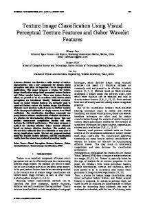
and Ström for detailed information [PS05]), and the planar mode was compressed using least squares fitting. The diagram in Figure 7 shows the quality for the entire test set. For each mipmap size, the MSE score has been average over all images in the set, and then the aggregate PSNR score for the test set is calculated using Equation 1. As can be seen in the the diagram, ETC2 outperforms the second best scheme (S3TC/DXTC) with a margin of between 0.82 dB and 1.3 dB. As a rule of thumb, a difference of about 0.25 dB is visible, so a difference of 0.82 is clearly visible. Figure 9 show some examples of compressed images. Images for S3TC/DXTC, ETC, ETC2 are provided as well as the original and a block map that tells which mode is used per block in ETC2. All blue would mean that the image would be exactly the same as ETC. Note how sharp color transitions that previously gave rise to block artifacts are handled much better (first row). Smooth color transitions work very well due to the planar mode, whereas they are often grainy or blocky in S3TC/DXTC and ETC (second row). Since the method is backward compatible, areas that were compressed well with ETC are left the same or slightly improved (third row). For blurry areas, the planar mode is almost exclusively used, and the result is a huge improvement over S3TC/DXTC and ETC (fourth row). Colored text on colored background is most often greatly improved (fifth row), but sometimes remains problematic (sixth row).
Thanks to Tomas Akenine-Möller who spawned the idea idea to try redundant bit combinations for ETC. Thanks also to Eric Fausett, Eisaku Ohbuchi and DMP for permission to publish test images.
References [AMN03] A ILA T., M IETTINEN V., N ORDLUND P.: Delay Streams for Graphics Hardware. ACM Transactions on Graphics, 22, 3 (2003), 792–800. [BAC96] B EERS A., AGRAWALA M., C HADDA N.: Rendering from Compressed Textures. In Proceedings of SIGGRAPH (1996), pp. 373–378. [CDF∗ 86] C AMPBELL G., D E FANTI T. A., F REDERIK SEN J., J OYCE S. A., L ESKE L. A., L INDBERG J. A., S ANDIN D. J.: Two Bit/Pixel Full Color Encoding. In Proceedings of SIGGRAPH (1986), vol. 22, pp. 215–223. [DM79] D ELP E., M ITCHELL O.: Image Compression using Block Truncation Coding. IEEE Transactions on Communications 2, 9 (1979), 1335–1342. [Fen03] F ENNEY S.: Texture Compression using LowFrequency Signal Modulation. In Graphics Hardware (2003), ACM Press, pp. 84–91. [IM06] I NADA T., M C C OOL M.: Compressed Lossless Texture Representation and Caching. In Graphics Hardware (2006), ACM Press, pp. 111–120. [INH99] I OURCHA K., NAYAK K., H ONG Z.: System and Method for Fixed-Rate Block-based Image Compression with Inferred Pixels Values. In US Patent 5,956,431 (1999).
34 ETC2 S3TC/DXTC ETC ATI−TC
33
Acknowledgements
32 31
[KSKS96] K NITTEL G., S CHILLING A., K UGLER A., S TRASSER W.: Hardware for Superior Texture Performance. Computers & Graphics 20, 4 (July 1996), 475– 481.
PSNR (dB)
30 29 28 27
[MAMS06] M UNKBERG J., A KENINE -M ÖLLER T., S TRÖM J.: High-Quality Normal Map Compression. In Proceedings of Graphics Hardware 2006 (2006), pp. 95– 101.
26 25 24
8
16
32
64 size
128
256
512
Figure 7: PSNR scores averaged over the entire test set of 64 images, for different mipmap resolutions.
8. Conclusion We have presented an extension of ETC called ETC2. By using invalid bit sequences, we are able to fit three new modes to the codec, while keeping exactly the same bit budget. Since we wanted to preserve backwards compatibility, this work had to be incremental by definition, but we think the performance increase of 0.82 dB is substantial, especially since it improves problematic blocks.
[PS05] P ETTERSSON M., S TRÖM J.: Texture Compression: THUMB — Two Hues Using Modified Brightness. In Proceedings of Sigrad, Lund (2005), pp. 7–12. [SAM04] S TRÖM J., A KENINE -M ÖLLER T.: PACKMAN: Texture Compression for Mobile Phones. In Sketches program at SIGGRAPH (2004). [SAM05] S TRÖM J., A KENINE -M ÖLLER T.: iPACKMAN: High Quality, Low Complexity Texture Compression for Mobile Phones. In Graphics Hardware (2005), ACM Press, pp. 63–70. [TK96] T ORBORG J., K AJIYA J. T.: Talisman: commodity realtime 3D graphics for the PC. In International Conference on Computer Graphics and Interactive Techniques (1996), ACM Press, pp. 353–363. c Association for Computing Machinery, Inc. 2007.
Jacob Ström and Martin Pettersson / ETC2: Texture Compression using Invalid Combinations
Figure 8: Left: Original. Right: ETC. The limitation of having only one chrominance per subblock gives rise to block artifacts.
Legend of blocks for the ETC2 mode differential or individual
original
59 bit T-mode
S3TC/DXTC
58 bit H-mode
57 bit planar mode
ETC
ETC2
block map
Figure 9: Left to right: Original image, original cutout, S3TC/DXTC, ETC, ETC2 and a block map, which shows what modes are used in ETC2. First row: In ETC, sharp color transitions give rise to block artifacts, whereas they are greatly reduced in ETC2. Second row: Smooth color transitions work very well with ETC2, whereas they are often grainy or blocky with S3TC/DXTC and ETC. Third row: For areas where ETC works well, the quality is preserved or slightly improved. Fourth row: For blurry parts, the planar mode is almost always selected, and the quality difference against S3TC/DXTC and ETC2 is huge. Fifth and sixth rows: Colored text on colored background is often greatly improved (fifth row), but sometimes problems remain (sixth row).
c Association for Computing Machinery, Inc. 2007.