Evaluating Multicore Architectures for Application in High Assurance Systems Ryan Bradetich, Paul Oman, Jim Alves-Foss, and Theora Rice Center for Secure and Dependable Systems University of Idaho Contact:
[email protected], {oman, jimaf}@uidaho.edu,
[email protected]
Abstract Multiple Independent Levels of Security (MILS) systems require the ability to cleanly isolate various processes from each other in order to ascertain separation of differing data classification levels. This has been traditionally performed using a four layer approach: Applications, Middle-ware, Separation Kernel, and Hardware. This paper introduces a framework for evaluating information flows in multicore architectures and then showing how these information flows may be mapped to the Separation Kernel layer.
1 Background Advances in microprocessor manufacturing technologies and limitations of memory access speeds have led to the development of multicore processors. With multiple execution units within a single chip (or package), the expectation is that applications can better overcome memory and I/O latencies through parallel processing of independent processes. While this new architectural approach has proven to be advantageous and popular, it has also brought some interesting new security concerns. Of particular interest is how these security concerns might be managed so that these multicore processors might be effectively deployed in high assurance environments and situations. In a traditional Multi-Level Security (MLS) system, the operating system, run-time executive, or security kernel has control over the system resources, and is able to manage them in a way that provides controls over unauthorized access and information flow. One way to use a multicore processor in a MLS environment is to separate applications of different security domains onto separate cores. This approach is similar to the popular idea of using virtualization to ensure isolation. However, just as with virtualization, this assumption of isolation may be optimistic: in a multicore processor, the different cores will have access to some shared resources, which may result in unforeseen security vulnerabilities. An alternative approach is to have a security monitor running in one core observing and controlling behavior in another. The University of Idaho's MILS approach has taken this later path by employing a separation kernel as the run-time executive, which implements time and space separation and controls information flows between partitions [1]. Both of these approaches are still subject to some degree of shared resources within the multicore process, possibly leading to covert channels or other security concerns. In this paper we introduce a framework for evaluating the information flow within multicore architectures so that vulnerabilities and covert channels can be identified and mitigated. We start with an overview of four relatively recent multicore architectures, then introduce a sketch of our framework, and apply that framework to one of the example architectures.
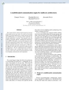
2 Multicore Architectures Prior to 2003, the traditional methods for boosting processor performance were to increase the clock frequency, add high-speed, on chip cache, and optimize instructions [2]. These traditional methods worked for many years until physical issues limited the processor clock frequency to around 4 GHz in 2003. Although physical issues limited the processor clock frequency, the transistor still continues to shrink. Multicore architectures capitalize on smaller process sizes and increased transistor counts to provide multiple execution units on a single chip. The following four multicore processor architectures illustrate the variety and complexity of multicore architectures. 2.1 Cell Broadband Engine Architecture (CBEA) The CBEA processor application environment ranges from gaming consoles (e.g., PlayStation 3) to high performance supercomputing (e.g., the Roadrunner super computer at Los Alamos National Laboratory). The CBEA provides the Power Processing Element (PPE) as a single, general purpose Simultaneous Multi-threading (SMT) processor core, with two logical cores [3]. The CBEA also provides Synergistic Processor Element (SPE) cores (typically eight) which are designed for computationally intensive tasks. These specialized cores implement a different instruction set from the general purpose SMT core. Each specialized core has its own local memory store. Each CBEA component is connected via four one-way buses configured in a ring. Two of these rings run clockwise while the other two rings run counter-clockwise. The CBEA uses Direct Memory Access (DMA) to move data between the CBEA Components. The CBEA provides a hardware security architecture where one or more of the specialized cores can be put into a secure processing mode. When in this secure processing mode, the hardware isolates the core so no other core, operating system, or hypervisor can interrogate the internal state of the isolated core. Figure 1 provides a block diagram of the CBEA processor.
Figure 1: CBEA Processor
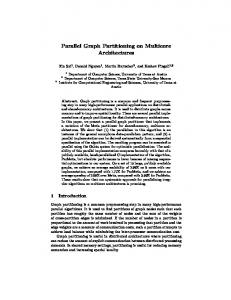
2.2 Tilera TILE64 The TILE64 processor is targeted towards advanced network embedded applications such as: In-Line deep packet inspection, Network Security Appliances, and Network Monitoring. The TILE64 multicore processor contains 64 independent, general purpose cores [4]. Each core has its own private Level 1 (L1) and Level 2 (L2) cache as well as a distributed Level 3 (L3) virtual cache. The cores are connected using non-blocking switches in an intelligent mesh (iMesh). The iMesh provide extremely low-latency and high-bandwidth communication between the cores, memory, and other I/O. Each core is capable of running an independent operating system, or can be grouped to run a Symmetric Multiprocessing (SMP) operating system. In addition to the processing cores, this processor also includes memory and I/O controllers. Figure 2 provides a block diagram of the TILE64 processor.
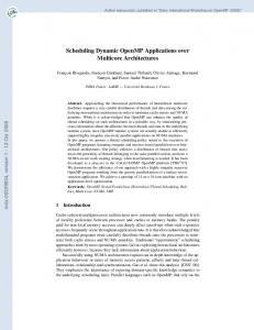
Figure 2: TILE64 Processor 2.3 Intel Core i7 The Intel Core i7 processor is targeted towards general purpose computing. Multicore performance improvements are achieved by: (1) replicating the core execution unit, (2) adding additional processor instructions, and (3) improving the communication between the cores. Two major changes for the Core i7 architecture include the large shared L3 cache and the QuickPath interconnect bus which is used for inter-process communication [5]. Figure 3 provides the high-level block diagram of the Core i7 processor.
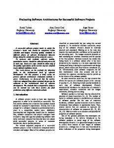
Figure 3: Intel Core i7 Processor 2.4 Freescale P4080 The Freescale Semiconductor QorIQ P4080 communications processor provides eight Power Architecture cores, each with integrated L1 and L2 caches [6]. The chip is intended for embedded systems and includes a variety of memory and I/O controllers. This processor supports a multi-megabyte shared L3 cache. Hardware provides acceleration for encryption, regular expression pattern matching, and Ethernet Packet Management. On-chip components are connected by the CoreNet coherency fabric which manages full cache coherency between the caches and point-to-point, concurrent connectivity between the hardware components. Figure 4 shows a block diagram of the P4080.
Figure 4: P4080 Processor 3 A Framework for Multicore Information Flow Analysis In the previous section, we introduced four processor architectures to illustrate the variety and complexity of multicore architectures. The complexity of multiple execution units along with hardware acceleration resources provides ample opportunity for covert channels and security vulnerabilities. Potential information flows inside the hardware must be evaluated as part of the security of the system.
This section introduces a framework for simplifying the analysis of multicore architectures into information flows, visible state, and safeguards. These information flows, visible states, and safeguards can then be mapped to the security policy. The framework has three distinct steps or stages: 1. Hardware component identification. 2. Information flows, safeguards, and component state analysis. 3. Security policy mapping. For illustration purposes, we now apply our framework to the Freescale P4080 multicore architecture described in Section 2.4. This paper is not intended to provide a full analysis of the P4080 multicore architecture using this framework, but intends to introduce the framework using the P4080 multicore architecture. 3.1 Hardware component identification The first step in the framework is to analyze the multicore architecture to identify and record all the major components. This component list provides a road map during the analysis, potentially identifies underdocumented resources, and provides an executive summary of the component the components analyzed during. For the purpose of this paper, we provide a partial analysis for the processor cores, CoreNet coherency fabric, and the frontside L3 cache. Figure 5 highlights the P4080 components briefly analyzed in this paper.
Figure 5: P4080 Modules 3.2 Information Flows, Safeguards, and Component State Analysis The second step in the framework is to analyze information flows and externally visible state for each component. To simplify the analysis of information flows and externally visible state, we introduce a new abstraction: the polyhedron. The polyhedron completely surrounds the component or group of components being analyzed, so any information entering, leaving, or passing through must breach one of the polyhedron surfaces. Each component may only exist in a single polyhedron. The abstract polyhedron concept also has a color. The color itself is arbitrary and is intended as a metaphor to represent the externally visible state for the component(s).
Everything inside the polyhedron is considered to run in a system high mode. This means all data inside the polyhedron is treated as a single data classification and all data access requests inside the polyhedron are permitted. Figure 6 illustrates the polyhedron abstraction.
Figure 6: Polyhedron Abstraction The polyhedron abstraction allows us to simplify the information flow analysis. Any information flow which does not breach any the polyhedron or does not modify the externally visible state (i.e., the polyhedron color) can be ignored. Figure 6 illustrates three information flows: A, B, and C. Information flow A originates externally and terminates inside the polyhedron abstraction. Information flow B originates inside the polyhedron abstraction and terminates somewhere outside the polyhedron abstraction. Information flow C passes through the polyhedron abstraction, but originates and terminates external to the polyhedron abstraction. A safeguard is any mechanism that can be tuned to control the externally visible state and/or information flows entering, leaving, or passing through the polyhedron abstraction. To improve the reuse and scalability of the security analysis, the goal is to minimize the amount of “space” inside the polyhedron abstraction while maximizing the safeguards controls on the information flows. The next sections apply step #2 of the framework to the processor cores, CoreNet coherency fabric, and the frontside L3 cache components. 3.2.1 Processor cores The P4080 multicore architecture provides eight general purpose processing cores. These processing cores are configurable to run as individual stand alone processing cores, one big Symmetric MultiProcessing (SMP) system, or any other combination. Each processing core is composed of registers, private L1 and private L2 caches, and a super-scalar instruction execution unit. To provide the maximum scalability and reuse, each processor core is analyzed as an independent system high module (i.e., in its own polyhedron). The primary purpose of each processor core is to execute processor instructions. The PowerPC instructions set for the e500mc processor core can be categorized into the following categories: integer and floating point instructions, load and store instructions, processor and flow control instructions, and memory synchronization and control instructions. The majority of the e500mc processor instructions are integer and floating point instructions, most of which do not create (or cause) information flows by crossing a polyhedron surface. However, a limited number of these instructions may cause an external state change by generating an exception (e.g.,
division by zero). These identified instructions should be reviewed in greater detail during the analysis process. The remaining e500mc processor instructions typically cause an information flow by either breaching the abstract polyhedron or changing the externally visible state of the processor. For example, the load and store instructions may breach the abstract polyhedron by reading or updating memory mappable address space. Since most of the P4080 components are memory mappable, the information flows from each processing core to all of the other hardware components is significant. Each e500mc processor core provides a Memory Management Unit (MMU) which can restrict which memory addresses are visible to the processing core. The e500mc MMU serves as a safeguard, that when configured properly, can be used to restrict information flows from each core. Other e500mc processor instructions (e.g., wait) do not breach the abstract polyhedron, but do alter the externally visible state of the processor core by stopping the fetching and the execution of instructions until an external interrupt is received. For this example, we could say the e500mc processor core has three externally visible states: fetching instructions (green), an exception state (yellow), or a wait state (red). When the wait instruction is executed, the abstract polyhedron color would turn from green to red. After the interrupt was received to cause the processor core to resume fetching and executing instructions, the abstract polyhedron color would turn from red back to green. In addition processor instructions, a full analysis of the processor cores must include: virtualization and virtual machine escapes, secure boot mode and the trust architecture, interrupts and exceptions, L1 and L2 caches, memory management units, and processor debug modes. That detailed analysis is beyond the scope of this paper. 3.2.2 CoreNet Coherency Fabric The CoreNet coherency fabric serves as a central interconnect for processor cores, platform-level caches, memory subsystems, peripheral devices, and I/O host bridges [7]. The main purpose of the CoreNet coherency fabric is to provide the communication channel to move data from the source component to the destination component. This component has information flows to pretty much everything in the system. There are two safeguards that are able to restrict information flows through the CoreNet coherency fabric: the processor core’s MMU and the Peripheral Access Management Unit (PAMU). The processor core information flows are restricted by their own MMUs. Each non-CPU Direct Memory Access (DMA) master is assigned a unique Logical I/O Device Number (LIODN) by the hypervisor for identification. The PAMU provides access controls to prevent non-CPU DMA masters from accessing memory which were not explicitly granted access permission. In addition to the normal operating mode, each PAMU can be configured into a bypass mode that changes the behavior of how the PAMU works. Setting the PAMU in bypass mode would effectively change the “color” of the PAMU polyhedron from black to red. The PAMU is also able to generate interrupts for two conditions: (1) Access violation error, and (2) PAMU operation error. These conditions would also need to be modeled by the PAMU polyhedron abstraction.
3.2.3 Frontside L3 Cache (CoreNet Platform Cache) The frontside L3 cache (a.k.a., CoreNet platform cache) connects the memory controllers to the CoreNet coherency fabric. The CoreNet platform cache can be configured in one or more of the following modes: (1) a general purpose write-back cache, (2) an I/O stash, or (3) a memory mapped SRAM [7]. When the CoreNet platform cache has a backing store (i.e., configured in the general-purpose write-back cache mode or the I/O stash mode), the CoreNet platform cache is only able to cache address ranges present in the memory controller behind it. Each mode defines the allowable information flows and the L3 cache “color.” The CoreNet platform cache provides no ability to restrict information flows entering, leaving, or through itself, it does provide a safeguard for the cache replacement policy. When a cache miss occurs, the CoreNet platform will look up by partition, action, and way to determine the appropriate cache replacement policy. The CoreNet platform cache can also be disabled, thus defining two externally visible states: enabled (green) and disabled (black). 3.3 Security Policy Mapping The final step of the framework is to map the separation kernel layer (i.e., security policy) to the hardware layer. The polyhedron abstraction simplifies this process by identifying which information flows are possible, how these flows are generated, and what safeguards are in place to restrict them. A separation kernel security policy is often defined as partitions with directional arrows representing information flows. In addition to the directional information flows, the whitespace (or lack of information flows) is also important to the security policy. Ideally, a one-to-one mapping between the polyhedron abstractions and the separation kernel partitions would exist. When the one-to-one mapping does not exist, the hardware is not able to enforce the separation kernel security policy and a compensating control will need to be considered. To illustrate how the security policy is mappable to the hardware layer, we introduce an example security policy and map it to the P4080 hardware layer. Figure 7 provides a simple security policy where: Core 0 is permitted two way communication with Memory Region 1 Core 1 is permitted two way communication with Memory Region 0. All communication between Core 0 and Core 1 is prohibited. All communication between Memory Region 0 and Memory Region1 is prohibited.
Figure 7: Example Security Policy
In Section 3.2.2, we identified each processor core executes instructions which have potential information flows to the entire memory mapped address space. We also identified that each processor core provides a MMU that is able to provide access controls for the memory mapped address range. To implement the security policy on the P4080 hardware, the separation kernel layer would need to properly configure the MMUs for both processor core 0 and processor core 1 to the appropriate memory regions.
Figure 8 shows the restricted information flows on the P4080 architecture after the security policy has been implemented.
Figure 8: Example Hardware Information Flows
Additional information flows may exist due to the externally visible state (i.e., the polyhedron color) of each processing core. These information flows may either be presented as storage or timing covert communication channels. Due to the missing P4080 architecture details not presented in this paper, the analysis of mapping the externally visible state to the security policy is beyond the scope of this paper. The identification of relevant information flows is an important benefit for using the polyhedron abstraction model when analyzing new multicore architectures. The relevant information flows provide a road map which allows implementers to better design experiments and test cases to ensure the separation kernel always permits authorized information flows and prohibits unauthorized information flows.
4 Conclusions This paper describes the increasing complexity of multicore architectures and the need for analyzing those architectures for information flow vulnerabilities. We showcase four multicore architectures to illustrate how the processor architecture landscape is varied and changing. To address the increasing complexity in the processor landscape, we then introduce a framework for abstracting hardware into information flows, safeguards, and externally visible state. In our work at the Center for Secure and Dependable Systems we have applied the framework to the CBEA, Intel Core i7, and the Freescale P4080. In this paper we provided a sketch showing how to apply the framework to the P4080. It was not meant to be a complete analysis but, rather, a glimpse of how the framework addresses the variety and complexity of subsystems now found within multicore architectures.
5 Acknowledgement This material is based on research partially sponsored by the Air Force Research Laboratory under agreement number FA8750-10-2-0134 and National Science Foundation under contract DUE-0621348.
The U.S. Government is authorized to reproduce and distribute reprints for Governmental purposes notwithstanding any copyright notation thereon. The views and conclusions contained herein are those of the authors and should not be interpreted as necessarily representing the official policies or endorsements, either expressed or implied, of the Air Force Research Laboratory or the U.S. Government.
6 References [1] J. Alves-Foss}, W. S. Harrison, P. Oman and C. Taylor. “The MILS Architecture for High Assurance Embedded Systems”, International Journal of Embedded Systems, 2(3/4):239-247, 2006. [2] H. Sutter, “The free lunch is over: A fundamental turn toward concurrency in software,” Dr. Dobb's Journal, Vol. 30(3), Mar. 2005. http://www.gotw.ca/publications/concurrency-ddj.htm. [3] S. Keckler, K. Olukotun, & H. P. Hofstee, Multicore Processors and Systems, New York, NY: Springer, 2009. [4] Tilera, TILE64 Processor Product Brief, http://www.tilera.com/sites/default/files/productbriefs/PB010_TILE64_Processor_A_v4.pdf; accessed 09-Sept-2011. [5] Intel, An Introduction to the Intel QuickPath Interconnect, http://www.intel.com/technology/quickpath/introduction.pdf; accessed 09-Sept-2011. [6] Freescale Semiconductor, P4 Series - P4080 Multicore Processor, http://cache.freescale.com/files/netcomm/doc/fact_sheet/QorIQ_P4080.pdf?fpsp=1; accessed 09Sept-2011. [7] Freescale Semiconductor, P4080 QorIQ Integrated Multicore Communication Processor Family Reference Manual, Doc. #P4080RM, Rev. 0, April 2011