software analysis and design languages such as the Unified. Modeling Language (UML) [1] or the Specification and De- scription Language (SDL) [2] and their ...
Evaluating UML Extensions for Modeling Real-time Systems Lutz Bichler, Ansgar Radermacher, Andreas Schürr University of the German Federal Armed Forces Munich 85577 Neubiberg, Germany Email:[lutz ansgar schuerr]@informatik.unibw-muenchen.de Abstract Rather recently object-oriented modeling languages, tools, and methods attract the interest of embedded (realtime) system developers. This is especially true if embedded (real-time) system software has to cooperate with interactive multimedia software, as it is more and more the case in automotive systems. It is still an open question whether and how the standard OO modeling language UML and its accompanying tools have to be adapted to the regarded application domain. To contribute useful input for this discussion we evaluated two popular CASE-tools, I-Logix Rhapsody® and Rational Rose/RT® , that implement real-time UML extensions, by developing rapid prototypes of an air condition controller.
1. Introduction Embedded system software plays a role of rapidly increasing importance for the automotive industry. Wellknown safety increasing functions like ABS (Anti-lock Brake System), ETC (Electronic Track Control) and ESP (Electronic Stability Program) are implemented in software. Furthermore, an exploding number of comfort functions and telematic functions are realized in software. They are accompanied by more and more sophisticated user interfaces, thereby blurring the distinction between traditional embedded system software with rather specific input and output devices on the one hand and state-of-the-art PC software user interfaces, which rely on keyboard, mouse and (touch) screen as all-purpose input/output devices on the other hand. Therefore, the time is ripe for software engineering techniques and tools, which support the integrated development of traditional embedded system software and software components with complex (multimedia) user interfaces. Such software engineering techniques and tools should rely on
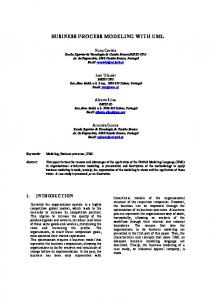
the object-oriented (OO) software paradigm for the following reasons: (1) OO Programming languages are nowadays more or less exclusively used for the construction of interactive user interfaces, (2) many recently developed standard software analysis and design languages such as the Unified Modeling Language (UML) [1] or the Specification and Description Language (SDL) [2] and their accompanying tools rely on the OO paradigm and (3) well-known software engineering principles as information hiding by data abstraction and reuse of software components by inheritance and genericity are supported. In the following we concentrate on the usage of UML dialects for modeling embedded real-time systems. UML is a visual modeling language for specifying, visualizing, constructing and documenting software systems and business processes. It was created in 1994 as fusion of the objectoriented methods Booch [3], OMT [4] and OOSE [5]. The UML specification defines a formal Object-oriented Analysis&Design metamodel, which includes diagram types for static, behavioral, usage, and architectural aspects of software systems. Different to its predecessors, the UML specification only specifies syntax and semantics of its notation, but does not determine how to apply its elements within a development process. Therefore, serveral different modeling methods ([6],[7], [8], [9]) use the UML notation and additionally consider domain specific details. While UML is well-suited for modeling software systems in general, it lacks support for some aspects important to embedded real-time systems, e.g. modeling of timing constraints, signals, and independent components. Therefore, different proposals to extend the UML for modeling real-time systems have been made. This is depicted in figure 1. The Object Management Group (OMG) proposes to extend the UML by building UML “profiles” [10] that contain the needed extensions. But this extension mechanism is currently not part of the standard and it is still discussed how to realize it [11]. In parallel the leading CASE tool vendors implement proprietary extensions to the UML. Rational and Telelogic adapt UML for modeling embedded
UML/RT Profile (OMG) ?
UML/Realtime Rational Rose/RT
?
?
"Pure" UML I-Logix Rhapsody
UML+SDL Telelogic Tau
Finally we summarize our experiences, present a short table showing ratings of the criteria for Rhapsody® and Rose/RT® and outline the area of our research activites in the area of modeling embedded real-time systems in Section 5.
2 The Running Example: An Air Condition
ROOM (ObjecTime)
UML (OMG-Standard)
SDL (ITU-T-Standard)
Figure 1. UML and dialects real-time systems by combining it with the modeling languages from the real-time (ROOM) and telecommunication domains (SDL), while I-Logix stays with Standard-UML, but provides a very powerful implementation of statecharts. This paper reflects our experiences with the OO development of embedded (soft) real-time system software using the two popular UML CASE tools Rhapsody® and Rose/RT® . We will first introduce our running example in Section 2, the heating system within an air condition controller for a car. Using this example we will demonstrate in Section 3 that Realtime UML as supported by the CASE tool Rhapsody® [8] encourages a modeling style, where it is difficult to isolate reusable software components both on the modeling as well as on the implementation level. Afterwards, we will compare the presented Realtime UML model with two different UML/Realtime models, which make use of the component-oriented UML extensions supported by the CASE tool Rose/RT® [9] in Section 4. The first presented UML/Realtime model is a naive translation of the previously developed Rhapsody® model. Despite of the now enforced component-oriented modeling style it still fails to isolate different functional aspects of the air condition controller such as its “normal” behavior and its “exception handling” behavior from each other. This deficiency is solved by the second model, which combines UML/Realtime components (capsules) with a pipe/filteroriented modeling style. While modeling the example we concentrated on evaluating the following criteria: ease of use, conformity to the UML standard [1], supported modeling styles, the ability to express different types of behaviour, and support for simulation, definition of test cases and verification. By evaluating the modeling style criterion we mean rating the suitability of the tools to model in an object-oriented and/or component-oriented style and evaluating the behaviour criterion the level of support for modeling event-driven, timedriven and data-driven behaviour.
The controlling unit for an air condition is a sufficiently complex embedded system for the evaluation of the pros and cons of different software development methods and their accompanying CASE tools. An air condition has to stabilize temperature and humidity within a closed room. Its main components are a cooling system, a heating system, a humidity regulator and a fan. In our (simplified) example we assume that our air condition consists of a thermosthat, a temperature sensor, a heating system and a cooling system. The heating system consists of the standard heating system and an additional heating system that is used to shorten the time needed to increase the temperature within the car after starting. Due to space limitations we cannot present the complete models which realize all functions of the air condition controller here. Therefore, we will focus our interest onto one specific part of the air condition controller, its heating system subcontroller. Therefore, its requirements specification has about the following form: 1. The heating system consists of two heating subsystems and has two heating levels: level1 and level2. In level1 only the standard heating system is active, while in level2 the additional heating system is active, too. 2. An incoming temp event changes the heating system’s status from off to level1 and from start to level 2. 3. The heating system automatically changes its status from level2 to level1 after 10 minutes. 4. The heating system automatically changes its status from start to off after 10 minutes. 5. A number of exceptions (low/high voltage, ignition key in status “cold”, ����� ) immediately cause temporary deactivations of the heating system. 6. As soon as there are no more exceptions, the heating system continues operating on the selected level. 7. The heating system is switched off if the ignition key stays in status “cold” for more than 5 min. or if it is removed.
In the following we will present the three different models of the heating controller which make use of the different UML dialects implemented by Rhapsody® and Rose/RT® . In all cases, we will specify the regular behavior of the heating system, its treatment of so-called low-level exceptions (causing temporary deactivations), and its treatment of socalled high-level exceptions (causing a transition to status off) as separate exchangeable submodels.
3 The Realtime UML Model of the Heating System ®
I-Logix’s CASE-tool Rhapsody implements an UML dialect called Realtime UML, which contains Object-Model diagrams for modeling the static system structure. Figure 2 depicts a model of the air condition controller. The composite class AirConditionControl has composition relationships to the classes TemperatureSensor, Thermostat, CoolingSystem and HeatingSystem. Different to other class diagrams this is represented by drawing the compartments within the area of the composite class. Additionally, figure 2 shows that the classes CoolingSystem and HeatingSystem send messages to each other, in order to inform about their states (on, off), because these two should not be active at the same time. Unfortunately, figure 2 does not provide informations about the communication between the composite class and its compartments. As long as the context of the diagram is missing, it also does not show relationships to the outer world. Therefore, some important parts of the air condition control’s functionality are hidden as long as the context is not depicted in the same diagram, which complicates the development of independent software components. The outstanding property of Realtime UML is its rather powerful variant of Harel’s state charts [8]. In contrast to many other UML CASE-tools it supports and-states, which are states with several concurrently executed subcharts. Therefore, it is quite tempting to realize the heating system subcontroller as one object with a complex state chart. This state chart is depicted in Figure 3. It consists of one and-state with three parallel subcharts. Thus the system is in three states at the same time, one per subchart. These subcharts specify the regular behavior of the controller as well as its treatment of high- and low-priority exceptions. The regular behavior subchart consists of four states start, level1, level2, and off. Initially the system is in the state start. An incoming temp event causes a transition to level2 if state start is active and a transition to state level1 if state off is active. Furthermore, the subchart contains transitions of the form tm(t). These transitions fire whenever their source state is the active state for t milliseconds. They realize the required transitions from level2 to level1 after 10 min. and from start
AirConditionControl
TemperatureSensor
Thermosthat
actualTemperature
desiredTemperature
getActualTemperature()
setDesiredTemperature(Temp t)
CoolingSystem
Dia(PDia pd) Volt(PVolt pv) KL(PKL kl) Door(PDoor pd)
HeatingSystem
Volt(PVolt pv) KL(PKL kl) Motor(PBlock pb) in(PHeatingControl hc)
Figure 2. Rhapsody class diagram of air condition control
to off after 10 min. Incoming off events cause transitions to the state off if the system is in state level1 or level2. The next subchart for high priority exceptions has three states: okayHPrio is active if there is no high priority exception, waitHPrio is active for 5 min. after the recognition of a high priority exception, and offHPrio is active whenever the heating system has to be switched off completely. Currently, an event ignitionKeyCold signals the beginning of a high priority exception, whereas the event ignitionKeyRadio signals its end. Furthermore, the event ignitionKeyOff (raised by the removal of the car’s ignition key) causes a transition to the state offHPrio, the subchart’s initial state. The last parallel subchart of figure 3 handles all sorts of low priority exceptions simultaneously. It contains the initial state okayLPrio, which is active when no exceptions are signaled; its second state blockedLPrio is active if at least one exception has been recognized. It uses a local attribute (variable) i for keeping track of the number of currently active exceptions. The still missing coordination of the three subcharts is realized as follows as part of the “regular behavior” subchart: guards of the form [!(IS_IN(offHPrio)] check whether the heating controller is not in state offHPrio. They prohibit transitions from state off to state level1 or level2 after the heating system has been switched off by the recognition of a high priority exception and before its reactivation by the ignition key’s signal ignitionKeyRadio. Transitions which have the guard IS_IN(offHPrio) as their label guarantee that the heating system is indeed switched off if required.
HeatingSystem
level1 blocked>
RegularBehavior tm(600000)
start>
C
[IS_IN(offHPrio)] temp[!(IS_IN(offHPrio))]
off
level2...
[!(IS_IN(okayLPrio)) ]
temp[!(IS_IN(offHPrio))] off [IS_IN(offHPrio)] level1...
tm(600000)
HighPrioExceptions ignitionKeyRadio
[else]
off>
ignitionKeyOff
offHPrio
[IS_IN(okayLPrio)]
tm(5000)
okayHPrio
ignitionKeyCold
okay> waitHPrio
ignitionKeyRadio
[IS_IN(okayLPrio)]
LowPrioExceptions OnException/i++;
OnException/i=1; blockedLPrio
okayLPrio
OffException[i==1]/i=0;
OffException[i>1]/i--;
Figure 3. Statechart for the heating system controller
Temporary deactivations of the heating system caused by low priority exceptions have to be handled differently. They may not fire transitions which leave state level1 or level2 for the following reason: if we would leave and later on reenter state level2 then we would terminate and restart the associated 10 min. timer. Therefore, we have to realize level2 as complex or-state of the same form (see figure 4 for the level2 state chart). Whenever leveli is entered, its substate okay is activated if the low priority subchart is in state okayLPrio. Otherwise its substate blocked is activated. This is expressed by using condition connectors together with the guards [IS_IN(okayLPrio)] and [else]. Additional transitions guarantee that the or-state’s active substate changes appropriately, whenever the heating controller object enters or leaves its substate okayLPrio1. The presented Realtime UML model of the heating system controller is rather compact and realizes all features required in Section 2. It even specifies the different functional aspects of the controller as separate subcharts. Nevertheless, the constructed state chart has to be criticized from a software engineer’s point of view. There are no well-defined interfaces between the different subcharts of the parallel and-state. Therefore, it would be unnecessarily difficult to modify the exception handling behavior of the controller. Any modification of one of the three subcharts requires a 1 The actions which activate and deactivate indeed the heating system have been omitted. They should be added as entry actions of the states off, blocked, and okay, respectively
Figure 4. Level2 state chart of the heating controller model
careful inspection of all IS_IN predicates of its other subchart. Thus Rhapsody® ’s main advantage of having a very powerful statechart implementation can become it’s biggest disadvantage at the same time, because it encourages a modeling style that often leads to models with a small number of objects with complex behaviour. Such objects are usally not very well suited for building systems which are easy to understand, change, and maintain. Additionally Rhapsody® does not support a component-oriented modeling style and does not show the communciation with the system context without having the context in the same diagram, because classes usally reference other classes directly. This again does not facilitate the work of designing “good” software systems.
4 The UML/Realtime Model of the Heating System UMl/Realtime [9], the UML dialect of the CASE tool Rational Rose/RT® [12], enforces a rather different modeling style than Rhapsody for the following two reasons: (1) it supports a state chart variant without parallel and-states and without any means to fire transitions whenever a specified state becomes active or inactive. (2) It offers its users a new diagram type inherited from the real-time object-oriented modeling language ROOM [13]. These so-called structure diagrams, introduced as a special variant of UML’s collaboration diagrams, support a component-oriented modeling style. Structure diagrams contain a new type of entities, the socalled capsules. These capsules exchange a well-defined set of signals via some explicitly depicted connections. Figure 5 shows a simplified structure diagram for our air condi-
tion controller. It shows the decomposition of the air condition control into the five capsules temperatureSensor, thermostat, heatingSystem, coolingSystem and mainController. The capsule temperatureSensor is an instance of class TemperatureSensor, which is shown by ”/heatingSystem : HeatingSystem”. Correspondingly, temperatureSensor is an instance of class TemperatureSensor, thermostat of class Thermostat and so on. We omitted the (hardware) context in order to improve the readability of the diagram. In the ”real”model we have additional wrapper classes for the hardware components that influence the function of the air condition, e.g. for ignition key and door.
squares, e.g. the in-port of capsule controller in figure 6 is connected to the outside of the heating system as well as to the high capsule. Kl15off,Kl15cold KL15radio,KL15on
temp, off
in in
out / high cIgnitionKey : ExceptionsH
cIgnitionKey
/ controller Block : ExtendedHeatingController
cIgnitionKey
ok, low, high
out / low : ExceptionsL cVolt
cVolt
on, off
Block temp, off
cDoor
cIgnitionKey
/ temperatureSensor : TemperatureSensor
/ thermostat : Thermostat
actualTemperature
desiredTemperature
cDoor
actualTemperature
cIgnitionKey
cVolt
desiredTemperature
/ mainController : Controller
cVolt increaseTemperature increaseTemperature
cIgnitionKey
cVolt
/ heatingSystem : HeatingSystem
Figure 6. Structure diagram for the heating system control
decreaseTemperature decreaseTemperature
/ coolingSystem : CoolingSystem
out
Figure 5. Structure diagram of the air condition control Any capsule has a number of ports, which may be used to attach a connection to a port of a related capsule. Each port has an assigned protocol definition. Protocol definitions enumerate the signals which can be exchanged through ports and can contain two different kinds of signals, inand out-signals. Normal ports—depicted as filled black squares—receive the in-signals and send the out-signals of their associated protocol definitions. Conjugated ports— depicted as filled white squares—receive the out-signals and send the in-signals of their associated protocol definitions. Connections are possible, if a normal and conjugated port have the same assigned protocol. An example are the Block ports of the controller- and low- capsules in figure 6. The normal Block port of capsule low is able to send the signals on and off and the conjugated Block port of capsule controller is able to receive them. Capsules can have ports that are connected to more than one port with the same associated protocol at the same time. This is depicted by several overlapping (black or white)
Because Rose/RT® does not support state charts with parallel AND-states like Rhapsody, we have to split the model on the structural level. Thus, we created a structure diagram with three capsules. One capsule realizes the regular behaviour of the heating system and the two other the two levels of exception handling. The resulting model is depicted in figure 6. It shows very clearly that the heating system control has to process incoming (exception raising) signals from the ignition key (port cIgnitionKey) and the battery (port cVolt). It also receives the temperature change events temp and off via the port with name in. Each capsule has a corresponding statechart, which realizes its behaviour. The regular behavior statechart (9) consists of four states start, level1, level2, and off. An incoming temp event causes a transition to level1 if state off or level2 is active and to level2 if state start is active. Furthermore, the subchart contains transitions of the form tm(t), which are depicted by the labels after10min. These transitions fire whenever their source state is the active state for t milliseconds. They realize the required transitions from start to off and from level2 to level1 after 10 min. The subchart’s initial state is start. Insofar the statechart is exactly the same as the first statechart of figure 3. But instead of implicitly generated IS_IN(offHPrio state events it processes in.Off events generated by the ExceptionH capsule and instead of implicitly generated IS_IN(okayLPrio events it processes block.on|off events. Finally, the structure diagram shows that the ExtendedHeatingController
capsulet’s out port is used to control the actual heating heating elements of the air condition. The state charts of the two exception handling capsules have exactly the same form as in figure 3 with one one exception: explicit actions are added which send the needed signals to the ExtendedheatingController capsule. Figure 7 shows the class diagram corresponding to the structure diagram of figure 6. It repeats the fact that the complex capsule HeatingSystem consists of three subcapsules. In addition it reveals the fact that the ExtendedHeatingController is a BasicHeatingController with one additional port for blocking signals from capsule ExceptionsH (the already existing port in of the BasicHeatingController is used to accept the additional ”switch off”signals from capsule ExceptionsL).
BasicHeatingController
off start
temp
level2
KL Block low
off
off
temp
off
level1 after10min
Initial
off start
temp
high ExceptionsH
after10min
Figure 8. Statechart for the basic heating controller
HeatingSystem
KL Volt Motor in
in out
Initial
after10min
off
off
temp
off
if (counter==0) send "level2" else send off
if (counter==0) send "level1" else send off
level2
H*
counterPlus
level1 after10min H*
counterMinus
controller ExceptionsL ExtendedHeatingController
Block
Volt KL MotorState Block
Figure 7. Class diagram of the heating controller Using inheritance allows us to define first a capsule with the state chart shown in figure 8. This state chart realizes the regular behavior of the heating system without any extensions for exception handling purposes. In a second step we add the communication facilities by inheriting this state chart in the ExtendedHeatingController capsule and extending it appropriately. The resulting state chart is depicted in figure 9. It refines the two inherited states level1 and level2. If the system enters state level1, it sends a signal L1 through port out if and only if counter has the value 0. If the system enters state level2, it sends a signal L2 through port out. Furthermore, it adds two transitions counterPlus and counterMinus that increment/decrement the newly introduced counter. In this way, it is possible to separate the different functional aspects of the heating system controller. Nevertheless, we believe that the presented usage of inheritance for this purpose is a kind of ”trick programming”. Therefore, we developed another UML/Realtime model, which uses
Figure 9. State chart for the extended heating controller
a slightly different variant of the BasicHeatingController, which uses a pattern oriented modeling style. This resulting model is shown in figure 10. The central element of the model is the BasicHeatingController capsule. It understands the signals off and temp at its port in. Figure 8 depicts the associated statechart.It consists of the four states start, level1, level2, and off. An incoming off event causes a transition to off, if the states level1 or level2 are active. An incoming temp event causes a transition to state level1, if state off is active and a transition to level2, if state start is active. Furthermore, the statechart contains two transitions after10min. They realize the required transitions from level2 to level1 respectively from state start to state off after 10 minutes. The initial state of the statechart is start. The BasicHeatingController capsule is combined with two additional filter capsules, which are responsible for handling high and low level system exceptions, as it is depicted in figure 10. The first filter capsule belongs to the class SignalFilter. The associated statechart is equivalent to the high level exception handling statechart which is presented as second subchart in figure 3. Within the filter chain, it (1) forwards all incoming signals
in L1, L2, off
setBlock1 Initial
in
Block1
KL
normal
/ filterButtons : SignalFilter
on, off
out
L1, L2, off
if (block1 || block2) tmpSignal = off; else tmpSignal = inSignal;
dataSignal
in on, off
Motor
out
on, off
on, off
Volt
setBlock2 / controller : BasicHeatingController
Block1
Block2 Block3
L1, L2, off
in
/ filterOutput : DataFilter
if (tmpSignal != outSignal) { outSignal = tmpSignal; send outSignal; }
Figure 11. The statechart of DataFilter capsule for low level exceptions
L1, L2, off
out
out
Figure 10. An UML/Realtime model with pipe/filter pattern for the heating system
in state okayHPrio and waitHPrio, (2) produces one additional off signal, whenever it enters state offHPrio, and (3) consumes all incoming signals until it exits from state offHPrio. The statechart of the second filter of class DataFilter, shown in figure 11, is more interesting. It handles one separate boolean flag for each sort of exceptions. This solution still works properly if the number of received block� .On and block� .Off signals are not in balance (which happened quite often, when we tested the first versions of our air condition controller model). All signals received at port in are first stored in an internal attribute. The single state’s entry action is then responsible for (1) forwarding the received signal to the capsule’s out port if all boolean flags are false, (2) sending the signal off to the out port as soon as one of the boolean flags becomes true, and (3) to resend the most recently received signal if the last boolean flag changes its value back to false. This UML/Realtime model with a signal and a data filter capsule is robust against additional on and off signals received via its exception forwarding ports. It uses a ”pipe and filter”software construction style to combine different (reusable) behavioral aspects of one embedded system controller. Furthermore, all needed software components communicate with each other via well-defined interfaces only. The presented solution has in our opinion only one drawback2 : the transition and state entry actions of the data filter capsule are rather complex compared with the simple purpose they have to fulfill. 2 Please note that comparisons of different software models in this paper disregard the size and the efficiency of the generated code.
Summarizing, we found the following advantages and disadvantages of Rational Rose/RT® , while modeling our example. It nicely supports the modeling of independent components with clearly defined interfaces and therefore supports modeling of product-lines or similar products by first modeling the basic behavior and refining it afterwards. Unfortunately Rose/RT does not ”really”merge UML and ROOM elements, but demands a decision between UML’s classes with synchronous operations and ROOM’s capsules with asynchronous signals. Modeling of dataflows, e.g. logical conditions for deactivating functions is unnecessarily complex and difficult. Therefore, it is rather complex and time consuming to apply some methodic ways of modeling, like the ”pipe/filter”-pattern.
5 Summary Within this paper we described the modeling of an embedded system with soft real-time requirements with the CASE-tools I-Logix Rhapsody® and Rational Rose/RT® . Both tools implement parts of the Unified Modeling Language [1] and some additional features in order to enhance their suitability for modeling real-time systems. While Rhapsody® implements a powerful variant of the UML statecharts, Rose/RT® merges UML with the concepts of ROOM [13], which is a method for object-oriented modeling of real-time systems. In table 1 we present a number of evaluation criteria and our valuations for both tools. It can be seen from the table that the most important differences between Rhapsody® and Rose/RT® are: • Rose/RT® is well suited for component-oriented modeling, because it inherits the powerful method to refine/redefine interfaces, simple operations and statecharts from ROOM. Rhapsody® is not suited for component-oriented modeling because classes directly reference other classes.
Property
Rhapsody®
Rose/RT®
ease of use
+
0
standard conform
+
0
object-oriented
+
+
component-oriented
-
+ +
asynchronous signals
+
synchronous operations
+
0
event-driven
+
+
time-driven
0/+
0
data-driven
-
-
simulation
+
+
test definition
-
-
verification
-
-
Table 1. Comparison of Rhapsody® and Rose/RT®
• The modeling language implemented by Rhapsody® is a little easier to handle, mainly because it does not contain an additional diagram type, like Rose/RT® ’s structure diagrams. For the same reason Rhapsody’s modeling language is nearer to the UML standard.
[2] Jan Ellsberger, Dieter Hogrefe, and Amardeo Sarma, SDL: Formal Object-oriented Language for Communicating Systems, Prentice Hall, London, 1997. [3] Grady Booch, Object-Oriented Analysis and Design, Benjamin Cummings Series in Object-Oriented Software Engineering. Benjamin Cummings, Redwood City, CA, 1994. [4] James Rumbaugh, Michael Blaha, William Premerlani Frederick Eddy, and William Lorensen, ObjectOriented Modeling and Design, Prentice Hall, Englewood Cliffs, NJ, 1991. [5] Ivar Jacobson, Object-Oriented Software Engineering: A Use Case Driven Approach, Addison-Wesley, Reading, MA, fourth edition, 1994. [6] Philippe Kruchten, The Rational Unified Process, Addison Wesley, New York, 1998. [7] D.F. D’Souza and A.C. Wills, Objects, Components, and Frameworks with UML - The Catalysis Approach, Addison Wesley, 1999.
• The support of event-driven modeling of object behavior is implemented in both tools in a similar quality.
[8] Bruce P. Douglass, Doing Hard Time: Developing Real-Time Systems with UML, Objects, Frameworks, and Patterns, Addison-Wesley, Reading M.A., 1999.
• Rhapsody® has advantages when time aspects or datadriven calculations need to be modeled, because it contains the corresponding elements of the UML statecharts, while Rose/RT does not.
[9] B. Selic and J. Rumbaugh, Using UML for Modeling Complex Real-Time Systems, ObjecTime Limited, 340 March Rd., Kanata, Ontario, Canada, 1998, http://www.objectime.com/otl/technical/umlrt.html.
Both tools encourage specific modeling styles caused by their outstanding properties. While modeling with Rhapsody® will quite often result in models with a small number of objects with very complex behavior, modeling with Rose/RT® requires a component-oriented modeling style, leading to models that contain many capsules with less complex behavior. Dependent on size and complexity of the software system, this leads to either to complex models or to inappropriately high effort for modeling. Therefore, an UML dialect that is well-suited for modeling embedded real-time systems of different size and complexity needs to combine powerful statecharts, componentoriented modeling and data-driven modeling of object behavior. We currently develop an extension to UML based on existing proposals for component-oriented modeling [7] and the introduction of data-flows to statecharts [14].
[10] OMG, White paper on the Profile mechanism, 1999, document ad/99-04-07.
References [1] UML Revision Task Force, OMG Unified Modeling Language Specification v. 1.3, 1999, document ad/9906-08.
[11] Desmond D’Souza, Aamod Sane, and Alan Birchenough, “First class extensibility for uml packaging of profiles, stereotypes and patterns,” in UML’99 — The Unified Modeling Language, Berlin, 1999, pp. 263–277, Springer-Verlag. [12] Rational Software Corporation, Rational Rose/Realtime, http://www.rational.com/products/rosert/index.jsp, 1999. [13] B. Selic, G. Gullekson, and P. Ward, Real-Time Object-Oriented Modeling, John Wiley, New York, 1994. [14] David Harel and Michal Politi, Modeling Reactive Systems with Statecharts, McGraw-Hill, New York, 1998.