XIS – UML Profile for eXtreme Modeling Interactive Systems € Alberto Rodrigues da Silva, João Saraiva, Rui Silva, Carlos Martins INESC-ID, Instituto Superior Técnico {alberto.silva, joao.saraiva, rui.silva}@inesc-id.pt,
[email protected]
Abstract The first version of the XIS profile addressed the development of interactive systems by defining models oriented only towards how the system should perform tasks. However, issues such as user-interface layouts, or the capture of interaction patterns, were not addressed by the profile, but only by the source-code generation process. This originated systems that, although functional, were considered by end-users as “difficult to use”. In this paper we present the second version of the XIS UML profile, which is now a crucial component of the ProjectIT research project. This profile follows the “separation of concerns” principle by proposing an integrated set of views that address the various issues detected with the previous version of XIS. In addition, this profile also promotes the usage of extreme modeling, by relying on the extensive use of model-to-model transformation templates that are defined to accelerate the model development tasks.
1 Introduction
Interactive systems are a sub-class of information systems that provide a large number of common features and functionalities, such as user-interfaces to drive the human-machine interaction, data bases to keep consistently the involved information, and rolebased access control to manage end-users and related permissions [1, 2, 3]. The development of such systems is a complex process that is initiated with the identification and specification of the requirements of the system to be developed, and in particular of its software components. The emphasis in software development projects should be placed in the project management, requirements engineering and design activities, and consequently the effort in production activities, like software programming, should be minimized and performed as automatically as possible. However, such systems are usually developed in a more traditional manner, by placing more emphasis on low-level
activities (such as source-code development) than on requirements specification or design activities. As a result of the experience gathered from previous research and practical projects, the Information Systems Group of INESC-ID (http://gsi.inesc-id.pt/) has recently started an initiative in this area, named ProjectIT [4]. One of the results of this project is a UML profile, called XIS (short name for “eXtreme modeling Interactive Systems”), which was proposed and validated in previous work [5, 6], but is now revised, in this paper, as its second version (for text simplicity, we only refer to this profile as XIS, but formally it should be referred to as “XIS 2”). XIS promotes a platform-independent design for interactive systems. This means that the XIS profile allows the design of interactive systems at a PIM level (“Platform-Independent model”, according to the MDA terminology [7]), so systems can be targeted, using specific model-to-code transformations, to different source-code languages and platforms, such as Web, desktop or mobile platforms (e.g., J2ME, .NET Compact Framework, or any embedded systems that are meant to support interactive systems). The previous version [5] featured a modeling approach based on the Model-View-Controller (MVC) pattern [8]. Although model designers considered this approach as a good practice, they noted some flaws that they considered very serious: they spent too much time defining “simple” Controller logic, and they were not able to specify how the user-interfaces that were to be generated should look like. This second version of the profile addresses these flaws, by significantly improving the way user interfaces are modeled, and by the exhaustive application of typical interaction patterns so that they can be easily incorporated into a system. XIS adheres strongly to the “separation of concerns” principle, and provides an integrated set of views, namely the entities, use-cases and user-interfaces views. In addition, XIS promotes extreme modeling by providing a roadmap that designers can follow as well as model-to-model transformation templates both to assist and to accelerate their tasks. We call “extreme
€ The work presented in this paper is partially funded by FCT (Portuguese Research and Technology Foundation), project POSI/EIA/57642/2004 (Requirements engineering and model-based approaches in the ProjectIT research program).
modeling” to this approach because it promotes high levels of productivity through modeling techniques. This paper describes the scope, principles, and main elements of the XIS profile. Section 2 briefly introduces the context of the ProjectIT research program, in which the XIS is defined and applied. Section 3 overviews the principles underlining the XIS architecture, and introduces the “MyOrders” case study that will be used in the next sections for supporting the respective explanation. Sections 4, 5, and 6 describe the Entities, Use-Cases, and User-Interfaces views, respectively. In these sections, the main concepts and stereotypes of XIS are discussed based on the referred case study. Section 7 presents the development approaches supported by XIS, namely the smart and dummy modeling approaches. Section 8 discusses related work. Finally, Section 9 concludes this paper, summarizing its key points.
2 The Scope of the XIS Profile – ProjectIT ProjectIT [4] is a research project that provides a software development workbench with support for project management, requirements engineering, and analysis, design and code generation activities [4, 5, 6, 9]. So far, this research project has produced the following results:
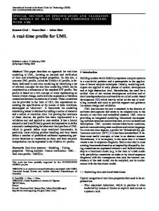
• XIS UML profile: a set of coherent UML extensions (which are presented in this paper) that allows a high-level, visual modeling way to design interactive systems; • ProjectIT Approach: a software development approach inspired on a set of best practices, namely: (1) based on high-level models or specifications; (2) supported by component-based software architecture; and (3) using generative programming techniques. Essentially, the ProjectIT Approach follows the MDA philosophy combined with the use of a domain-specific language oriented towards requirements specification. Figure 1 presents an overview of the ProjectIT Approach, in particular its main actors and corresponding tasks. • ProjectIT-Studio platform [10]: a CASE tool to support the ProjectIT approach. ProjectIT-Studio is currently in development on top of the Eclipse.NET platform [11]. This tool supports the definition of any UML profile (since the ProjectIT approach does not depend on the XIS profile) and the application of model-to-model transformations defined in the context of such profiles. Generically, the ProjectIT approach receives system requirements (e.g., functional, non-functional and
Figure 1 – Overview of the ProjectIT Approach.
development requirements) as its main input, and produces a set of artifacts (e.g., source code, configuration scripts or data scripts) as its main output. The tasks performed by the ProjectIT Architect are critical to the ProjectIT approach. The architect performs the following tasks: (1) define a suitable UML profile (in the case of interactive systems, it can be the XIS profile as proposed in this paper; however, the ProjectIT approach is profile-independent, which means other profiles can be used); (2) define “Model2Model Transformation Templates” to produce new models; and finally (3) define “Model2Code Transformation Templates” to produce software and documentation artifacts from models, using generative programming techniques. It is important to mention that all of these templates and profiles can typically be used in other systems, so there is no need for the ProjectIT Architect to develop them for each individual system. It is the Designer’s responsibility to produce an integrated set of models (the “Design System” task). The designer can also apply model-to-model transformations based on the templates provided by the ProjectIT Architect, allowing the acceleration of the design task. After the design of the model, Programmers apply model-to-code transformations (i.e., generative code techniques) based on the templates provided by the ProjectIT Architect. Afterward, Programmers produce specific components that are not yet addressed by the profile or the artifact generator (such as adapters or business logic), as represented in Figure 1 by the “Complete Software Code” task. Finally, Testers and Integrators prepare and perform different tests in order to guarantee system quality.
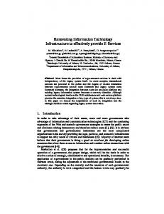
entities”, which are compositions of typical domain entities (please see “Entities View”, Section 4, for details). Separation of concerns: Software systems have to handle different concerns, such as data design issues, functional concerns, and non-functional concerns (e.g., security and performance). In order to face these concerns, abstraction and isolation are essential. XIS adopts these best practices by providing multiple views for interactive systems design, and by minimizing dependencies among those views. Use-case-driven approach: XIS addresses the identification of actors and use cases (which is typical in traditional model-driven development approaches), to manage the main functionality of the system and to obtain information about roles and related permissions. Model transformations: In order to provide flexibility and productivity at design time, XIS features two different design approaches (which are presented in Section 7) that are based on the extensive use of model transformations. Figure 2 shows the multi-view organization proposed by XIS. There are three main concerns that are captured through complementary views, namely the entities, use-cases, and user-interfaces views. Other concerns (and so other views) could be integrated in future work (e.g., views for specifying non-functional requirements such as security, reliability, performance, scalability or usability).
3 The XIS Overview
The second version of the XIS UML profile is a coherent group of UML extensions that allows us to model interactive systems according to the ProjectIT Approach (briefly presented in Section 2). In spite of XIS being a key element of ProjectIT and supported by the ProjectIT-Studio tool, it should be emphasized that XIS is just a UML profile [12, 13], and so it can be used and supported by different CASE tools. However, using the XIS profile in another CASE tool requires that developers implement model-to-model and modelto-code transformations in that tool. XIS design follows some principles that are fundamental to model-driven development, namely: (1) modularization; (2) separation of concerns; (3) usecase driven approach; and (4) model transformations. Modularization: Modularization is fundamental when modeling large systems, and XIS addresses it through the use of packages, and the concept of “business
Figure 2 – The multi-view organization of XIS.
In the following sections we describe and discuss the relevant aspects of XIS based on these views. For
better understanding and simplicity of the explanation we use a small case study, the “MyOrders System” (see table below). A Small Case Study – The MyOrders System MyOrders is a system that allows keeping relevant information for every organization. The MyOrders system manages business entities such as products, suppliers, customers and orders. There is information associated with each entity; for instance, a product has a name, a price and an indication of how many units are in stock. An order can cover multiple products (i.e., it is not necessary to create an order for each product to be acquired). However, the system keeps the information regarding an order and an acquired product as the “order details”. A supplier and a customer are third-party entities, usually companies, which can have multiple affiliates (i.e., multiple contacts). Additionally, each affiliate is of a certain type, which is identifiable by its name. There are some differences between a supplier and a customer: (1) a supplier cannot place orders, as it is only responsible for supplying products, not for consuming them; (2) a customer can only acquire products by placing an order; and (3) a customer is associated with one or more markets (identified by their name). […]
enumerations (if they exist) and their enumeration values. The reason for the existence of these stereotypes, instead of just using a typical UML class diagram, is that these stereotypes provide a range of tagged-values that are meant to be used for purposes such as the generation of documentation (by using a “description” tagged-value) or the generation of the source code that will be used by the various layers of the interactive system. Figure 3 illustrates the Domain View for the MyOrders case study, with the relevant stereotypes applied (the tagged values are not displayed, for diagram simplicity).
4 Entities View
After specifying the requirements for an interactive system, a fundamental stage in the creation of the system is the identification of the problem domain and, afterward, the modeling of its entities. The XIS profile addresses this stage by offering the Entities View, which in turn consists of the Domain View and the BusinessEntities View. In the Domain View, the Designer places the classes and relationships that correspond to the problem domain. In the BusinessEntities View, the Designer defines business entities (entities with a higher level of granularity), which aggregate entities from the Domain View or even other business entities.
4.1 Domain View The Domain View is used to model the entities that are relevant to the problem domain in a traditional way, by using classes. The relationships between entities are modeled using simple associations, aggregations and inheritance. In addition, the designer defines the state of each class by using attributes; to support the definition of these attributes, the designer can also define enumerations. The XIS profile provides stereotypes to be applied to elements in this view, namely: (1) XisEntity and (2) XisEntityAttribute are applied to classes and their attributes, respectively; and (3) XisEnumeration and (4) XisEnumerationValue are only applied to
Figure 3 – Domain View.
4.2 BusinessEntities View The purpose of the BusinessEntities View is to provide entities of a coarser granularity, known as business entities. These business entities are the highlevel entities that will be manipulated in the context of a certain use case (as explained in the next section, “Use-Cases View”). A business entity is specified by designating a domain entity (from the Domain View) as its master entity, and by possibly designating other domain entities as its detail entities. The “master entity” establishes a context to restrict the set of “detail entities” that will be manipulated in the context of that business entity. Of course, in the Domain View, these detail entities should be associated with the master entity, otherwise providing such a context would not make sense.
In this view the designer can also specify “detail” associations between domain entities (depending on whether the domain entities have associations between them in the Domain View). Of course, these “detail” associations only make sense in the context of the current business entity – just because a certain “detail” exists in the definition of a certain business entity, does not mean that there will be a “detail” in every business entity. To define such a “detail” association in the context of a business entity, the corresponding stereotype provides a tagged-value that indicates the name of the business entity to which it belongs. A business entity can also be an aggregation of other business entities. This allows the creation of business entities that are not directly related to a specific domain entity (by a “master” or “detail” relationship), but rather to concepts that have been defined as business entities. For example, in the context of MyOrders, suppose an Order would be an higher-level concept that would only involve a Customer and a Product (or a group of Products), and that an Order would have no OrderDetails and no attributes (i.e., an Order would not have an internal state, so it would not be necessary to represent it in the Domain View); if this was the case, then a way to model an Order would be to create a business entity, OrderBE, that would be composed of a business entity representing a customer, CustomerBE, and a business entity representing a Product, ProductBE, as Figure 4 illustrates. To keep the Designer from making mistakes while modeling the system, a business entity cannot be composed of other business entities and designate master/detail entities.
“Operations” tagged-value, typed as a list of strings, which allows the specification of which operations make sense in the context of the current business entity. These operations can be standard operations, such as “new”, “edit”, “select” or “delete” (which will be recognized by the ProjectIT-Studio code generator), or custom operations, which must be later specified by the Programmer. Note that these operations are not UML operations. The concept of business entity exists to provide a single entity (of a coarser granularity than domain entities) to be manipulated by one (or possibly multiple) use cases. It allows the definition of the set of domain entities that must be accessed and/or manipulated in the context of a certain use case. Figure 5 illustrates the definition of the business entity SupplierBE (tagged-values are not shown for diagram simplicity). This business entity specifies the domain element Supplier as its master entity, and specifies the domain entities Affiliate and Product as its directly accessible details.
Figure 4 – A business entity composed by other business entities.
This view defines the following stereotypes: (1) XisBusinessMaster is used to identify the “master” domain entity which the current business entity represents; (2) XisBusinessDetail is used to indicate a “detail” domain entity; (3) XisBusinessEntity is applied to the class that represents the business entity; and (4) XisBusinessComposition indicates that the business entity is a composition of other business entities. The XisBusinessMaster, XisBusinessDetail and XisBusinessComposition stereotypes define the
Figure 5 – Definition of the Supplier business entity.
Additionally, it is worth noting the “detail” association between Affiliate and AffiliateType. This association means that, in the generated application, when the user selects an Affiliate, the corresponding AffiliateType will also be accessible in any use case that manipulates the SupplierBE business entity.
5 Use-Cases View
The Use-Cases View is used to define the actors (or roles) of the specific system, as well as to define use cases, and establish the corresponding permissions. These aspects are modeled in the Actors View and the UseCases View.
5.1 Actors View The Actors View specifies the entities (i.e., actors) that can perform operations. They are related through inheritance relationships, so that the child-actor can perform all operations allowed by the parent-actor. This view uses a single stereotype: (1) XisActor, which represents any role that can perform operations. This stereotype exists because it provides a range of tagged-values (such as “description” and “isSuperActor”) that are meant to be used during the generation of artifacts. The MyOrders example, from Figure 6, shows that “UAdmin” and “UManager” can perform all operations allowed by “URegistered”, and that all actors can perform the operations of “User”.
Figure 6 – Actors View.
5.2 UseCases View The UseCases View describes the relationships between the actors defined in the Actors View and the operations they are allowed to perform over business entities. The Designer can specify use cases by performing the recommended following steps: (1) creating the use case; (2) creating the necessary actors and associating them to the use case; and (3) creating the business entity (or entities) that will be manipulated by the use case. Of course, this view uses the actors defined in the Actors View and the business entities defined in the BusinessEntities View. It also defines the following stereotypes: (1) XisUseCase, which represents a use case, as a set of operations that an actor can perform
over a business entity while interacting with the system; and (2) XisOperatesOnAssociation, which represents an association between a use case and a business entity, and defines the list of operations that the use case can perform over that business entity. The operations of a use case over a business entity must be a subset of those defined in the business entity itself (in the “Operations” tagged-value from the XisBusinessMaster association). This allows the Designer to reuse business entities between use cases (if those use cases are relatively similar), by simply specifying a subset of the operations that the business entity supports. An example of this is depicted in Figure 7, in which the “UManager” actor is allowed to perform the typical CRUD operations over the “Customer” business entity, while the “URegistered” actor is only allowed to create new customers; the range of allowed operations is restricted, but the business entity is the same, thus avoiding an explosion of business entities in the BusinessEntities View.
Figure 7 – UseCases View.
6 User-Interfaces View
The User-Interfaces View is used to define the interaction spaces (i.e., abstract “screens” that receive and present information to end-users during their interaction with the system) of a system, and the navigation flow between them. The User-Interfaces View consists of the NavigationSpace View and the InteractionSpace View. The NavigationSpace View defines the navigation flow that can occur between any of the interaction spaces. The InteractionSpace View defines the user-interface interaction elements that are contained in each interaction space; this view can also specify access control between actors and user-interface elements.
6.1 NavigationSpace View The main purpose of the NavigationSpace View is to describe the navigation flow between the identified interaction spaces. This view is useful to support the documentation of the system structure giving the chance to easily change and improve the navigability. This view defines a single stereotype: (1) XisNavigationAssociation, which represents a navigation flow between two interaction spaces showing the direction of the transition. Although this stereotype does not currently define any tagged-values, this situation will probably change in future evolutions of the XIS profile (e.g., with tagged-values to perform validation tasks), as we pursue additional avenues of research. Figure 8 presents a small example of a Navigation View representing part of the MyOrders case study (the XisNavigationAssociation stereotype is applied to all the associations represented in the figure; however, the stereotype labels have been removed for diagram simplicity). Using this model we can describe the navigation flow between different interaction spaces.
Figure 8 – NavigationSpace View.
This model is used only to define how the end-user will navigate through the various interaction screens. It differs from classical navigation models [14] because all screens must be specified explicitly, otherwise the artifact generation techniques may not be able to generate all the source-code to implement the system’s navigation flow. However, this does not invalidate the use of such classical navigation models if necessary, because model-to-model transformation templates could be defined in order to transform XIS-based navigation models to classical navigation models and vice-versa. The user-interface elements contained in each interaction space are not specified in this view, to keep navigation flow diagrams simple. Instead, the
specification of those elements is done in the InteractionSpace View.
6.2 InteractionSpace View The main purpose of the InteractionSpace View is to describe the contents and the overall organization of the different interaction spaces. This view uses some sketching techniques, based on the graphical layout of UML diagrams, to provide hints about the size and relative position of the elements that belong to each interaction space. Although an approach based on the graphical information of a diagram is usually not recommended (because traditionally each tool saves and displays diagrams in its own particular way), we believe that this is no longer an issue, because of the UML Diagram Interchange specification [15], which provides a standard way to store the graphical information of a UML diagram, in a manner that is independent of tools. This view defines the following stereotypes: (1) XisInteractionSpace, which is an interaction space; (2) XisInteractionCompositeElement, a composite interaction element which contains other interaction elements; (3) XisDomainElement, an interaction element that is associated with a XisEntityAttribute from the Domain View; (4) XisOtherElement, an interaction element which is not associated in any way with a XisEntity (e.g., a label or an image); (5) XisDataTable, an interaction element which displays a table with the result of a SQL query; (6) XisActionElement, an interaction element which is responsible for invoking an action or an operation (e.g., a button or a link); and (7) XisElementRight, which specifies access control between actors and interaction elements. An important aspect in this view is the XisInteractionCompositeElement. This element allows the grouping of other interaction elements (including other XisInteractionCompositeElements), following the Composite design pattern [16]. This composite grouping is relevant because it allows the Designer to specify a particular context for a XisInteractionCompositeElement, which is then accessible to the interaction elements contained within the composite element (e.g., if a XisInteractionCompositeElement is associated to a certain domain element, then all interaction elements contained within the composite element will have that domain element as context, and they can show information about that element, such as the value of a attribute). Figure 9 illustrates the Order_ISpace interaction space of our case study MyOrders. Figure 10 illustrates this same interaction space as a Windows Form,
obtained by using ProjectIT-Studio’s support for modeling and automatic artifact generation.
7 Design With XIS
After the introduction of the XIS profile’s main concepts, there are some additional aspects that must be considered by developers when using this profile: (1) the dependencies among its views; and (2) the design approaches that can be supported by XIS.
7.1 Dependencies Among Views Obviously, the multiple views proposed have dependencies among themselves, which can influence the design approaches that can be supported by XIS.
The Domain View, being the first and most important definition of the problem domain (aside from requirements, which are not yet regarded in XIS), does not depend on any other view. However, the BusinessEntities View depends on the Domain View to provide the domain entities that are used to create business entities. The Actors View is independent of all the other views. The UseCases View depends on the BusinessEntities View and the Actors View, as XIS’ use-cases are associated to actors and business entities. The NavigationSpace View and the InteractionSpace View depend on each other. The InteractionSpace View also depends on: (1) the Domain View, because some UI elements are associated with a domain entity; and (2) the Actors View, to establish access control between actors and the UI elements that each actor can access. Additionally, the NavigationSpace and the InteractionSpace views can be automatically generated, based on the other four views (Domain, BusinessEntities, Actors, and Use-Cases).
7.2 Supported Design Approaches Because of the optimal usage of model transformations, XIS proposes two different modeling approaches: the smart approach and the dummy approach, which are illustrated in Figure 11 and Figure 12, respectively.
Figure 9 – The Order_ISpace interaction space.
Figure 10 – The Windows Form corresponding to the Order_ISpace interaction space.
Figure 11 – XIS’ multi-view organization – the smart way.
According to the smart approach, the Designer only has to design the Domain, BusinessEntities, Actors, and UseCases views. Afterward, the time-consuming design of user-interface models can be avoided through automatic generation. After generating those models, the Designer can still customize them in order to support specific requirements, i.e., requirements not captured and supported by the involved model-tomodel transformation templates. On the other hand, according to the dummy approach, the Designer should produce the Domain, Actors, NavigationSpace and InteractionSpace views. The other views, i.e. the BusinessEntities and UseCases views, can also be produced, which could be useful from the documentation point of view; however, they would be useless from the model-to-code transformations perspective. The dummy approach is not recommended because it does not follow the general principles of model-driven development, but can be necessary if model-to-model transformation features are not available in the modeling tool.
the necessary business entities (using business entity compositions if it helps to re-use business entities between use cases), in the BusinessEntities View, associate them with use cases (specifying the operations that each use case must perform over the business entities), and also associate them with the relevant domain entities. Of course, the Designer is not forced to perform these steps in any particular order (e.g., the business entities could be created before the domain entities). When these four views have been defined, the modelto-model transformation can be applied to generate the User-Interfaces View. Afterward, the Designer can tailor these models, if the obtained results are not totally satisfactory. Note that this recommended approach is very similar to what is suggested by traditional model-driven development approaches, and so it is not a novelty introduced by XIS. However, unlike other approaches, XIS allows the developer to take advantage of these views to automatically generate (and possibly customize) the user-interfaces for the system, which can be a decisive factor for the acceptance of the system by its end-users.
8 Related Work
Figure 12 – XIS’ multi-view organization – the dummy way.
7.3 Recommended Design Approach The XIS smart approach is naturally recommended, as its model-to-model transformations considerably accelerate the modeling task. Nevertheless, we also recommend the following sequence of steps when designing the model: (1) create the necessary use cases, in the UseCases View; (2) create the necessary actors, in the Actors View, and associate them to the relevant use cases; (3) create the domain entities, in the Domain View; and (4) create
XIS is an UML profile for modeling interactive systems, based on the “separation of concerns” principle. In that spirit, XIS proposes a minimal set of views regarding the design of this kind of systems: Entities, Use-Cases and User-Interfaces views. In the context of interactive systems and userinterfaces modeling, based on UML extensions, there are other initiatives that should also be mentioned, in particular: User-Experience (UX) [17], Wisdom [18], UMLi [19], UWE [20], OVID [21], and CUP [22]. The UX approach defines modeling elements for the navigation design and discusses the transformations of UX UML models into code-level models for specifically the Java Struts framework. The Wisdom and the UX approaches represent quite well navigation aspects with some similarities with our NavigationSpace View, but don’t define any model to represent each node of the user interface in an abstract way as we propose in XIS. The Wisdom approach aims to maintain synchronization between Wisdom and Canonical Abstract Prototypes [23], which represent each node of the user interface in an abstract way. The UMLi approach proposes a profile to capture the conceptual, presentation and behavior aspects of systems. The UWE approach focuses particularly on modeling Web systems. The proposals in UMLi and UWE, for the presentation design have some similarities with our InteractionSpace View. The OVID
approach aims to link the OVID UML models to AUIML language. Few of these approaches are making real efforts to develop UML tools to support the design of models with generative techniques. Additionally, XIS differentiates itself from the proposals previously presented, because it considers the trade-off between simplicity (a driver that justifies keeping models at the PIM level) and productivity (a driver that justifies the adoption of models transformation techniques) a crucial issue, unlike any of those proposals.
9 Conclusions and Future Work The XIS profile is a key element of the ProjectIT research program and, in spite of it being theoretically independent of the CASE tool, it is better understood and applied in its context. Currently, we are taking advantage of the XIS profile, on top of the ProjectITStudio CASE tool, to research and develop productivity features such as model-to-model and model-to-code transformations, as referred above. In the near future we will concentrate in the development of these transformation templates, as well as tuning the XIS profile accordingly. Aspects concerning workflows and non-functional requirements specification would also be research challenges of great interest. We also need to provide a common metamodel definition for the two main components of ProjectITStudio: ProjectIT-MDD and ProjectIT-RSL [9, 24]. The idea is to allow different system specifications approaches, namely through XIS UML models or RSL (Requirements Specification Language) specifications, and to research ways to map XIS UML models into RSL specifications and vice-versa. Finally, when ProjectIT and its supporting tools reach a sufficient maturity level, it is our intention to use them in real projects, to better test and prove the ideas we are proposing.
[7] [8] [9] [10] [11] [12] [13] [14] [15]
[16] [17]
[18] [19] [20] [21]
References [1] Kotonya, G., Sommerville, I., Requirements Engineering Processes and Techniques, New York. Jonh Wiley & Sons, 1998. [2] Constantine, L., and Cockwood, L., Software for Use, Addison-Wesley Publishing, 1999. [3] Preece, J., et al., Interaction Design, Wiley, 2002. [4] Silva, A., O Programa de Investigação “ProjectIT”, Technical report, V 1.0, October 2004, INESC-ID, in http://berlin.inesc.pt/alb/uploads/1/193/pit-white-paperv1.0.pdf [5] Silva, A. The XIS Approach and Principles. Proceedings of the 29th Euromicro Conference, IEEE Computer Society, 2003. [6] Silva, A., Lemos, G., Matias, T., Costa, M., The XIS Generative Programming Techniques, Proceedings of
[22]
[23] [24]
the 27th Annual Int. Computer Software & Application Conference, IEEE Computer Society, 2003. OMG. Model Driven Architecture. http://www.omg.org/mda/ Fowler, M., Patterns of Enterprise Application Architecture, Addison-Wesley, 2003. Videira, C., Silva, A., The ProjectIT-RSL Language Overview, UML Modeling Languages and Applications: UML 2004 Satellite Activities, Springer LNCS, 2004. Saraiva, J., Relatório Final de Curso – Desenvolvimento Automático de Sistemas, IST, July 2005. SourceForge.net: Eclipse.NET. http://sourceforge.net/projects/eclipsedotnet OMG. “White Paper on the Profile mechanism”, Version 1.0, OMG Document ad/99-04-07. OMG UML Working Group. Rumbaugh, J., Jacobson, I., Booch, G., The Unified Modeling Language Reference Manual, Addison Wesley, August 2004. Koch, N. and Kraus, A., The Expressive Power of UML-based Web Engineering. In Proceedings of IWWOST02, 2002. OMG. Unified Modeling Language: Diagram Interchange – Specification Version 1.0, April 2006. http://www.omg.org/cgi-bin/apps/doc?formal/06-0404.pdf Gamma, E., et al., Design Patterns: Elements of Reusable Object-Oriented Software, Addison-Wesley, 1995. Kozaczynski, W. and Thario, J., Transforming User Experience Model To Presentation Layer Implementations, Proceedings of the Second Workshop on Domain-Specific Visual Languages, OOPSLA 2002. Nunes, N. J. and Cunha, J. F., Towards a UML profile for interaction design: the Wisdom approach, In UML 2000, Springer, 2000. Silva, P. P., and Paton, N., User interface modelling in UMLi. IEEE Software, 20(4), July–August 2003. Hennicker, R. and Koch, N., Modeling the User Interface of Web Applications with UML, Proceedings of the Workshop pUML-Group at UML 2001. Azevedo, P., Merrick, R., and Roberts, D., OVID to AUIML - User-Oriented Interface Modelling, Proceedings of the Workshop - Towards a UML Profile for Interactive Systems Development, Tupis, 2000. Bergh, J. and Coninx, K., Towards Modeling ContextSensitive Interactive Applications: the Context-Sensitive User Interface Profile (CUP). In Proceedings of the ACM Symposium on Software visualization, 2005. Constantine, L., Canonical abstract prototypes for abstract visual and interaction design. In Proceedings of DSV-IS 2003, Springer, LNCS 2844, 2003. Videira, C., Silva, A., Patterns and metamodel for a natural-language-based requirements specification language, in Proc. of the CaiSE’05 Forum, 2005.