Abstract. In the last years, the software development based on mobile agents has received ... design phases of mobile-agent applications development.
Modeling of Mobile-Agent Applications with UML Edgardo A. Belloni and Claudia A. Marcos ISISTAN Research Institute - Facultad de Ciencias Exactas - UNICEN Paraje Arroyo Seco - Tandil (B7001BBO) - Buenos Aires, Argentina. Tel/Fax: + 54–2293–440362/3 – URL: http://www.exa.unicen.edu.ar/~isistan/ E-mail: {ebelloni, cmarcos}@exa.unicen.edu.ar Abstract. In the last years, the software development based on mobile agents has received important attention because it introduces a new development paradigm for widely distributed and heterogeneous systems. Up to now, the usual approach for mobile-agent applications development has been focused on the implementation phase, mainly because of the vast lack of suitable modeling techniques or methodologies in the domain. In this sense, the development of powerful abstractions for the modeling of mobile agents becomes increasingly important. In this article, we present an approach to deal with the lack of appropriate concepts and notations in the standard Unified Modeling Language (UML) to capture relevant abstractions for the modeling of mobile-agent features. This approach is materialized by a coherent and comprehensive set of views and models, which extends UML contributing to the analysis and design phases of mobile-agent applications development. Keywords. Mobile Agents; UML Extensions; Agent Oriented Software Engineering (AOSE).
1
Introduction
Agent mobility [29][10][16] – i.e., the software agents’ capability of moving across the Internet while they are acting on behalf of a user – is being recognized as one of the most promising features for Internet applications development. The mobility of an agent involves the transfer of its code, data, and possibly its execution state, towards the environments or sites where the resources it needs to access, or where other agents it needs to meet, are allocated. Such capability is particularly interesting when an agent makes sporadic use of a valuable shared resource. Efficiency, for instance, can be improved by moving agents performing queries over a large database to the host of the database itself. Additionally, response time and availability would improve when performing interactions over network links subject to long delays or interruptions of service. In the last years, many agent-oriented modeling techniques and methodologies have been developed [13][30][31][12]. However, none of these techniques can yet be regarded as a comprehensive methodology for the analysis and design of multi-agent systems. Moreover, very little work has been made defining concepts and notations to model mobile agents restricting, as a result, the usefulness of the existing AOSE methodologies for Internet applications development. In fact, in the near past, works on the mobile agents area have mostly been technology-driven focusing in the development of many different frameworks or platforms to support agent mobility. A lot of effort has been invested developing these infrastructures both within the research community and within commercial projects (c.f., [25]). However, in spite of these efforts, there is yet little evidence of an engineering approach to the
development of mobile agent-based applications [13][17][12]. Up to now, the usual approach for this development has been focusing on the implementation phase; applications are directly implemented in an ad-hoc fashion by selecting and using a particular platform supporting agent mobility, following little or no rigorous modeling technique or methodology. This approach consequently produces insufficient specifications concerning relevant requirements, analysis or design aspects of mobile agents. At present, the Unified Modeling Language (UML) [26][24] is being recognized as a satisfactory medium to support agent-oriented modeling [12]. Although UML is the standard language for documenting systems in the object-oriented paradigm, there are considerable similarities between this paradigm and the agent-oriented one [30]. Additionally, UML is an extensible language since it provides built-in mechanisms to introduce new elements for specific domains such as agent-based modeling, the case in point. In this sense, to develop powerful abstractions by extending the UML for the modeling of agent-based systems becomes increasingly important. Only recently, in the last two years, a few works were initiated trying to deal with the lack of appropriate concepts and notations in the standard UML for the modeling of mobileagents applications (c.f., [17][21] and [20]). These works have essentially proposed extensions to some particular UML diagrams for representing basic features concerning agent mobility, in a high-level of abstraction. However, although these extensions are interesting contributions, they yet represent partial approaches for the modeling of mobile-agent features and applications. We argue that more work must take place in order to explore how UML can be used and extended to capture relevant abstractions in the mobile-agent paradigm. In this article, we present an approach in order to improve the standard UML concerning the specification of relevant analysis, design or implementation aspects of mobile agents, by defining a coherent and comprehensive set of views and models. This set unifies the line of the contributions in the area and it incorporates new abstractions and mechanisms identified as necessary to model mobile-agents applications, particularly during the analysis and design phases of their development. The article is structured as follows. Next section introduces the mobile-agent paradigm discussing its basic concepts, antecedents and benefits. Additionally, several functional and technical features of this kind of agents are described. Section 3 provides an overview on the UML and its extension mechanisms. Section 4 reviews previous approaches extending the standard UML to partially model mobile-agent features. Then, in section 5, the rationale and motivations for our approach are analyzed and, our proposal involving several views to model relevant abstractions in the mobile agent paradigm is presented. Section 6 provides a summary of ongoing experimental works in order to evaluate the effectiveness of the approach. Finally, some concluding remarks are delineated and options for future work are discussed.
2
The Mobile-Agent Paradigm
In the last years, the software development based on mobile agents has received important attention because it introduces a new development paradigm for widely distributed and heterogeneous systems. The most essential concepts of this paradigm are (mobile) agents and places [29]. In a broad sense, an agent is a software
component that executes specific tasks on behalf of someone (a person) or something (an organization or another agent) with some autonomy – i.e., its actions could be not only determined by external events or interactions, but also by its own motivation (or purpose). Agents can be classified along several primary attributes that agents could exhibit, such as reactivity, pro-activity, social ability and mobility [22]. With respect to mobility – i.e., the agent’s ability to move around some computer network, and a.k.a. migration or navigation – there are two kinds of agents: mobile and stationary (static or non-mobile) agents. Additionally, an agent can play several roles and conversely multiple agents can play the same role; a role describes external features of an agent in a particular context. Typically, an agent-based application involves several agents that interact and communicate between themselves, playing different roles. A mobile-agent application additionally involves a number of computational environments – a.k.a. mobile-agent systems or servers – where agent execution can take place and where different services and resources are provided. In this context, mobile agents are active entities that can move from a mobile-agent system to another one, in order to meet other agents or to access to services and resources provided there, while they are acting on behalf of someone or something. On the other hand, resources represent nonautonomous entities, such as files, objects, databases, programs or external applications, which can be used and shared by several mobile agents. A mobile-agent system is a software component, which acts as a dock station accepting agents and providing native resources for them. It is responsible for executing agent code through protected execution environments – a.k.a. execution places. A mobile-agent system is also responsible for providing other support features, such as agent persistence, security, and primitive operations to agent programmers, e.g., those that allow agents to migrate, communicate among them, access local resources, etc. Moreover, modern mobile-agent systems provide standard interfaces for interoperability with other mobile-agent systems, accepting agents implemented in different programming languages. In this context, execution places (or simply places) represent logical locations, provided by mobile-agent systems, where agents execute, meet and communicate with other agents, and manipulate some local resources. In general, agents, mobile-agent systems, places and resources are uniquely identified by a name or an electronic address. One o more mobile-agent systems can exist in a node. A node represents a hardware infrastructure on which both agents and mobile-agents are actually executed. Typically, a node is a computer, but in the near future, this term will probably include other computing devices, such as personal digital assistants or mobile phones. Finally, a logical network of places materializes a region. The places in the region are associated to the same authority, e.g., an organization or administrative domain. The region registers each agent that is currently hosted by a place provided by a mobile-agent system of the region. If an agent moves to another place, this information is updated. 2.1
Antecedents, Benefits and Applications
Essentially, the mobile-agent paradigm has evolved from two antecedents: clientserver and remote evaluation paradigms [16]. Traditionally, distributed applications have relied on the client-server paradigm in which client and server processes
communicate either through message-passing or remote procedure calls (RPC). This communication form is synchronous, i.e., the client suspends itself after sending a request to the server, waiting for the results of the call. In the early nineties, Remote evaluation (REV) was proposed as an alternative paradigm. In REV, the client rather than invoking a remote procedure sends its own procedure code to a server, and requests the server to execute it and return the results. In RPC, data is transmitted between the client and server in both directions. In REV, a code is sent from the client to the server, and data is returned. In contrast, a mobile agent is a program (encapsulating code, data and execution context) sent by a client to a server. Unlike a procedure call, it does not have to return its results to the client. It could migrate to other servers, transmit information back to its origin, or go back to the client if appropriate. Mobile agents can be also considered as the last point of the incremental evolution of mobile abstractions such as mobile code, objects, and process [29]. A transferred state of mobile code such as applets consists only of code. A mobile object state consists of code and data. A mobile process state, in addition, includes the thread state. The mobile agent state consists of code, data, thread and authority of its owner. According to the movement pattern, mobile agents differ from applets (downloaded from the server to the client) as well as from servlets (uploaded from the client to the server) in that mobile agents can have multiple hops, and that they can be detached from the client. A mobile agent autonomously visits places without interacting continuously with its originating place. This originating place gets involved only when the agent is sent to the first visiting place, and when the agent returns from the last visited place. Several advantages of the mobile-agent paradigm, in comparison with other approaches for distributed systems, have been identified. The most important ones are seen in the possibility of reducing expensive global communication costs by moving the computation to the data and in the possibility to distribute complex computations onto several, possibly heterogeneous hosts. Mobile agents can be useful for the development of different systems domains, such as electronic commerce, distributed information retrieval, workflow management and cooperation, personal assistance, remote device control and configuration, and advanced telecommunication services, among other ones. These kinds of applications clearly benefit from using mobile agents because they reduce the network load, overcome network latency, execute asynchronously and autonomously, are fault-tolerant, and also can sense their execution environment and react dynamically to changes [19]. 2.2
Functional and Technical Features
Mobile-agent systems have a significant set of architectural issues as well as technical and functional features to support the development of mobile-agent applications. Several authors – c.f., [16][10] and [25] – have analyzed similar sets of these issues and features, in addition to alternative mechanisms, required as necessary to design and implement mobile-agent systems. In this context, the most important topics include: execution, management of agent types (or classes) and identifiers, persistence, mobility – including, migration of the agent’s code and execution state, and management of the agent’s data space after migration –, communication, access to external resources, and security. A complete description of all these topics is
beyond the scope of this paper; we shall only focus on the most relevant ones for our purposes: mobility and communication. 2.2.1
Agent Mobility
The primary feature of mobile agents is their ability to migrate between an arbitrary set of execution places. In general, agent mobility is supported by two mechanisms: Migration and Remote Cloning. The migration mechanism suspends the execution of a mobile agent, transmits it to the destination place, and then resumes it. The remote cloning mechanisms creates a copy of a mobile agent at a remote place; cloning differs from migration because the original agent is not detached from its current location (place). Alternatively, agent mobility can be either Proactive or Reactive. In proactive mobility, the time and destination for migration are autonomously determined by the migrating agent. With reactive mobility, in contrast, the movement is triggered by a different entity that has some kind of relationship with the mobile agent to be migrated. As in migration, cloning can be either proactive or reactive. On the other hand, from the implementation point of view, a mobile agent represents an execution unit with an internal structure including: a code segment, which provides the static description for its behavior; and a state composed of a data space and an execution state. The data space is the set of references to resources that can be accessed by the agent. The execution state includes private data that cannot be shared, as well as control information, such as the call stack and the instruction pointer. In principle, each of these elements might move independently. The portion of a mobile agent that needs to be moved – i.e., its code, data, or execution state – is determined by composing orthogonal mechanisms supporting mobility of code and execution state with mechanisms for data space management. For this reason, we shall describe these kinds of mechanisms separately. Mobility of Code and Execution State The mobility of an agent involves the transfer of its code, data, and possibly its execution state, towards the places where the resources it needs to access, or where other agents it needs to meet, are allocated. From the point of view of the execution state, there are two approaches for its mobility: Strong mobility (or Statefull). In this case, a mobile-agent system has the ability to allow migration of both the code and the execution state of an agent to a different execution place. Agents can contain migration primitives at any point in the code, without requiring explicit state retrieval. When a migration primitive is executed, the agent’s current state (data and execution stack) and code are transferred to the destination place. On arrival, the agent resumes its execution at the instruction following the migration primitive. Weak mobility (or Stateless). In this case, a mobile-agent system only has the ability to allow code transfer across different places; code may be accompanied by some initialization data, but no migration of execution state is involved and the agent’s code execution is re-initialized after migration.
On the other hand, mechanisms supporting code mobility provide the capability to transfer code across mobile-agent systems and either link it dynamically to a running agent or use it as the code segment for a new agent. Such mechanisms can be classified according to: The direction of code transfer. A mobile agent can either fetch the code (code fetching) to be dynamically linked and/or executed, or ship (code shipping) such code to another mobile-agent system. The nature of the code being moved. An agent’s code involves not only the code of its specific type, but also the code closure – i.e., the code from all its inherited and/or referenced types. From the code closure point of view, there are three approaches for its mobility:
Code does not migrate. In this case, the agent’s code has to be preloaded by the nodes the agent might visit. Code closure migrates at once. The agent’s code is self-contained and self-sufficient (stand-alone code) and will be used to instantiate a new agent on the destination place. Code migrates incrementally. Only the basic, specific agent code migrates (code fragment). The remaining code – i.e., types inherited or referenced – migrates and is loaded dynamically (on-demand) at runtime. The synchronization involved. These mechanisms can be either synchronous or asynchronous, depending on whether the agent requesting the transfer suspends or not until the code is executed. The time when code is actually executed at the destination place. In asynchronous mechanisms, the actual execution of the code transferred may take place in either an immediate or deferred fashion. In the first case, the code is executed as soon as it is received, while in the deferred model execution is performed only when a given condition is satisfied.
Management of the Data Space Upon migration of an agent to a different location, its data space – i.e., the set of bindings to resources accessible by the mobile agent – must be reorganized. This situation may involves removing some bindings, re-establishing new bindings, or even migrating some resources to the destination along with the agent. The choice of a suitable strategy depends on: The type of the resources involved. The type of a resource determines whether a resource can be migrated over the network or not. In this context, resources can be either transferable or not transferable. For instance, a printer represents a not transferable resource. The requirements of the application. It might be undesirable to transfer resources for performance or security reasons. In this sense, according to applications requirements, transferable resource instances can be classified as free or fixed. The former can be migrated, while the latter are permanently associated with a particular location. The type of binding to such resources. Resources can be bound to an agent through three forms of binding, which constraint the mechanisms for data space management that can be used upon migration. These forms of binding are: By identifier. In this case, the agent requires that, at any moment, it must be bound to a given uniquely identified resource. By value. This kind of binding declares that, at any moment, the resource must be complaint with a given type and its value cannot change because of migration. By type. In this case, the agent requires that, at any moment, the bound resource is complaint with a given type, no matter what its actual value or identity are.
In this context, two kinds of problems must be addressed by the mechanisms supporting data space management upon migration of a mobile agent: resource relocation and binding reconfiguration. The existing mechanisms deal with these problems constrained both by the nature of resources and by the forms of binding to such resources. These mechanisms are: Binding Removal. In this case, when an agent migrates, its bindings to resources are removed. Subsequent attempts to access a resource through such bindings will arise an exception. This strategy is independent of the type of binding or resource; however, if access to resources must be preserved different mechanisms must be exploited. By Move. If an agent is bound to a resource by identifier, it is suitable to apply relocation by move in order to preserve resource identity. In this case, the resource is transferred along with the agent to the destination and the binding is not modified. This mechanism can be exploited only if the resource is a free transferable resource. Nevertheless, moving away a shared resource may cause problems to other agents that own bindings to the resource. This situation may be managed applying binding removal, i.e., to void bindings to the moved resource. A second approach is to retain the bindings to the resource at its new location by means of network references. Network Reference. This mechanism can be applied to free transferable resources, when it is necessary to preserve bindings in a source location because a resource is shared. In this case, the resource is transferred along with the agent, and the bindings that maintain other agents are modified to reference to the resource in the remote location. Alternatively, this mechanism can be applied to fixed or nontransferable resources. In this case, the resource is not transferred and once the agent has reached its
target location, the binding is modified to reference the resource in the original location. Every subsequent attempt of the agent to access the resource through such binding will involve some communication with the original location. By Copy. If an agent is bound to a transferable resource by value, the most convenient mechanism is management by copy because the resource identity is not relevant. A copy of the resource is created, the binding to the original resource is modified to refer to the copy, and then this copy is transferred to the destination along with the agent. Re-binding. If an agent is bound to a resource by type, the most convenient mechanism is re-binding. The binding is voided and reestablished, after the agent migration, to another resource on the target location having the same type of the original resource.
2.2.2
Communication between Agents
Agents can cooperate to solve complex situations from their individual capabilities, by interacting among them in order to communicate messages, knowledge, goals, plans, etc. With respect to communication and interaction between agents, it is important to discuss different aspects concerning their semantics, such as: Synchronicity. According to a temporal analysis, communication between agents may be synchronous or asynchronous. Communication is synchronous (blocking) when the agents involved synchronize themselves before transferring any data; it is suitable in scenarios where data transfers requires urgent confirmations, or in interactive dialogs. Alternatively, communication is asynchronous (non-blocking) when the agents do not need to meet. Locality. According to a spatial analysis, interaction between agents may be local or remote. When interaction is local, agents meet at a common place and may use any known inter-process communication mechanism – e.g., shared memory, files, environment variables or pipes. When interaction is remote, agents communicate from different nodes through message passing, RPC or any other remote communication mechanism. Destination. Usually, when an agent interacts with other agents, it follows a point-to-point communication pattern. However, there are situations in which an agent interacts with a dynamic set of agents using group communication, following a broadcast or multicast communication pattern. Intermediation. Finally, interaction between agents may be also direct or indirect. When interaction is direct, agents invoke each other’s methods explicitly. When interaction is indirect, agents do not communicate directly; they use an intermediation service, such as Object Request Brokers (ORB) or Servers of shared information spaces.
3
The Unified Modeling Language
The Unified Language Modeling (UML) [26][24] is a standard modeling language for visualizing, specifying, constructing, and documenting the artifacts of softwareintensive systems. UML is not a software development methodology; it is a graphical language to model the different (static, dynamic, implementation or external behavior) aspects of a software system. UML proposes to capture these different aspects in views or models; each of them using a set of diagrams – e.g., class or sequence diagrams. A diagram is a graphical representation of a set of abstractions, rendered as a connected graph of vertices (elements) and arcs (relationships) – e.g., classes, objects, structural relationships, or messages. The models supported by UML are the following: Static models. This group includes class and object diagrams. A class diagram shows a set of classes, (operation) interfaces, collaborations, packages (conceptual aggregations of UML elements), and their (association, generalization, realization or dependency) relationships. Class diagrams address, in general, the static design view of a system; while class diagrams including active classes (process or threads) address the static process view of a system. Alternatively, object diagrams represent static snapshots of instances of the elements found in class diagrams. Object diagrams address the same static views of a system as do class diagrams, but from the perspective of real or prototypical scenarios. Dynamic models. This group includes interaction, statecharts, and activity diagrams. An interaction
diagram shows a set of objects and their relationships, including the messages that may be dispatched among them. Both sequence diagrams and collaboration diagrams are kinds of UML interaction diagrams. On the other hand, statechart diagrams represent state machines, consisting of states, transitions, events, actions and activities. Statecharts are especially important in modeling the behavior of an interface, class, or collaboration and emphasize the event-ordered behavior of an object, which is especially useful in modeling reactive systems. Alternatively, an activity diagram – a special kind of a statechart diagram – shows the flow from activity to activity within a system. Activity diagrams are especially important in modeling the function of a system and emphasize the flow of control among objects. Interaction, statecharts and activity diagrams address the dynamic view of a system. External behavior model. This model includes use case diagrams. A use case diagram shows a set of use cases and actors and their relationships. Use case diagrams address the external behavioral view of a system; these diagrams are especially important in the specification of actions that a system can perform by interacting with outside actors. Implementation models. This group includes component and deployment diagrams. A component diagram shows the organizations and dependencies among a set of components. Physical aggregations of classes, interfaces, or collaborations are called components. In this sense, component diagrams address the static implementation view of a system. A deployment diagram shows the configuration of run-time processing nodes and the components that execute on them. Deployment diagrams address the static deployment view of system architecture; they are related to component diagrams in that a node typically encloses one or more components. Constraints model. UML is complemented with a simple formal language, the Object Constraint Language (OCL) [28], in order to express more semantics within a UML specification. OCL can be used to define constraints on a model, such as invariants, pre- and post-conditions of operations, and navigation paths within an object net.
3.1
UML Meta-model
Everything – i.e., each element or relationship – used in the UML diagrams has its own syntax and semantics, defined by the language with a meta-model. The UML meta-model defines the available concepts for the modeling of applications – i.e., it defines the language for specifying a model, while a model defines the language to describe an information domain. Each concept defined in an application is an instance of another concept defined in the meta-model. The UML meta-model is described in a combination of graphic notation, natural language, and formal language. Specifically, it is described by a semi-formal specification technique using the following complementary views [24]: Abstract syntax (UML + natural language). The abstract syntax defines what constructs exist in the language and how these constructs are built up in terms of other constructs, in a notation independent way. The concrete syntax is then defined by mapping the (graphical) notation onto the abstract syntax. This abstract syntax is presented in a UML class diagram showing the meta-classes defining the constructs and their relationships. Additionally, a short informal description in natural language describing each construct is supplied. For each meta-class, its attributes are enumerated together with a short explanation. Furthermore, the opposite role names of associations connected to the meta-class are also listed in the same way. Well-formedness rules (OCL). These rules describe the static semantics of UML, defining how an instance of a construct should be connected to other instances to be meaningful. The static semantics of UML meta-classes, except for multiplicity and ordering constraints, are defined as a set of invariant of an instance of the meta-class. These invariants have to be satisfied for the construct to be meaningful. The rules thus specify constraints over attributes and associations defined in the meta-model. Each invariant is defined by an OCL expression together with an informal explanation of the expression. Semantics (natural language). Finally, the dynamic semantics of UML is described by defining the meaning of each well-formed construct using natural language. The constructs are grouped into logical chunks that are defined together.
3.2
UML Extensibility Mechanisms
The standard UML provides concepts and notations, which have been carefully designed to cope with the modeling needs of typical software development projects. However, because of the diversity of application domains, developers may require additional notations or features beyond those defined in the standard UML. For this reason, UML provides built-in mechanisms to extend the language in controlled ways. These extensibility mechanisms include: Stereotypes. With a stereotype, we can create a new UML element from an existing one by defining its own special properties (providing its own set of tagged values), semantics (providing its own constraints), or notation (providing its own graphical representation or icon). We can think of a stereotype as a meta-type, because each one creates the equivalent of a new class in the UML metamodel. Tagged Values. Every element in the UML has its own set of properties; for instance, classes have names, attributes and operations. With stereotypes, we can add new elements to the UML; with a tagged value, we can specify a new kind of property that may be attached to an element. We can think of a tagged value as a meta-data because its value applies to the element itself, not its instances. Constraints. Everything in the UML has its own semantics. With constraints, we can add new semantics to any element. Essentially, a constraint specifies a condition that must be held true for one or more values of (part of) a model. Constraints may be written by informal explanations (as free-form text) or by OCL expressions.
A coherent set of extensions, defined for specific purposes using these extensibility mechanisms, constitutes a UML profile. For example, version 1.4 of the UML specification [24] includes a standard profile for modeling software development processes and another one for business modeling. In addition, it is worth mentioning that it is possible to extend the UML meta-model by defining new constructs following the specification technique previously described.
4
Mobile-Agent Modeling with UML: Related Works
In the near past, international organizations for the standardization of new technologies – e.g., the Object Management Group (OMG) [23] and the Foundation of Intelligent Physical Agents (FIPA) [9] – have been promoting the development of extensions to the UML for the modeling of agent systems. In the last years, many agent-oriented modeling techniques and methodologies have been developed – c.f., [13][30][12][8][1]. At present, the most complete agent-based extension for the UML is Agent UML [1]. Essentially, this formalism includes: sequence diagrams extensions supporting concurrent threads of interaction; a layered approach to agent interaction protocols; and a richer role specification enabling role modeling in several UML diagrams, among other useful agent-based concepts. However, research on providing suitable abstractions to model mobile-agents applications is very limited. In this context, there exist some preliminary proposals dealing with the lack of appropriate concepts and notations in the standard UML to model agent mobility – c.f., [17][21][20]. Klein et al. [17] have proposed some extensions to UML providing concepts for the modeling of (strong) mobility, remote execution (weak mobility) and cloning. Stereotyped classes are used to model mobile agents, while stereotyped components are used to model mobile-agent systems. Additionally, stereotyped packages are used to model both agencies (places) and regions. Structural relationships among these abstractions are represented in class diagrams. Agents moving from one location to
another are modeled, in sequence diagrams, by stereotyped messages (move, remote execution and clone) using the dependency relationship. Finally, stereotyped actions (move, remote execution and clone) are used to express, in statecharts, whether an agent will also change its location when its state is changed. Muscutariu et al. [21] have proposed an architectural description language (ADL) for the design of mobile-agent systems. This ADL is defined as a simple UML profile, presenting a minimum set of concepts and operation interfaces necessary for interoperability among heterogeneous mobile-agent systems. It proposes a graphical representation using deployment and component diagrams. Stereotyped components are used to model (mobile) agents, while stereotyped nodes are used to model (mobile) agent systems. In addition, packages are used to model both places and regions. Modeling of agent mobility is supported by the stereotyped flow relationship becomes, an operation move, and operations beforeMove and afterMove that prepare the agent for the migration. Mouratidis et al. [20] have introduced extensions at the UML deployment and activity diagrams to give answers to some questions that arise from the use of mobile agents. Their extended version of the deployment diagram allows developers to capture mobile agents (components), along with the platforms (nodes) they might visit – i.e., where the agents move. A stereotyped link (moves) specifies the movement of a mobile agent from one platform to another, accepting a parameter that specifies the reason – i.e., why the agent moves. Furthermore, different stereotypes (home, visitor and destination) can be applied to the agents to indicate the status of a mobile agent into a particular platform. On the other hand, these authors have proposed a particular interpretation of UML activity diagrams. In their approach, activity states model agent plans, transitions model events, the initial state represents the moment an agent migrates to a platform, while the final state represents the moment an agent leaves that platform. In this context, a parameter on the transition that leads to the final state indicates when an agent moves, by specifying the circumstances. Alternatively, an extended version of the activity diagram allows developers to capture how an agent reaches a targeted platform. In this case, deployment nodes are used instead of activity states, the initial state characterizes the dispatch of the agent from its home platform, and the final state characterizes either the return to its home platform or a platform in which the agent finishes a particular task. Flow from node to node describes the sequence of the agent movement (including the intermediate nodes between the home and the destination), while branches specify the decisions that drive the choice of particular intermediate nodes. Mobility is not only important as a programming concept, but that it is inherently introduced by the advent of mobile devices such as laptops, mobile phones, PDAs, etc. and hence has to be appropriately represented in corresponding models. In this context, it is worth mentioning that the approaches previously described can be used when there are only two kinds of entities: mobile agents and static locations; they are not well suited for mobile computing modeling. In order to deal with it, a few UML extensions have been proposed. Kosiuczenko et al. [18], have extended UML sequence diagrams to model objects that are mobile and can play the role of locations too. These diagrams generalize the concept of object lifeline of Use Case Maps [7] to model complex mobility patterns, providing also the possibility to abstract away from irrelevant details. Alternatively, Baumeister et al. [2] have proposed to extend UML
class and activity diagrams to model mobile systems, assuming that mobile objects can migrate from one location to another, while these locations can be nested and mobile too.
5 Towards Modeling
a
Comprehensive
Proposal
for
Mobile-Agent
Although the UML extensions described above are useful and practical contributions, they yet represent incomplete approaches for the modeling of mobile-agent features and applications. In this sense, an attractive trend seems to be the definition of a unique UML extension integrating the features of these different approaches. Nevertheless, more work must take place in order to explore how UML can be used and extended to model other relevant abstractions in the mobile-agent paradigm, which are not captured with such approaches. Particularly, we argue that it is yet necessary to give answers through modeling to some questions that also arise during analysis and design phases of mobile-agent applications development, such as: Which are the entities involved in the application and which are the structural relationships among these entities? Essentially: Which are the types of agents involved?; Which are the types of resources manipulated and shared by these agents?; Whom an agent represents?; Which are the roles that an agent could play?; Which are the platforms or mobile-agent systems involved?; Which are the services and execution places provided by these mobile-agent systems?; How these mobile-agent systems are organized in regions in the context of the application?; Which are the types of bindings that an agent maintains to resources? What does an agent do during its life cycle? Fundamentally: Which are the places that a mobile agent visits?; Which are the activities performed by an agent? Which are the locations where these activities are performed? Which is the execution states pattern of an agent? Which is the type of mobility prescribed for an agent? Particularly: Is it proactive or reactive?; What portion of a mobile agent, i.e., its code, data or execution state, needs to be moved?; How the set of bindings to resources accessible by an agent, must be reorganized upon migration of the agent to a different location? Which entities (agents, roles or systems) need to communicate between them? Why these entities need to communicate? When these entities need to communicate? Is such communication synchronous or asynchronous? Is it local or remote? Is it point-to-point, broadcast or multicast? Is it direct? Do the entities use of an intermediation mechanism?
These issues have been identified from a bibliographical review of relevant analysis, design and implementation aspects of mobile agents [10][16][25][6], as well as, from own development experiences in the domain [3][4][5]. In this context, we have defined a coherent set of views and models that organize and integrate the line of the contributions in the area, also incorporating new abstractions and mechanisms in order to develop a more comprehensive approach dealing with the issues formulated. This set represents a preliminary UML profile, named MAM-UML – it stands for Mobile-Agent Modeling with UML. The MAM-UML profile currently includes views to model organizational, life cycle, interaction and mobility aspects of mobileagents applications. These views are described in the next sub-sections. 5.1
Organizational View
The organizational view describes the entities, and their structural relationships, involved in a mobile-agent application. This view addresses the static logical view of an application in the mobile agent paradigm. Stereotyped classes and packages are used to model the entities. Stereotyped active
classes allow developers to specify two types of agents: stationary and mobile agents. Stereotyped classes are used to specify both the roles, which can be played by agents in the application, and the resources, which can be manipulated and shared by several agents. Stereotyped packages allow developers to specify mobile-agent systems, execution places and regions. On the other hand, structural relationships among these abstractions are represented in a UML class diagram. It represents an analysis class model in the application domain. A stereotyped dependency relationship, named home, enables to specify the origin place of a mobile agent. In addition, a stereotyped association relationship (named acquaintance) enables to specify the existence of at least one interaction involving the entities concerned. In order to describe properties of the new stereotypes, different tagged values are also defined, such as: Identifier. It specifies the identifier of an entity in order to be uniquely recognized. It can be applied to regions, mobile-agent systems, execution places, agents and resources. Location. This tagged value specifies the current location place of a mobile agent or resource. Authority. It specifies persons or organizations. This tagged value can be associated to agents in order to specify whom they represent. It can be also associated to places, mobile-agent systems, and regions, in order to specify whom they accept as an officially legal authority, in the context of a particular application. State. This tagged value specifies the current execution state of a mobile agent, e.g., it can be active, suspended, etc. Clone. This tagged value specifies whether an entity is a clone. It can be applied to mobile-agents and resources. System Type. It specifies the type of a mobile-agent system. This value indicates whether the system is complaint to a standard interoperability interface, such as those defined by OMG or FIPA. Language. This tagged value specifies the programming language (or languages) that is used by a mobile-agent system for the coding of mobile agents. I can be also associated to places, which provides an execution environment for agents.
User_Server
United_Server
{language = Java}
{language = Java}
omg-masif
{system type = OMG-MASIF complaint}
{system type = OMG-MASIF complaint} omg-mafinder
provides
Airlines_Service_Provider
1 ..* 1 ..*
includes
includes
provides
1 ..*
1 ..*
Common_Place {language = Java}
registers
run on
1 ..*
Auctioning_Place
run on
{language = Java}
Personal_Assistant {authority }
run on
Travel_User_Preference {type = transferable}
manipulates
Employee_Agent
plays
offers
Ticket
0 ..*
{type = transferable}
{app requirement = free}
Meeting_Agent plays
plays
plays
Travel_Agent
Auctioneer
Administrative
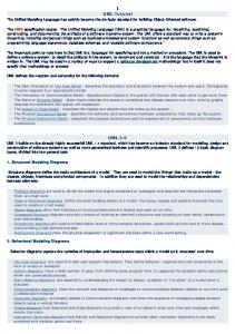
Figure 1. Organizational view of a mobile-agent application
Figure 1 provides a class diagram, which models the organizational view of a simple mobile-agent application. In such application, personal assistants move
between different places provided by two different mobile-agent systems, in the context of a region. These mobile agents act on behalf of some user and can play two different roles. Moreover, the diagram prescribes that these mobile agents at least interact, at auctioning places, with stationary employee agents. 5.2
Life-cycle View
The life-cycle view describes the itineraries, states and activities of each kind of mobile agent, during its life cycle. This view includes three models in order to specify that: a model of itinerary, a model of execution states, and a model of activities. Model of Itinerary Mobile agents move from a location (place) to another one, in order to meet other agents or to access to services and resources provided there, while they are acting on behalf of someone or something. Interaction diagrams, both sequence and collaboration ones can be used to specify the itinerary followed by an agent, during its life cycle. The standard UML provides two stereotyped messages, become and copy, which can be used to model correspondingly, agent migration and cloning. Although these stereotypes are useful in early phases of development, when it is necessary to model precisely the type of mobility that an agent uses other concepts need to be defined. For this reason, we define new stereotyped messages using the dependency relationship: strong move, weak move, and remote cloning. On the other hand, pro-active or reactive mobility can be explicitly recognized, in interaction diagrams, depending on who send such messages to the agent; the agent it-self, in the case of pro-active mobility, or a different entity in reactive mobility. Additionally, constraints associated to the mobility messages enable to specify why and when an agent moves.
2: bid( )
ta / Travel_Agent :
/ Auctioneer :
Personal_Assistant
Employee_Agent
{location = auctioning
{location = auctioning
place in United Server} place in United Server} 1.1: dispatch( ) {Why: to collect information and bidding on resources} 2.1: dispatch( ) {When: the user indicates to do it} {When: current price exceeds user’s preferences or auction ends} {Why: to collect information and bidding on resources} 1: dispatch( )
ta / Travel_Agent :
ta / Travel_Agent :
/ Auctioneer :
Personal_Assistant
Personal_Assistant
Employee_Agent
{location = auctioning
{location = auctioning
place in TWA Server}
place in TWA Server}
{location = common 4: tenderBid( )
place in User Server}
3.1: dispatch( ) {Why: to deliver a lowest-cost travel ticket}
3: bid( )
i : Itinerary
tup :
{location = common
Travel_User_Preferences
place in User Server}
{location = common place in User Server}
Figure 2. Modeling of an agent itinerary
Figure 2 provides an interaction diagram that models an agent that moves between
different places, collecting information and bidding on resources to automatically deliver a lowest-cost travel ticket to the user that it represents. Specifically, the diagram models an instance (named ta) of the class Personal_Assistant, playing the Travel_Agent role, migrating between auctioning places provided by different servers (mobile-agent systems). The mobile agent begins its itinerary reacting to a message of the user. Along this itinerary, the agent interacts at each auctioning place with anonymous Employee_Agent instances playing the Auctioneer role. Model of Execution States This model specifies each kind of agent as a state machine, emphasizing its execution states as well as the events and actions that cause the transitions from one state to another. Typically, during its lifetime, agents can be in one of the following states: Start – i.e., the mobile agent was created and initialized, it is about to run; Active – i.e., the agent is running; Suspended – i.e., the agent execution is temporarily interrupted; Deactivated – i.e., its code and state are permanently stored, e.g., on a hard disk; or Terminated. At present, the most prominent patterns of execution states are: the persistent process model and the task-based model. The first one is adopted by mobile-agent systems supporting strong mobility, e.g., Telescript [29]. The second model is adopted by mobile-agent systems supporting weak mobility, e.g., Aglets [19]. An agent adopting a persistent process model begins in a start state, the agent progress to an active state (a composite state) where its persistent process is executed, and eventually it enters a state where the process is terminated. When a mobile agent is transported from one place to another, the process in the active state is temporarily interrupted; it enters in a suspended state. Next, its context is delivered to the destination place where the process is resumed, and it re-enters to the active state at the instruction it left off. On the other hand, an agent adopting a task-based model also begins in a start state. Then depending on a set of conditions, or events it receives, the agent progress through a network of tasks. Each task has its own state. However, when the agent moves to a new location the context of the currently executing task is lost. Before moving, the agent must indicate the first task to be started when it re-materializes on the destination place. A statechart diagram specifies the corresponding pattern of execution states for each mobile-agent class defined in the organizational view. Stereotyped actions allow developers to specify, whether the agent will also change its location when its state is changed, according the type of mobility that it uses: strong move, weak move or remote cloning. Pro-active mobility can be explicitly recognized, in the statechart modeling the behavior of a mobile-agent class, with such stereotyped actions associated to the corresponding transitions. In the case of reactive mobility, several statecharts can be used in order to show the synchronization between the entities that produce events triggering the migration and the agent to be migrated. Model of Activities This model describes the activities performed by a mobile agent when it is running – i.e., when it is active, a state in the previous model. A variant of an UML activity diagram is used to specify this model. Different
swimlanes break the diagram into the different types of places where an agent executes. Additionally, constraints associated to a transition between activities performed in different places, enable to specify why and when an agent moves. 5.3
Interaction View
This view describes which, why, when and how agents, roles, and mobile-agents systems need to communicate, by specifying interactions among these entities, their protocols and coordination mechanisms, from temporal and spatial perspectives. This view complements the life-cycle view in order to address the dynamic view of a mobile-agent application. Typically, the interaction view is refined through several iterations as long as new interactions are identified. It can be conveniently modeled by means of a number of interaction diagrams, i.e., there will be at least one of such diagrams for each interaction. As a first approach, in order to model an interaction in a high level of abstraction, we propose to use a UML collaboration diagram specifying the entities involved using the defined stereotypes in the organizational view. Plain and template collaborations allow developers to show the entities involved in the interaction without describe the details of the interaction protocol and the specific messages that are exchanged between the entities. Plain collaborations are used when we are modeling a specific society of entities that work together, while template collaborations are used to abstract the essential structural and behavioral aspects of a reusable interaction pattern. Additionally, different constraints associated to the collaboration enable the specification of other important aspects of an interaction, such as: the interaction motivator – e.g., a goal, state or situation of the initiator entity; the information achieved and supplied by each participant in the interaction; synchronicity; locality; destination; and intermediation. FIPA -English Auctioning -Protocol Auctioneer Participant ta / Travel_Agent : / Auction_Participant Personal_Assistant
{Motivator: auctioneer has a surplus set of tickets for flights and participants need tickets} { Synchronicity: asynchronous } {Lo cality: local}
participant
participant
auctioneer
ta / Travel_Agent :
ea / Auctioneer :
Personal_Assistant
Employee_Agent
provides
: Ticket
gets 0..1
0..1
Figure 3. Modeling a reusable interaction pattern using a template collaboration
In Figure 3, a reusable agent-interaction protocol is modeled by using a template collaboration. This collaboration specifies an Employee_Agent instance playing the auctioneer role, while an instance of the class Personal_Assistant plays a participant
role, in such protocol. Several other anonymous mobile agents also are participant in the interaction pattern. The communication between these entities is asynchronous and local. Furthermore, the personal assistant could get a ticket provided by the auctioneer. On the other hand, the details of the interaction protocol and the specific messages that are exchanged between the entities involved can be modeled using UML interaction diagrams. Alternatively, at this point, we propose to apply the Agent UML formalism [1] by using its layered approach to model agent-interaction protocols, as well as, its extensions to UML sequence diagrams supporting concurrent threads of interaction. 5.4
Mobility View
This view includes models for the specification of code and execution state mobility, as well as, the mechanisms used for data space management. In general, this view addresses the static physical view of a mobile-agent application. Model of Data Space Management Upon migration of an agent to a different place, its data space – i.e., the set of bindings to resources accessible by the mobile agent – must be reorganized. This model specifies both the types of resources manipulated by agents and the types of bindings to such resources maintained by these agents. Furthermore, this model specifies the mechanisms supporting data space management upon migration of a mobile agent. A UML collaboration diagram is used to model each agent’s migration. In order to describe relevant properties of the resource stereotype, two tagged values are defined: Type – i.e., the resource is transferable or not transferable; Application requirement – i.e., the resource is free or fixed. On the other hand, resources can be bound to an agent through three types of binding. In order to specify these types of binding, stereotyped association relationships are defined: by identifier, by value, and by type. The different mechanisms of data space management that can be used upon migration of a mobile agent – i.e., Binding removal, By move, Network reference, By copy or Re-binding, are modeled in the collaboration diagram with template collaborations among the entities involved – i.e., the agent, the resource, the mobileagent systems and places of origin and destination. Figure 4 summarizes these concepts. It describes that a mobile agent, specifically an instance of the class Personal_Assistant, is bound to a resource by value. The model prescribes that upon migration of this agent from a common place to an auctioning place, the by copy management mechanism is applied. Therefore, a copy of the particular Itinerary resource is created, the binding to the original resource is modified to refer to the copy, and then this copy is transferred to the destination along with the agent. On the other hand, specific structural and behavioral aspects of the management mechanisms are modeled in separated UML packages, using class and interaction diagrams or alternatively Agent UML notation, because they represent patterns that can be reused in the same application or other ones.
By - Copy - Data - Space Mngmt -Mechanisms User_Server origin MA -System
{language = Java} {system type = OMG - MASIF complaint}
destination MA System
Mobile Agent Resource Origin Place Destination Place Origin MA - System Destination MA -System
United_Server {language = Java} {system type = OMG - MASIF complaint}
cp: Common_Place
ap: Auctioning_Place
origin place
{language = Java}
destination place
resource
mobile agent
ta / Travel_Agent :
it : Itinerary
Personal_Assistant
{type = transferable}
{location = cp in User
{language = Java}
{app requirement = fixed} {location = cp in User Server }
Server}
Figure 4. Modeling a data space management mechanism
Additionally, object diagrams can be used to depict snapshots of agents and their bindings to resources in the locations involved, both before and after an agent migration (Figure 5). It can be useful in order to specify the pre- and post-condition of a particular mechanism supporting data space management applied upon a migration of a mobile agent. Before agent migration
ta / Travel_Agent :
it : Itinerary
Personal_Assistant
{type = transferable}
{location = cp in User
{app requirement = fixed} {location = cp in User Server }
Server}
After agent migration
{location = cp in User Server }
ta / Travel_Agent :
{type = transferable}
{type = transferable} {app requirement = fixed}
: Itinerary
it : Itinerary
{clone} {location = ap in United_Server }
Personal_Assistant
{location = ap in United_Server }
Figure 5. Objects diagrams depicting snapshots upon an agent migration
Model of Code and Execution State Mobility This model describes where, why and when an agent moves, as well as, what it is moved – i.e., code, data or execution state – during the migration. A combination of deployment and component diagrams is used to specify this model. Deployment diagrams are used to describe the configuration of run-time processing nodes and the components that execute on them. Stereotyped components allow
developers to specify mobile-agent systems, execution places, as well as stationary and mobile agents. These components may participate in dependency and association relationships. The tagged values defined in the organizational view are also applied to these components. Communication links between mobile-agent systems specify protocols used to transfer mobile agents, using a stereotyped dependency relationship: named protocol. Little couples (arrows) on this links represent mobile agents navigating between the related mobile-agent systems. Couples with filled tail represent mobile agents supporting strong mobility, while couples with blank tail represent mobile agents supporting weak mobility. Arrows without tail are used for cloning. Different constraints associated to these couples allow developers to specify: The places of origin and destination; Why and when the agent moves; The type of mobility; and The mechanisms supporting code mobility by specifying: The direction of code transfer, e.g., code fetching or code shipping. The nature of the code being moved, e.g., pre-loaded, stand-alone code, or code fragment. The synchronization involved, e.g., synchronous or asynchronous. The time when the code is actually executed at the destination, e.g., immediate or deferred.
Tic ke t P u r c h a s in g M a i n fr a m e
I n te r n e t / T C P - I P
U s e r N ode
C o r p o r a te N o v e ll N e tw o r k / S Q L
U n ite d N o d e
Ac c ounting M a i n fr a m e
omg-masif
atp
User_Server MASIF com plaint}
MASIF com plaint}
atp
{location = United Node}
{location = User_Node} Personal_Assistant
Common_Place {location = User_Server in User_Node}
United_Server {system type = OMG-
{system type = OMG-
omg-masif
Constraints {weak mobility} {code shipping} {stand alone code} {asynchronous} {inmediate}
Personal_Assistant Auctioning_Place {location = United_Server in United_Node}
Personal_Assistant
Personal_Assistant
{location = Com m on_Place in User_Server}
: dispatch (Auctioning_Place)
{location = Auctioning_Place in United_Server}
Figure 6. A model of code mobility for the personal assistant example
A model of code mobility for the personal assistant example is provided in Figure 6. In this case, the mobile agent supporting weak mobility, executes a dispatch() primitive on the Common_Place. This primitive prescribes that the corresponding mobile-agent system performs code shipping of stand-alone code to the place specified as parameter. The mechanism supporting code mobility is asynchronous and immediate, and the mobile-agent system uses the Agent Transport Protocol (ATP) in
order to perform the agent transfer. This protocol is designed to transmit an agent independently of the mobile-agent system, and it is an application-level protocol modeled on HTTP. After migration, the mobile agent is re-executed from scratch after migration in the Auctioning_Place component. On the other hand, interaction diagrams in the life-cycle view can be refined at this time, using such stereotypes and constraints, to model navigation scenarios addressing a dynamic implementation view of a mobile-agent application. Additionally, the different mobility protocols and mechanisms can be also modeled in component diagrams with template collaborations among the entities involved – i.e., the agent, the mobile-agent systems and places of origin and destination. Once more, specific structural and behavioral aspects of these protocols and mechanisms can be modeled in separated UML packages in order to be reused in other context.
6
Experimental Work
The effectiveness of the MAM-UML approach has been evaluated applying it to the modeling of simple scenarios and applications in the personal assistant and ecommerce domains. Some lessons have been learned from this evaluation. Although the approach it is reasonably appropriate in such context, we have identified additional views and models as necessary for the modeling of complex mobile-agent applications, such as: An agent view, describing the internal structure of an agent – i.e., specifying, for instance, its knowledge, beliefs, desires, intentions and goals. A security view, describing the different mechanisms used in order to prevent not only the vulnerability of mobile-agents systems but also the vulnerability of agents’ privacy and integrity. Such mechanisms include, for instance: authentication of agents and mobile-agent systems, authorization and access control to resources. An additional communication model, describing interactions between a (human) user and the (mobile) agent that acts on behalf of this user, by specifying the protocols involved in such interactions.
Nevertheless, more work is required in order to evaluate the strengths and weaknesses of this approach for the modeling of mobile-agents applications, by justifying the concepts, notations and the iterative refinement process we are using. The proposed extensions must be employed in the modeling of more complex kind of systems and applications. In this context, we are currently considering to apply our approach to model multi-agent systems in the socialware domain [11], in order to reuse own experiences from a previous research and development project [27][5]. These applications should also use different mobile-agent systems in order to abstract, or to explore if it is possible, the concepts proposed to more generic, platformindependent ones. In this sense, standardization activities within OMG [23] and FIPA [9] should be taken into account. An important requirement for a practical evaluation in large-scale development projects is the availability of a tool support. For this reason, we are exploring how existent open CASE tools can be extended to support the proposed extensions.
7
Conclusions and Future Work
In this article, an approach for the modeling of mobile-agent applications was introduced. It aims to deal with the lack of appropriate concepts and notations, in the standard UML, to capture relevant abstractions for the modeling of mobile-agents
features. The approach is materialized by a coherent set of views and models, which organize and integrate the contributions in the area, also incorporating new abstractions and mechanisms in order to develop a more comprehensive approach. This set represents a preliminary UML profile, which currently includes views to model organizational, life cycle, interaction and mobility aspects of mobile-agents applications contributing to the analysis, design and implementation phases of their development. The effectiveness of the approach has been evaluated applying it to the modeling of simple scenarios and applications. Although the approach it is reasonably appropriate in such context, we have identified additional views as necessary to model internal structure of an agent, as well as, user-agent interaction and security aspects of mobile-agents applications. In this sense, new goals arise in the MAM-UML project: Identification of relevant abstractions in order to specify the new views and models proposed. Exploring how UML can be used and extended to model such abstractions. Exploring how an existent open CASE tool can be extended to support the proposed extensions.
In addition, an attractive area of future research is to elaborate more on methodological aspects, by exploring how an existent software development process can be extended to incorporate our approach. In this sense, the Unified Process [14] seems to be the most appropriate to explore, essentially because: It was designed in order to be flexible and extensible, allowing developers to use a diversity of lifecycle strategies, by selecting what artifacts to produce and defining the activities and workers involved in the development phases; It uses UML as its graphical notation for the modeling of applications; and It currently represents a standard for software development.
References [1] [2] [3] [4] [5] [6] [7] [8] [9] [10] [11] [12]
Bauer B., Müller J. and Odell J.: Agent UML: A Formalism for Specifying Multi-agent Interaction. In Agent-Oriented Software Engineering, pp. 91-103. Ciancarini P. and Wooldridge M. (eds.), Springer-Verlag, 2001. Baumeister H., Koch N., Kosiuczenko P. and Wirsing M.: Extending Activity Diagrams to Model Mobile Systems. In Proceedings of Net ObjectsDays 2002 Conference, Erfurt, Germany, October 2002. Belloni E.: A Multi-paradigm Approach for Mobile Agents Development. Journal of Computer Science & Technology. Special Issue on Computer Science Research. Vol. 1 – Nro. 4. March 2001. Belloni E.: Engineering Agent-based Web Systems Using BrainLets. ASSE 2001. Argentinean Symposium on Software Engineering. September 2001. Belloni E. and Campo M.: Dynamic Inferential Capabilities for Agent-based Web Systems. Inteligencia Artificial, Revista Iberoamericana de Inteligencia Artificial. No. 13 (2001), pp. 108114. ISSN: 1137-3601. © AEPIA, http://www.aepia.dsic.upv.es Belloni E.: Sistemas y Aplicaciones de Agentes Móviles: Conceptos Básicos, Características Arquitectónicas, Funcionales y Técnicas. Technical Report. Spanish version. ISISTAN-UNICEN. November 2002. Buhr R. and Casselman R.: Use Case Maps for Object-Oriented Systems. Prentice-Hall, 1995. Caire G., Leal F., Chainho P., Evans R., Garijo F., Gomez J., Pavon J., Kearney P., Stark J. and Massonet P.: Agent Oriented Analysis using MESSAGE/UML. Proc. Of Agent-Oriented Software Engineering 2001. FIPA. The Foundation of Intelligent Physical Agents. http://www.fipa.org Fuggetta A., Picco G. and Vigna G.: Understanding Code Mobility. IEEE Transactions on Software Engineering, Vol. 24, No. 5, pp. 342-361, 1998. Hattori F., Ohguro T., Yokoo M., Matsubara S. and Yoshida S.: Socialware. Multiagent Systems for Supporting Network Communities. Communications of the ACM. Vol. 42, No. 3, pp. 55-61. March 1999. Huget M-P., Odell J. and Bauer B.: UML and Agents: Current Trends and Future Directions. Workshop on Agent-oriented methodologies. OOPSLA 2002, Seattle, USA, November 2002.
[13] [14] [15] [16] [17] [18] [19] [20] [21] [22] [23] [24] [25] [26] [27] [28] [29] [30] [31]
Iglesias C.A. and González J.C.: A Survey of Agent-Oriented Methodologies. In Proceedings of ATAL’98, LNAI No. 1555, pp. 317-330. Springer-Verlag, July 1998. Jacobson I., Booch G. and Rumbaugh J.: The Unified Software Development Process. AddisonWesley, 1999. Jennings N. R.: On Agent-based Software Engineering. Artificial Intelligence, Vol. 117, No. 2, pp. 277-296, 2000. Karnik N. and Tripathi A. R.: Design Issues in Mobile Agent Programming Systems. IEEE Concurrency, Vol. 6, No. 3, July-September 1998. Klein C., Rausch A., Sihling M. and Wen Z.: Extension of the Unified Modeling Language for mobile agents. In Siau K. and Halpin T. (Eds.): Unified Modeling Language. Systems Analysis, Design and Development Issues, chapter VIII. Idea Group Publishing, 2001. Kosiuczenko P.: Sequence diagrams for mobility. In Spaccapietra S. (Ed.): 21 International Conference on Conceptual Modeling (ER2002). Springer-Verlag, October 2002. Lange D. and Oshima M.: Programming and Deploying Java Mobile Agents with Aglets. Addisson-Wesley Longman, Reading Mass. 1998. Mouratidis H., Odell J. and Manson G.: Extending the Unified Modeling Language to Model Mobile Agents. Workshop on Agent-oriented methodologies. OOPSLA 2002, Seattle, USA, November 2002. Muscutariu F. and Gervais M-P.: On the modeling of mobile agent-based systems. In 3rd International Workshop on Mobile Agents for Telecommunication Applications (MATA’01), LNCS Vol. 2164, pp. 219-234. Springer-Verlag, August 2001. Nwana H.: Software Agents: An Overview. Knowledge Engineering Review. Vol.11, No.2, pp.205-244. 1996 OMG: The Object Management Group. http://www.omg.org OMG: Specification of the Unified Modeling Language (UML), v. 1.4, September 2001. http://www.omg.org Rodrigues Silva A., Romão A., Deugo D. and Da Silva M. M.: Towards a Reference Model for Surveying Mobile Agent Systems. In Automous Agents and Multi-Agent Systems, No.4, pp.187231. Kluwer A. Publishers, 2001. Rumbaugh J., Jacobson I. and Booch G.: The Unified Modeling Language. Ref. Manual. AddisonWesley, 1999. Trilnik F., Cordero D., Belloni E., Campo M. and Amandi A.: Agentes Inteligentes Aplicados a Análisis de Sociedades. Actas del Workshop de Investigadores en Ciencias de la Computación WICC 2000, pp. 78-80. La Plata, Bs. As., Argentina. May 2000. Warner J. and Klepper A.: The Object Constraint Language. Precise Modeling with UML. Addison-Wesley, 1998. White J.: Mobile Agents. In Software Agents, J. M. Bradshaw (Ed.), pp. 437-472. AAAI/MIT Press, 1997. Wooldridge M. and Ciancarini P.: Agent-Oriented Software Engineering: The State of the Art. In Handbook of Software Engineering and Knowledge Engineering. World Scientific Publishing, 2001. Zambonelli F., Jennings N. R., Omicini A. and Wooldridge M.: Agent-Oriented Engineering for Internet Applications. In Coordination of Internet Agents: Models, Technologies and Applications, chapter XIII. Omicini A., Zambonelli F., Klusch M. and Tolksdorf (eds.), Springer-Verlag, 2000.