Evaluation of centralized and distributed microgrid topologies and comparison to Open Energy Systems (OES) Annette Werth
Nobuyuki Kitamura
The University of Tokyo Sony Computer Science Laboratories Inc. Tokyo, Japan
[email protected]
The University of Tokyo Tokyo, Japan
[email protected]
Abstract—In this study we examine microgrid topologies that combine solar panels and batteries for a community of 20 residential houses: In the first case we consider a system with centralized PV panels and batteries that distributes the energy to the 20 homes. In the second case we consider 20 standalone home systems with roof-top PV panels and batteries. Using real electricity consumption and solar irradiation data we simulated the overall demand energy that could replaced by solar energy for both topologies. The centralized-resources approach achieves better performance but it requires extended planning and high initial investments, while the distributed approach can be gradually built bottom-up. We analyze the additional resource investment needed to reach the same electricity savings as for the centralized topology. Finally, we compare it to a hybrid approach named Open Energy Systems (OES), a 2-layered microgrid made of interconnected nanogrids and show that it improves the solar replacement ratio by autonomously exchanging energy with neighbors. Keywords—DC power distribution, Distributed power system, DC Power transmission, microgrid, smart grid
I. I NTRODUCTION Increasingly high penetration of renewables and Distributed Generation (DG) makes the grid infrastructure fragile and more prone to cascading blackouts. As the electricity generation is shifting to renewable sources, the grid infrastructure faces multiple challenges: intermittency and variability of a wide range of renewable sources, geographical distribution (Distributed Generation - DG), bi-directional power flow and a need for Energy Storage Systems (ESS) for meeting demandresponse requirements[1][2]. Microgrids and nanogrids, especially when combined with storage, are promising solutions because they can manage demand-response fluctuations locally and hence actively reduce the pressure on the utility grid[3]. A wide range of new energy grid systems have been proposed with different levels of distribution both in terms of hardware resources as well as energy management. However, currently there is no widely accepted consensus on how to categorize these systems [4]. Therefore, we first propose a rough classification of the terms nanogrid, microgrid and Virtual Power Plants (VPP). A qualitative comparison is given in table I.
Ippei Matsumoto and Kenji Tanaka The Univeristy of Tokyo Tokyo, Japan
[email protected],
[email protected]
In general terms, microgrids are defined as systems that combine a set of DGs, Loads and optional storage modules. The number and arrangement of these building blocks can vary greatly and so do the control schemes used but the main aim is to shift peak demand and flatten consumption patterns. As of today, the connection of building blocks is predominantly done using alternative current (AC) but direct current (DC) microgrids are expected to increase in the coming years [5]. Although there is no clear distinction, we define nanogrids as technologically simpler microgrids, often serving a single building or load [6]. Thanks to the smaller complexity and reduced regulatory pressure, they can be developed bottom-up as for instance, Home Energy Management Systems (HEMS). On the other hand, VPPs are considered a top-down approach tackling the grid challenge. VPP are clusters of DGs, ESS, loads and even entire microgrids that are connected and managed at a higher level so that they can be seen as a single entity [7]. They usually serve to upgrade existing infrastructure with smart meters and controllers and use intelligent software to improve demand-response (DR) and optimize renewable energy generation[5]. A hybrid approach can be described as Open Energy Systems which indeed combines characteristics of all 3 previously described grid structures (see table I for comparison): building blocks are a flexible number of DC nanogrids, interconnected via a local DC power grid and controlled in a distributed way. The general concept may be seen as a 2-level DC grid system where each house is equipped with one subsystem, a DC nanogrid including batteries, that is connected to a dedicated, shared DC power bus as well as a communication line allowing power exchanges within a community. This kind of interconnected grid could be seen as an a type of Multi-Microgrids as they are described in [8]. In this paper we investigate how the grid-topology impacts the efficiency in solar usage depending on the size of PV panels and ESS. For this, we examine microgrid topologies that combine solar panels and batteries to provide energy for a community of 20 residential houses. In the first case,
c 978-1-4799-7993-6/15/$31.00 2015 IEEE
Table I C HARACTERISTICS OF ENERGY DISTRIBUTION NETWORKS ( PARTIALLY BASED ON [9], [6], [10]) Level
Nanogrid
Microgrid
Virtual Power Plant
Building blocks
DG, Loads, (ESS)
DG, Loads, (ESS)
Storage Resource mix Geographic mix Physical connection
usually static confined to load often DC
often static confined to network AC or DC
Grid-tied
sometimes
sometimes
DG, Loads, (ESS), nanogrid, microgrid sometimes mix & match wide & variable uses existing power lines -> AC yes
Islanding Utility owned Regulative pressure
usually no no
yes sometimes some
no yes strong
Open Energy Systems (multi-level microgrid) DC nanogrids with batteries yes (inside nanogrids) mix & match wide & variable DC not directly (nanogrids may be grid connected) yes no no
each house is equipped with a standalone nanogrid with PV and ESS. In the second case, all houses are connected to a microgrid with central PV and ESS. The aim is to numerically compare the difference and thus obtain a theoretical gain that could be achieved by interconnecting the standalone nanogrids. Note that since the aim is to manage demand fluctuations within the community, feeding-in electricity to the utility grid is not considered in this paper. II. C OMPARISON OF STANDALONE NANOGRIDS AND SINGLE MICROGRID
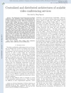
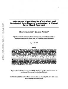
Two grid topologies of equal overall capacities are analyzed. In the first case we consider a system with centralized PV panels and batteries that distributes the energy to the 20 homes (Fig. 1 - centralized microgrid). This approach could be comparable to a megasolar-type microgrid with central energy storage system (ESS) and distributed loads. In the second case we consider 20 standalone home systems with roof-top PV panels and batteries (Fig. 1 - distributed standalone nanogrids). This kind of home energy system is now being commercialized in many countries and can be bought by individuals as an investment towards reducing their own electricity bill. The centralized-resource approach usually requires up-front planning and management as well as high initial investments, but it can be very well optimized for the customers’ needs. When resources (PV and batteries) are managed centrally, the local demand fluctuations can be spread over 20 houses and significantly more of the overall demand energy can be replaced by solar generated energy. On the other hand, the distributed approach has as structural advantages as it can be built bottom up by individuals who decide to invest in a home system (does not require any central coordination). It is also inherently robust against grid related failures. A. Simulation data and set-up We compare both topologies by considering the communitywide generation and storage capacity as variables. We extracted at random 20 households’ annual electricity demand data from a demand database of 100 houses in Kyushu, Japan, all with a standard electricity subscription, that is, a 6kV A pay-as-you-go deal (Fig. 2). For
Fig. 1. Comparison of microgrid topologies
solar irradiation we used NEDO’s irradiation database (http://app7.infoc.nedo.go.jp/index.html) for Naha, Okinawa, Japan. We simulated the overall demand energy that could be replaced by solar energy depending on a given battery capacity and PV size. The Solar Replacement Ratio (SRR) is an indicator that expresses the percentage of electricity demand that could be replaced by solar energy (see equation 1). This indicator can also be interpreted as the energy self-sufficiency of the system.
SRR
=
EDemand − EAC − ESOC EDemand
(1)
For this analysis we assumed a usable battery charge cycle from 30% to 100% of the capacity. Whenever the battery’s SOC is below 30%, AC power from the utility power is used to cover the demand and avoid discharging the battery further. The difference between PV generated energy and consumption is used to charge or discharge the battery. We do not consider conversion, transmission or stand-by losses. In the first case, the electricity demand of 20 houses is summed to form the community’ electricity demand. We ran the algorithm for a total PV size from 40 to 320KWpeak and a total battery size from 60KW h to 580KW h. In the second case, the algorithm is applied for each house’s demand data separately using 1/20th of the capacities for each house, that is, a PV size from 2 to 16KWpeak and batteries from 3KW h to 29KW h.
Fig. 2. Annual Electricity demand and solar irradiation for a solar panel of 3KWpeak
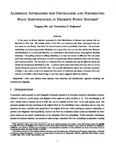
B. Self-sufficiency per topology depending on PV and battery capacity We computed the amount of electricity demand that could be replaced by solar energy using both topologies in function of various system configurations, that is, combinations of PV and battery capacities (see SRR in Fig. 3 a and b). As expected, the single microgrid with shared solar panels and batteries achieves a higher SRR than the standalone nanogrids because local electricity demand fluctuations are better absorbed. Indeed, standalone nanogrids are strongly exposed to both weather fluctuations and electricity demand fluctuations so that even with very high capacity batteries and PV panels it is difficult to reach a SRR higher than 90%. .
Fig. 3. Solar Replacement Ratio for a community of 20 houses throughout one year. a) All batteries and solar panels are shared. b) All batteries and solar panels are distributed in the houses without interconnections
Also, it can be noted that standalone nanogrids start stagnating at around 85% of SRR, while centralized microgrids can reach up to 95%.
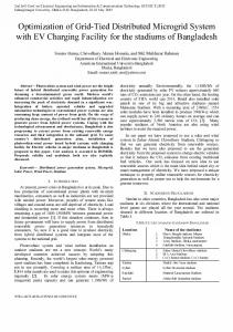
C. Comparison of topologies using of solar replacement energy Finally, we computed the relative difference between the topologies 4: The difference of the annual solar replacement energy in kWh of both topologies divided by the total annual demand in kWh. This gives an indicator similar to the Solar Replacement Ratio corresponding to the percentage of increased self-sufficiency between the topologies. When considering a PV size smaller than 4kWpeak , the demand greatly exceeds generation and thus all generated energy is consumed locally. Generally this can be observed for smaller systems aiming at a self-sufficiency of less than 50% where the topological difference remains rather small (70%), the grid topology can impact the solar replacement to over 10%. For systems with a SRR of above 85% the topological difference decreases again because even standalone systems are big enough to cover most of their own demand electricity. However, in this case the additional investment in batteries or PV needed to increase the SOR further is hard to justify the small increase of SRR.
Fig. 4. Relative difference of electricity demand covered by solar for both cases, standalone nanogrids and single microgrid
D. Discussion In practice, however, SRR is only one of many factors that should be taken into account. Standalone systems are technologically simpler, significantly easier to install and often the only way to set up a energy system. The inherent robustness, local confinement and minimal regulatory barriers pushes these kind of bottom-up home energy systems (or nanogrids) into the market and recently they are starting to experience substantial deployment [6]. They are considered especially
well suited for off-grid areas and with a clear preference for DC solutions [6]. However, currently most microgrids/nanogrids include a utility grid connection in order to prevent outages and avoid wasting generated electricity. On the other hand, feed-in-tariffs (FIT) continue to drop due to the intermittency of power sources and the sequential higher is the costs for upgrading the conventional grid and including energy storage [11]. Even though investment in storage has not yet reach grid parity, energy storage prices are decreasing yearly [5] making it an attractive way of improving the SRR as seen in the Fig. 3. For instance, when the battery size per house is fixed to 5kW h, we can see that an additional 3kWpeak of solar panels on each house would be required to reach the same solar replacement as for the single microgrid topology (see Fig. 5). In other words, this corresponds to about 7000kW h per year of electricity savings. At the current electricity price of about $0.26/kWh in Japan (average price for 2011, Source: IEA, EIA, national electricity boards OANDA), this could theoretically amount to around $1800 of savings per year for the community, which does not quite cover the investment cost of the additional solar panes required. Note that in practice, distribution losses and conversion losses must also be taken into account.
III. O PEN E NERGY S YSTEMS APPROACH The discussion in the previous paragraph led us to develop a third hybrid topology that consists in a 2-layered microgrid that consists in interconnecting the standalone nanogrids that can exchange energy with each other to spread local fluctuations. The idea is to preserve the structural advantages and bottom up approach that standalone nanogrids show, but to be able to exchange with neighbors using dedicated power lines and thus to achieve an SRR closer to the single microgrid approach. This third topology can be seen as an Open Energy System (OES). We have proposed one possible implementation OES as follows (main structure is shown in Fig. 6): Every house is equipped with DC nanogrids including batteries, energy source (i.e. PV panel) and loads constitute the basic standalone subsystems. Subsystems are then interconnected over a DC power bus with neighbors to form a community-wide DC microgrid. Bidirectional DCDC converters that can be used either in current regulated or voltage regulated mode serve as the interface between subsystems: they allow actively controlling power flow and making abstraction of the internal subsystem design as for instance internal bus voltage. In this way, DC power can be exchanged within a community, therefore help balancing demand-response requirements and thus increase self-sufficiency
Fig. 6. Main architecture of Open Energy Systems (OES)
A. Simulation results and evaluation Fig. 5. Comparison for a fixed battery size of 5kWh per house
Since this difference in the topologies is due entirely to the absorption of different consumption patterns of the 20 households, it is strongly affected by outliers: vacant houses, untypical consumption pattern (daily or annual) strongly influence comparison. The more heterogeneous the demand patterns, the bigger the topological difference. Also, in this study we only use solar energy as a source, meaning that generation is exactly the same for all households. However, it could also be possible to have some of the households use a standalone microgrid including a on wind turbine or a bio-fuel generator. Considering all household have access to all resources would then make an even bigger difference.
For managing the demand-response, we implemented an autonomous energy exchange algorithm based on the State of Charge (SOC) of each battery: depending on predefined trigger levels, energy will be automatically sent to neighbors and thus battery are leveled similarly to the centralized approach. Using the same input data as in the previous data, we first simulated the different types of systems, this time using real-time, multi-domain simulations in MATLAB/Simulink/SimScape (more details and results can be found in a related paper). We compare this time SRR for each month of the year. Both previously described systems (standalone nanogrids and one, centralized microgrid) were simulated, as well as the OES system with the autonomous exchange algorithm. For reference, we also show the direct PV system, that is, a system without storage (solar only). We used battery capacities of 6kWh and PV panel with 3kWp. This system takes into account DCDC conversion losses and
line transmission losses. It assumes that the batteries capacities can be used fully. Fig. 7 shows that the OES approach can outperform the standalone nanogrid topology without requiring any additional PV or battery capacity. Of course, this system requires additional investment for the interconnections (DCDC converter, bus lines and controller).
Fig. 8. Control flow chart of Open Energy Systems
Fig. 7. Grid system comparison throughout the year - using 3kWp PV panels and 6kWh batteries in each household
B. Feasibility and implementation The feasibility of this concept has been tested on at our full-scale platform at the Okinawa Institute of Science and Technology where 19 inhabited houses are equipped with nanogrids that are interconnected with a DC power bus line. A distributed and layered software architecture allows to have plug-and-play like flexibility in terms of system size. The energy exchange deals are negotiated between the houses based on battery SOC levels: Depending on the battery SOC level each house can request or respond to energy deals. For instance, if one nanogrid’s SOC level exceeds 90%, it will ask neighboring units if their batteries can store the energy generated by its solar panels. Similarly, if the SOC level drops below a certain predefined level, the unit will request neighbors whose battery level is still sufficiently high. The control logic is freely based on a multi-agent approach as shown in the flowchart shown in 8. For more details on the configuration/setup, the actual execution or regulation of the power please refer to [12]. The first implementation of this autonomous algorithm on the real system have been demonstrated successfully at the second International Symposium of Open Energy Systems in 2-3 February 2015 [13]. Multiple parallel exchange deals were automatically agreed on subsequently executed. Numerical evaluation of the efficiency is not been made available yet. IV. C ONCLUSION In this paper we provide a theoretical categorization and qualitative comparison of grid topologies. Using real electricity demand and solar irradiation data we compared two topologies in function of both PV size and battery capacities using the Solar Replacement Ratio. We obtained a quantitative
Fig. 9. Ongoing feasibility study of Open Energy Systems in Okinawa
measure of the amount of electricity demand covered by solar that then can be translated in energy savings. Even though conversion and distribution losses are not taken into account, it allows to compare the impact on solar energy usage for centralized and distributed microgrids in function of PV and battery capacity. A brief qualitative discussion on the grid system features is provided. Further, we present a hybrid grid system that interconnects standalone nanogrids to one microgrid in which energy is exchanged via an automatic exchange algorithm. The previously obtained results can be seen as theoretical upper limit of efficiency of the exchange algorithm for given different hardware (PV and batteries) configurations. We show that selfsufficiency can be improved by interconnecting standalone microgrids and thus conserving the advantages of the bottomup approach. This study considers homogenous home systems with same PV and battery capacities in all homes and electricity demand taken from consumers with same utility subscription. However,
the topological differences will increase with the heterogeneity of the systems, which is expected to further drive incentives for interconnecting and sharing electricity bottom-up, even in a local community. ACKNOWLEDGMENT This research is partially supported by the “Subtropical and Island Energy Infrastructure Technology Research Subsidy Program” of the Okinawa Prefectural Government and carried out by the research consortium of Sony Computer Science Laboratories, Inc., Okisoukou Co. Ltd., Sony Business Operations Inc. and OIST. R EFERENCES [1] H. Farhangi, “The path of the smart grid,” IEEE Power and Energy Magazine, vol. 8, pp. 18–28, Jan. 2010. [2] P. Khayyer and U. Ozguner, “Decentralized Control of Large-Scale Storage-Based Renewable Energy Systems,” IEEE Transactions on Smart Grid, vol. 5, pp. 1300–1307, May 2014. [3] R. Alford, M. Dean, P. Hoontrakul, and P. Smith, “Power Systems of the Future: The case for energy sotrage, distributed generation, and microgrids,” Tech. Rep. November, Report sponsored by IEEE Smart Grid, with analysis by Zpryme, 2012. [4] The SGMM Team, “SGMM Model Definition,” tech. rep., Carnegy Mellon, 2011. [5] J. J. Justo, F. Mwasilu, J. Lee, and J.-W. Jung, “AC-microgrids versus DC-microgrids with distributed energy resources: A review,” Renewable and Sustainable Energy Reviews, vol. 24, pp. 387–405, Aug. 2013. [6] P. Asmus and M. Lawrence, “Nanogrids,” tech. rep., Navigant Research, 2014. [7] J. K. Kok, M. J. J. Scheepers, and I. G. Kamphuis, “Intelligence in Electricity Networks for Embedding Renewables and Distributed Generation,” Intelligent Infrastructures, vol. 42, no. Intelligent Systems, Control and Automation: Science and Engineering, pp. 179–209, 2010. [8] J. Lopes, A. Madureira, N. Gil, and F. Resende, “Operation of Multi Microgrids,” in Microgrids: Architectures and Control, no. Cam C, ch. Operation, John Wiley & Sons, Ltd., 2014. [9] P. Asmus and M. Lawrence, “Direct Current Distribution Networks,” tech. rep., Navigant Research, 2013. [10] P. Asmus and M. Lawrence, “Virtual Power Plants Demand,” tech. rep., Navigant Research, 2014. [11] R. Gross and T. Green, “The Costs and Impacts of Intermittency :,” tech. rep., Technology and Policy Assessment Function of the UK Energy Research Centre, 2006. [12] A. Werth, N. Kitamura, and K. Tanaka, “Control scheme for sistributed n-to-n power excahnge between solar systems including batteries,” in Going Green - Care Innovation, 2014. [13] M. Tokoro, “DCOES: DC-Based Bottom-Up Energy Exchange System for Community Grid,” in 2nd International Symposium on Open Energy Systems, pp. 22–29, 2015.