Jan 18, 2011 - Correct-by-construction Component-based Systems by .... 1.1 Les Défis de la Construction Correct de Syst`emes `a base de Composants . . 23.
Centralized and Distributed Implementations of Correct-by-construction Component-based Systems by using Source-to-source Transformations in BIP Mohamad Jaber
To cite this version: Mohamad Jaber. Centralized and Distributed Implementations of Correct-by-construction Component-based Systems by using Source-to-source Transformations in BIP. Computer Science [cs]. Universit´e Joseph-Fourier - Grenoble I, 2010. English.
HAL Id: tel-00531082 https://tel.archives-ouvertes.fr/tel-00531082v2 Submitted on 18 Jan 2011
HAL is a multi-disciplinary open access archive for the deposit and dissemination of scientific research documents, whether they are published or not. The documents may come from teaching and research institutions in France or abroad, or from public or private research centers.
L’archive ouverte pluridisciplinaire HAL, est destin´ee au d´epˆot et `a la diffusion de documents scientifiques de niveau recherche, publi´es ou non, ´emanant des ´etablissements d’enseignement et de recherche fran¸cais ou ´etrangers, des laboratoires publics ou priv´es.
THESE Pour obtenir le grade de ´ DE GRENOBLE DOCTEUR DE L’UNIVERSITE Sp´ecialit´e : Informatique Arrˆet´e minist´eriel : 7 aoˆ ut 2006 Pr´esent´ee et soutenue publiquement par Mohamad JABER le 28 Octobre 2010
Impl´ementations Centralis´ee et R´epartie de Syst`emes Corrects par construction a` base des Composants par Transformations Source-`a-source dans BIP Centralized and Distributed Implementations of Correct-by-construction Component-based Systems by using Source-to-source Transformations in BIP Directeur de Th`ese Co-Directeur de Th`ese
Joseph Sifakis Jean-Claude Fernandez
JURY M. M. M. M. M. M.
Jean-Paul Bodeveix Jean-Claude Fernandez Michel Raynal Joseph Sifakis Jean-Bernard STEFANI Janos Sztipanovits
Professeur `a l’Universit´e Paul Sabatier Professeur `a l’Universit´e de Grenoble Professeur `a l’Universit´e de Rennes I Directeur de Recherche au CNRS Directeur de Recherche `a l’INRIA Professeur `a l’Universit´e de Vanderbilt
Examinateur Co-Directeur de Th`ese Rapporteur Directeur de Th`ese Pr´esident Rapporteur
Th`ese pr´epar´ee au sein du Laboratoire VERIMAG dans l’Ecole Doctorale EDMSTII
Thesis
2
Mohamad Jaber
Acknowledgements I wish to express my thanks to Professor Jean-Paul Bodeveix, Professor Michel Raynal, Professor Jean-Bernard Stefani, Professor Janos Sztipanovits for accepting to be members of my jury and for their valuable remarks and comments on my thesis. My greatest thank to my advisors, Professor Joseph Sifakis and Professor Jean-Claude Fernandez, for offering me technical and moral support during my Ph.D. program. They were always there, always patient to listen, to answer and to give advice. I have learnt a lot from their knowledge, their creative minds and their excellent guidance. They taught me not only the knowledge but also the different ways to think, to approach, to analyse and to solve a new problem. Thanks for being great advisors. Special thanks to Doctor Marius Bozga, Doctor Borzoo Bonakdarpour and Jean Quilbeuf for helping me a lot on both theory and implementation. Their intelligence, their enthusiasm always made my difficult problems simple and interesting. It has been a great pleasure to work with them. I’m pleased to have NGUYEN Thanh Hung as my colleague and as my friend. Although we did not work on the same topic but the discussions with him were always helpful and enjoyable. (Sint Chaw, khwe khon, khon khwe). Thanks people in Verimag, especially in BIP group Andreas, Marc, Jacques, Simon, Sophie, Tesnim, Vaso, Matthieu, Yassin for useful exchanges, and all other colleagues for useful seminars. Thanks Imen, Artur, Olivier, Paraskevas, Emmanuel, Rajarshi for many memorable get-togethers. I would like to thanks all the members of Verimag who created such a nice atmosphere in the lab. Special thank also for my friend and my colleague Ylies Falcone. It has been a great pleasure to know my Lebanese friends in Grenoble. Thanks to them, especially Hassan Abbass, Jawad, Ftouni, Louay, Hussein Joumaa, Hassan Bazzi, Ozeir, Mohamad Ghassani, Ali Tahini, Doctor Jalal, Mo2nes, Ghadban, Ibrahim Safeydine, Bachir Aoun, Mohamad Jahjah, Mohamad/Moussa Barakat, . . . Special thanks to my wife to my family, my parents, my sisters, my brother, my aunts, who are always beside me, support me, help me in every possible way. Without them, nothing would have been possible.
Verimag - 28 October 2010
3
Mohamad Jaber
Thesis
4
Mohamad Jaber
To my parents & Roukaya . . .
Verimag - 28 October 2010
5
Mohamad Jaber
Thesis
6
Mohamad Jaber
Centralized and Distributed Implementations of Correct-by-construction Component-based Systems by using Source-to-source Transformations in BIP Abstract The thesis studies theory and methods for generating automatically centralized and distributed implementations from a high-level model of an application software in BIP. BIP (Behavior, Interaction, Priority) is a component framework with formal operational semantics. Coordination between components is achieved by using multiparty interactions and dynamic priorities for scheduling interactions. A key idea is to use a set of correct source-to-source transformations preserving the functional properties of a given application software. By application of these transformations we can generate a full range of implementations from centralized to fully distributed. Centralized Implementation: the implementation method transforms the interactions of an application software described in BIP and generates a functionally equivalent program. The method is based on the successive application of three types of source-to-source transformations: flattening of components, flattening of connectors and composition of atomic components. We shown that the system of the transformations is confluent and terminates. By exhaustive application of the transformations, any BIP component can be transformed into an equivalent monolithic component. From this component, efficient standalone C++ code can be generated. Distributed Implementation: the implementation method transforms an application software described in BIP for a given partition of its interactions, into a Send/Receive BIP model. Send/Receive BIP models consist of components coordinated by using asynchronous message passing (Send/Receive primitives). The method leads to 3-layer architectures. The bottom layer includes the components of the application software where atomic strong synchronization is implemented by sequences of Send/Receive primitives. The second layer includes a set of interaction protocols. Each protocol handles the interactions of a class of the given partition. The third layer implements a conflict resolution protocol used to resolve conflicts between conflicting interactions of the second layer. Depending on the given partition, the execution of obtained Send/Receive BIP model range from centralized (all interactions in the same class) to fully distributed (each class has a single interaction). From Send/Receive BIP models and a given mapping of their components on a platform providing Send/Receive primitives, an implementation is automatically generated. For each class of the partition we generate C++ code implementing the global behavior of its components. The transformations have been fully implemented and integrated into BIP tool-set. The experimental results on non trivial examples and case studies show the novelty and the efficiency of our approach. Key words: Component-based modeling, source-to-source transformation, correct-byconstruction, distributed systems, optimization for performance.
Verimag - 28 October 2010
7
Mohamad Jaber
Thesis
8
Mohamad Jaber
Impl´ementations Centralis´ee et R´epartie de Syst`emes Corrects par construction a` base des Composants par Transformations Source-`a-source dans BIP
R´ esum´ e La th`ese ´etudie la th´eorie et les m´ethodes qui permettent de g´en´erer automatiquement des impl´ementations efficaces tant centralis´ees que distribu´ees `a partir d’une langage de description de haut niveau pour les applications logicielles embarqu´ees. Ce langage (mod`ele) appel´e BIP (un acronyme pour Behavior, Interaction, Priority) est un outil de d´eveloppement logiciel fond´e sur une th´eorie saine qui permet la composition incr´ementale de composants h´et´erog`enes, ainsi que la g´en´eration de code. Une coordination entre les composantes est r´ealis´ee en utilisant des interactions multiparties et des priorit´es dynamiques pour planifier les interactions. L’id´ee de base consiste `a utiliser un ensemble de transformations source`a-source correctes en pr´eservant les propri´et´es fonctionnelles de l’application logiciel. En appliquant ces transformations, nous pouvons g´en´erer une gamme des impl´ementations centralis´ees, partiellement distribu´ees et enti`erement distribu´ees. Impl´ementations Centralis´ees: la m´ethode transforme les interactions d’un logiciel d´ecrit dans BIP et g´en`ere un programme ´equivalent au niveau fonctionnel. La m´ethode est bas´ee sur l’application successive de trois types de transformations source-`a-source: aplatissement des composants, aplatissement des connecteurs et la composition des composants. On a montr´e que le syst`eme des transformations est confluent et se termine. Par une application exhaustive de ces transformations, un composant BIP peut ˆetre transform´e en un composant atomique. A partir de ce composant, un code C++ efficace peut ˆetre g´en´er´e. Impl´ementations Distribu´ees: Pour une partition donn´ee des interactions la m´ethode transforme un application logiciel d´ecrit en BIP, en un mod`ele Send/Receive BIP. Ce mod`ele BIP est constitu´e des composants coordonn´es `a l’aide des messages asynchrones (Send/Receive). La m´ethode conduit `a une architecture de 3-couches. La couche inf´erieure comprend les composants du logiciel o` u les fortes synchronisations atomiques sont impl´ement´ees par des s´equences des primitives Send/Receive. La deuxi`eme couche comprend un ensemble de protocoles d’interaction. Chaque protocole g`ere un ensemble des interactions. La troisi`eme couche impl´emente un protocole de r´esolution des conflits utilis´ees pour r´esoudre les conflits entre les interactions conflictuelles de la deuxi`eme couche. A partir des mod`eles Send/Receive BIP, une impl´ementation C++ est g´en´er´ee automatiquement. Les transformations ont ´et´e impl´ement´ees et int´egr´ees dans la chaˆıne d’outil BIP. Les r´esultats exp´erimentaux sur des exemples non triviaux et des ´etudes de cas montrent la nouveaut´e et l’efficacit´e de notre approche. Mots cl´e: Mod´elisation ` a base de composants, source-`a-source transformation, correctepar-construction, syst`emes distribu´ees, optimisation pour la performance.
Verimag - 28 October 2010
9
Mohamad Jaber
Thesis
10
Mohamad Jaber
Associated Papers
Several Chapters in this thesis appeared in several papers in form of articles or of Verimag technical reports. The symbolic implementation of BIP engine in Chapter 3 appeared in the paper [JBB09] in ICE 2009 (Structured Interactions CONCUR 2009 affiliated workshop), 31st August Bologna, Italy. A journal version is under review in Mathematical Structures in Computer Science. The architecture transformation for performance optimization method in Chapter 4 appeared in the paper [BJS09] in SIES 2009 (IEEE Symposium on Industrial Embedded Systems, Ecole Polytechnique F´ed´erale de Lausanne, Switzerland, July 8 - 10, 2009). A journal version is under review in IEEE Transactions on Industrial Informatics. The BIP into Distributed BIP methods together with the results in Chapter 5 appeared in two papers: paper [BBJ+ 10a] has been accepted (best paper award) for SIES 2010 (IEEE Symposium on Industrial Embedded Systems, University of Trento, Italy, July 7 - 9, 2010), and paper [BBJ+ 10b] has been accepted for EMSOFT 2010 (International Conference on Embedded Software, Scottsdale, Arizona, USA , October 24 - 29, 2010).
11
Thesis
12
Mohamad Jaber
Contents
1 Introduction en Fran¸ cais 1.1 Les D´efis de la Construction Correct de Syst`emes `a base de Composants . . ´ 1.2 Etat de l’art de Conception et Impl´ementation de Syst`emes `a base des Composants . . . . . . . . . . . . . . . . . . . . . . . . . . . . . . . . . . . . . . 1.2.1 Les cadres ` a base de composants . . . . . . . . . . . . . . . . . . . . 1.3 R´esum´e Chapitres . . . . . . . . . . . . . . . . . . . . . . . . . . . . . . . . 1.3.1 Chapitre 2 - BIP Cadre `a Base des Composants . . . . . . . . . . . . 1.3.2 Chapitre 3 - Transformation pour la G´en´eration des Impl´ementation Centralis´ees . . . . . . . . . . . . . . . . . . . . . . . . . . . . . . . . 1.3.3 Chapitre 4 - Transformation pour la G´en´eration des Impl´ementation Distribu´ees . . . . . . . . . . . . . . . . . . . . . . . . . . . . . . . . 1.3.4 Chapitre 5 - Chaˆıne d’outils . . . . . . . . . . . . . . . . . . . . . . . 1.3.5 Chapitre 6 - Conclusions et Perspectives . . . . . . . . . . . . . . . .
23 23
2 Introduction 2.1 Challenges in Building Correct Component-based Systems . . . . . . . . . 2.2 State-of-the-Art of Component-based Systems Design and Implementation 2.2.1 Existing component-based frameworks . . . . . . . . . . . . . . . . 2.2.2 Discussion . . . . . . . . . . . . . . . . . . . . . . . . . . . . . . . . 2.3 Our Contribution . . . . . . . . . . . . . . . . . . . . . . . . . . . . . . . . 2.4 Organization of the Thesis . . . . . . . . . . . . . . . . . . . . . . . . . . .
. . . . . .
31 31 34 34 36 37 38
3 The BIP Component-based Framework 3.1 General Overview . . . . . . . . . . . . . . . . . . . . . . . . . . . . . . . . . 3.2 The BIP Language . . . . . . . . . . . . . . . . . . . . . . . . . . . . . . . .
41 42 43
13
26 26 27 27 28 28 28 29
Contents
3.3
3.4 3.5
3.2.1 Ports and Interfaces . . . . 3.2.2 Atomic Component . . . . 3.2.3 Connectors and Interactions 3.2.4 Priorities . . . . . . . . . . 3.2.5 Composite Components . . Execution Platform . . . . . . . . . 3.3.1 Enumerative Engine . . . . 3.3.2 Symbolic Engine . . . . . . The BIP Tool-Chain . . . . . . . . Summary . . . . . . . . . . . . . .
. . . . . . . . . .
. . . . . . . . . .
. . . . . . . . . .
. . . . . . . . . .
. . . . . . . . . .
4 Transformation for Generating Centralized 4.1 Problem Statement . . . . . . . . . . . . . . 4.2 Transformations . . . . . . . . . . . . . . . 4.2.1 Components Flattening . . . . . . . 4.2.2 Connectors Flattening . . . . . . . . 4.2.3 Components Composition . . . . . . 4.3 Efficient Sequential Implementation . . . . 4.4 Experimental Validation . . . . . . . . . . . 4.4.1 MPEG Video Encoder . . . . . . . . 4.4.2 Concurrent Sorting . . . . . . . . . . 4.5 Summary . . . . . . . . . . . . . . . . . . .
. . . . . . . . . .
. . . . . . . . . .
. . . . . . . . . .
. . . . . . . . . .
. . . . . . . . . .
. . . . . . . . . .
. . . . . . . . . .
. . . . . . . . . .
. . . . . . . . . .
. . . . . . . . . .
. . . . . . . . . .
. . . . . . . . . .
Implementations . . . . . . . . . . . . . . . . . . . . . . . . . . . . . . . . . . . . . . . . . . . . . . . . . . . . . . . . . . . . . . . . . . . . . . . . . . . . . . . . . . . . . . . . . . . . . . . . . . . . . . . . . . . . . . . . . . . . . . . .
. . . . . . . . . .
. . . . . . . . . .
. . . . . . . . . .
. . . . . . . . . .
. . . . . . . . . .
. . . . . . . . . .
. . . . . . . . . .
. . . . . . . . . .
. . . . . . . . . .
. . . . . . . . . .
. . . . . . . . . .
44 45 47 51 52 54 55 55 55 57
. . . . . . . . . .
59 59 60 61 62 66 68 68 68 70 75
5 Transformation for Generating Distributed Implementations 5.1 Problem Statement . . . . . . . . . . . . . . . . . . . . . . . . . . . . . . . . 5.2 Original BIP Model . . . . . . . . . . . . . . . . . . . . . . . . . . . . . . . 5.3 Conflicting Interactions . . . . . . . . . . . . . . . . . . . . . . . . . . . . . 5.4 Proposed Solution . . . . . . . . . . . . . . . . . . . . . . . . . . . . . . . . 5.5 The 3-Layer Architecture . . . . . . . . . . . . . . . . . . . . . . . . . . . . 5.6 Transformations . . . . . . . . . . . . . . . . . . . . . . . . . . . . . . . . . 5.6.1 Transformation of Atomic Components . . . . . . . . . . . . . . . . 5.6.2 The Interaction Protocol . . . . . . . . . . . . . . . . . . . . . . . . . 5.6.3 The Conflict Resolution Protocol . . . . . . . . . . . . . . . . . . . . 5.6.3.1 Centralized Implementation . . . . . . . . . . . . . . . . . . 5.6.3.2 Token Ring Implementation . . . . . . . . . . . . . . . . . 5.6.3.3 Implementation Based on Dining Philosophers . . . . . . . 5.6.4 Cross-Layer Interactions . . . . . . . . . . . . . . . . . . . . . . . . . 5.7 Correctness . . . . . . . . . . . . . . . . . . . . . . . . . . . . . . . . . . . . 5.7.1 Compliance with Send/Receive Models . . . . . . . . . . . . . . . . . 5.7.2 Observational Equivalence between Original and Transformed BIP Models . . . . . . . . . . . . . . . . . . . . . . . . . . . . . . . . . .
Thesis
14
77 78 79 79 83 85 86 86 87 91 92 93 93 93 96 96 97
Mohamad Jaber
Contents 5.7.3 Interoperability of Conflict Resolution Protocol 5.8 Transformation from Send/Receive BIP into C++ . . 5.9 Component Composition . . . . . . . . . . . . . . . . . 5.10 Experimental Validation . . . . . . . . . . . . . . . . . 5.10.1 Diffusing Computation . . . . . . . . . . . . . . 5.10.2 Utopar Transportation System . . . . . . . . . 5.10.3 Bitonic Sorting . . . . . . . . . . . . . . . . . . 5.11 Summary . . . . . . . . . . . . . . . . . . . . . . . . .
. . . . . . . .
. . . . . . . .
. . . . . . . .
. . . . . . . .
. . . . . . . .
. . . . . . . .
. . . . . . . .
. . . . . . . .
. . . . . . . .
. . . . . . . .
. . . . . . . .
. . . . . . . .
100 101 103 103 104 107 112 115
6 Tool-Chain 117 6.1 BIP into Centralized Implementations Tool-Chain - BIP2BIP . . . . . . . . 117 6.2 BIP into Distributed Implementations Tool-Chain - BIP2Dist . . . . . . . . 119 6.3 Summary . . . . . . . . . . . . . . . . . . . . . . . . . . . . . . . . . . . . . 119 7 Conclusions and Perspectives 123 7.1 Conclusions . . . . . . . . . . . . . . . . . . . . . . . . . . . . . . . . . . . . 123 7.2 Perspectives . . . . . . . . . . . . . . . . . . . . . . . . . . . . . . . . . . . . 125
Verimag - 28 October 2010
15
Mohamad Jaber
Contents
Thesis
16
Mohamad Jaber
List of Figures
2.1
High-level component-based design into implementation. . . . . . . . . . . .
33
3.1 3.2 3.3 3.4 3.5 3.6 3.7 3.8 3.9 3.10 3.11 3.12 3.13 3.14
Components composition. . . . . . . . . . . . . . . . . . . . . Incrementality of composition. . . . . . . . . . . . . . . . . . Compositionality of composition. . . . . . . . . . . . . . . . . Composability of composition. . . . . . . . . . . . . . . . . . Layered component model. . . . . . . . . . . . . . . . . . . . Three-dimentional space construction. . . . . . . . . . . . . . An example of an atomic component in BIP. . . . . . . . . . Connectors and their interactions. . . . . . . . . . . . . . . . Graphic representation of connectors . . . . . . . . . . . . . . An example of a connector containing one interaction in BIP. γi dominates γj . . . . . . . . . . . . . . . . . . . . . . . . . . An example of compound component in BIP. . . . . . . . . . Component composition. . . . . . . . . . . . . . . . . . . . . . The BIP tool-chain. . . . . . . . . . . . . . . . . . . . . . . .
. . . . . . . . . . . . . .
. . . . . . . . . . . . . .
. . . . . . . . . . . . . .
. . . . . . . . . . . . . .
. . . . . . . . . . . . . .
. . . . . . . . . . . . . .
. . . . . . . . . . . . . .
. . . . . . . . . . . . . .
42 42 43 43 44 44 46 47 48 49 51 53 54 56
4.1 4.2 4.3 4.4 4.5 4.6 4.7 4.8
Example. . . . . . . . . . . . . . . . . . . . . . . . Component flattening. . . . . . . . . . . . . . . . . Component flattening for example in Figure 4.1. . Connector glueing. . . . . . . . . . . . . . . . . . . Connector glueing for example in Figure 4.3. . . . Connector flattening for example in Figure 4.3. . . Component composition. . . . . . . . . . . . . . . . Component composition for example in Figure 4.6.
. . . . . . . .
. . . . . . . .
. . . . . . . .
. . . . . . . .
. . . . . . . .
. . . . . . . .
. . . . . . . .
. . . . . . . .
61 62 63 63 65 65 67 67
17
. . . . . . . .
. . . . . . . .
. . . . . . . .
. . . . . . . .
. . . . . . . .
. . . . . . . .
List of Figures 4.9 4.10 4.11 4.12 4.13 4.14
MPEG4 encoder structure. . . . . . . . Encode component structure. . . . . . . Execution time for the MPEG4 encoder. Concurrent sorting n = 2. . . . . . . . . Concurrent sorting n = 4. . . . . . . . . Execution time for concurrent sorting. .
. . . . . .
68 69 71 72 72 74
5.1 5.2 5.3 5.4 5.5 5.6 5.7 5.8 5.9 5.10 5.11 5.12
A simple high-level BIP model. . . . . . . . . . . . . . . . . . . . . . . . . . Centralized Engine. . . . . . . . . . . . . . . . . . . . . . . . . . . . . . . . . Violating of BIP semantics when badly distributed interactions. . . . . . . . Conflict interactions. . . . . . . . . . . . . . . . . . . . . . . . . . . . . . . . Drawbacks of conflict-free solution. . . . . . . . . . . . . . . . . . . . . . . . Resolving conflict interactions using alpha-core protocol. . . . . . . . . . . . General overview of the 3-layer architecture. . . . . . . . . . . . . . . . . . . 3-layer Send/Receive BIP model of Figure 5.1. . . . . . . . . . . . . . . . . Transformation of atomic component. . . . . . . . . . . . . . . . . . . . . . Component IP1 in Figure 5.8. . . . . . . . . . . . . . . . . . . . . . . . . . . A centralized Conflict Resolution Protocol for Figure 5.8. . . . . . . . . . . Token-based Conflict Resolution Protocol for the BIP models in Figures 5.1 and 5.8. . . . . . . . . . . . . . . . . . . . . . . . . . . . . . . . . . . . . . . Dining philosophers-based Conflict Resolution Protocol for the BIP models in Figures 5.1 and 5.8. . . . . . . . . . . . . . . . . . . . . . . . . . . . . . . Proof of observational equivalence. . . . . . . . . . . . . . . . . . . . . . . . The impact of merging components. . . . . . . . . . . . . . . . . . . . . . . Partial BIP model for diffusing computations. . . . . . . . . . . . . . . . . . Different scenarios for diffusing computations. . . . . . . . . . . . . . . . . . Performance of termination detection in diffusing computation in different scenarios (Torus 4×6). . . . . . . . . . . . . . . . . . . . . . . . . . . . . . . Performance of termination detection in diffusing computation in different scenarios (Torus 20×20). . . . . . . . . . . . . . . . . . . . . . . . . . . . . . Utopar transportation system. . . . . . . . . . . . . . . . . . . . . . . . . . High-level BIP model for Utopar system. . . . . . . . . . . . . . . . . . . . . Performance of responding 10 requests per calling unit (25 = 5 × 5 calling units, and 4 cars). . . . . . . . . . . . . . . . . . . . . . . . . . . . . . . . . Performance of responding 10 request per calling unit (49 = 7 × 7 calling units, and 4 cars). . . . . . . . . . . . . . . . . . . . . . . . . . . . . . . . . High-level BIP model for Bitonic Sorting Algorithm. . . . . . . . . . . . . . 3-layer Send/Receive BIP model for Bitonic Sorting Algorithm. . . . . . . . Component composition components in Bitonic Sorting 3-layer Send/Receive BIP model. . . . . . . . . . . . . . . . . . . . . . . . . . . . . . . . . .
78 80 81 81 82 83 84 85 87 89 92
5.13 5.14 5.15 5.16 5.17 5.18 5.19 5.20 5.21 5.22 5.23 5.24 5.25 5.26
Thesis
18
. . . . . .
. . . . . .
. . . . . .
. . . . . .
. . . . . .
. . . . . .
. . . . . .
. . . . . .
. . . . . .
. . . . . .
. . . . . .
. . . . . .
. . . . . .
. . . . . .
. . . . . .
. . . . . .
. . . . . .
. . . . . .
. . . . . .
94 95 99 103 105 105 107 108 109 110 111 112 113 113 115
Mohamad Jaber
List of Figures 6.1 6.2 6.3
BIP2BIP toolset: General architecture . . . . . . . . . . . . . . . . . . . . . 118 BIP2Dist toolset: General architecture . . . . . . . . . . . . . . . . . . . . . 120 Design process to automatically generate distributed implementations . . . 121
Verimag - 28 October 2010
19
Mohamad Jaber
List of Figures
Thesis
20
Mohamad Jaber
List of Tables
4.1 4.2
Code size in lines-of-code (loc) for MPEG4 encoder. . . . . . . . . . . . . . Code size in loc for concurrent sorting. . . . . . . . . . . . . . . . . . . . . .
5.1 5.2
Performance of Bitonic Sorting Algorithm. . . . . . . . . . . . . . . . . . . . 114 The impact of component composition on Send/Receive models. . . . . . . 114
21
70 73
List of Tables
Thesis
22
Mohamad Jaber
CHAPTER
1
Introduction en Fran¸cais
Contents 1.1
Les D´ efis de la Construction Correct de Syst` emes ` a base de Composants . . . . . . . . . . . . . . . . . . . . . . . . . . . . . . . ´ 1.2 Etat de l’art de Conception et Impl´ ementation de Syst` emes ` a base des Composants . . . . . . . . . . . . . . . . . . . . . . . . . 1.2.1 Les cadres ` a base de composants . . . . . . . . . . . . . . . . . . . 1.3 R´ esum´ e Chapitres . . . . . . . . . . . . . . . . . . . . . . . . . . . 1.3.1 Chapitre 2 - BIP Cadre `a Base des Composants . . . . . . . . . . . 1.3.2 Chapitre 3 - Transformation pour la G´en´eration des Impl´ementation Centralis´ees . . . . . . . . . . . . . . . . . . . . . . . . . . . . . . . 1.3.3 Chapitre 4 - Transformation pour la G´en´eration des Impl´ementation Distribu´ees . . . . . . . . . . . . . . . . . . . . . . . . . . . . . . . 1.3.4 Chapitre 5 - Chaˆıne d’outils . . . . . . . . . . . . . . . . . . . . . . 1.3.5 Chapitre 6 - Conclusions et Perspectives . . . . . . . . . . . . . . .
1.1
23 26 26 27 27 28 28 28 29
Les D´ efis de la Construction Correct de Syst` emes ` a base de Composants
Les syst`emes informatiques sont omnipr´esents aujourd’hui, ils se touchent tous les aspects de la vie humaine. Nous pouvons les trouver dans diff´erents types des applications de l’automobile, aux appareils m´enagers banals comme les machines `a laver et des fours ` a micro-ondes, ` a l’a´eronautique, militaire, t´el´ecommunications, m´edicaux, . . .
23
Chapter 1. Introduction en Fran¸cais Les syst`emes deviennent de plus en plus complexes et leur adoption est en augmentation exponentielle. En outre, la n´ecessit´e de prouver et de garantir leur validit´e, l’efficacit´e et la fiabilit´e est une tˆ ache essentielle qui est aussi complexes. Bien que diff´erentes techniques de g´enie logiciel existent pour assurer l’exactitude telles que la v´erification formelle, la simulation et les tests, le renforcement des syst`emes justes et fiables est toujours une tˆache difficile. Les erreurs existent encore dans plus de 90% des cahiers de charge de production. En plus, le temps pass´e dans les d´ebogage est tr`es ´elev´e et parfois sans r´esultats ´ satisfaisants. A titre d’exemple, les Etats-Unis a tent´e de remplacer son syst`eme de contrˆole du trafic a´erien trois fois au cours des vingt derni`eres ann´ees, mais malgr´e les milliards de dollars US d´epens´es, tel remplacement ne s’est pas pass´e. Approche Fond´ ee sur les Composants La technique la plus fondamentale pour r´esoudre des probl`emes complexes est de les d´ecomposer en plus petites. Comme les syst`emes complexes peuvent ˆetre obtenus par assemblage de composants (construction des blocs), le processus de conception de ces syst`emes complexes peut ˆetre r´eduite `a l’´etude des plus petits et plus simples composants. Ainsi, en utilisant un tels cadres (appel´e ` a base de composants ) qui permettent la construction des syst`emes `a partir de composants pr´ed´efinis. Le d´eveloppement de syst`emes ` a base de composants n´ecessite des m´ethodes et des outils de diff´erents concepts de l’architecture qui fournissent aussi une caract´erisation de coordination entre les composantes. L’architecture est la structure d’un syst`eme. Il comprend des ´el´ements et leur relation entre les propri´et´es visibles de l’ext´erieur. Cela signifie que l’architecture d´ecrit comment les composants sont connect´es et comment ils peuvent interagir. Par cons´equent, le comportement global d’un syst`eme peut en principe ˆetre d´eduite du comportement de ses composants et son architecture. Les syst`emes `a base de composants fournissent descriptions claires et logiques qui en font un bon candidat pour un processus bas´es sur la construction. En outre, ils permettent la r´eutilisations des soussyst`emes, ainsi que leur modification progressive sans n´ecessiter de changements mondiaux, ce qui peut simplifier consid´erablement le processus de v´erification. N´eanmoins, la clart´e et l’expressivit´e des syst`emes ` a base de composants peut ˆetre au d´etriment de l’efficacit´e. En effet, la compilation na¨ıve de syst`emes `a base de composants se traduit g´en´eralement par l’inefficacit´e comme une cons´equence de l’interconnexion des composants. Conception de Haut Niveau Lors de la conception des syst`emes complexes, le traitement de la complexit´e ` a un haut niveau est d’une grande aide pour les concepteurs. En fait, il serait plus facile pour les concepteurs de commencer `a travailler sur le syst`eme `a un haut niveau, o` u ils n’ont pas ` a tenir compte de la complexit´e du syst`eme. Cet phase de mod´elisation phase de mod´elisation est b´en´efique, car les concepteurs peuvent abstraire des d´etails d’impl´ementation et de valider le mod`ele abstrait par rapport `a un ensemble de prescriptions visant ` a travers diff´erentes techniques telles que la v´erification formelle, la
Thesis
24
Mohamad Jaber
Chapter 1. Introduction en Fran¸cais simulation et les tests. Malheureusement, une fois le mod`ele abstrait est valid´e, la g´en´eration des impl´ementations correcte et efficace est toujours difficile, car ajoutant des d´etails de mise d’impl´ementation implique de nombreuses subtilit´es qui peuvent potentiellement introduire des erreurs dans le syst`eme r´esultant. Impl´ ementation La conception haut niveau est utilis´e pour prototyper et valider de mod`eles complexes. Apr`es cette phase, la conception est g´en´eralement coder par la main pour g´en´erer une impl´ementation du syst`eme. Toutefois, ce processus de traduction est complexe et il peut r´eduire la contribution de la v´erification et de tests effectu´es sur le mod`ele de haut niveau. Par cons´equent, la g´en´eration automatique de code est n´ecessaire et peut fournir un gain de temps important. N´eanmoins, le principal inconv´enient de cette approche automatique est son efficacit´e. En effet, l’efficacit´e d’un code g´en´er´e d´epend en g´en´eral de l’architecture cible. ´ Etant donn´e un mod`ele de haut niveau, l’impl´ementation g´en´er´e peuvent ˆetre, en g´en´eral, centralis´ee ou distribu´ee. Cela d´epend `a la fois de la topologie des syst`emes et l’architecture sur laquelle le syst`eme sera d´eploy´e. Par exemple, si l’on consid`ere un syst`eme centralis´e avec une petite quantit´e de calcul et beaucoup de communication, dans ce cas une impl´ementation centralis´ee se comporte mieux qu’un distribu´es. Dans d’autres cas, nous pourrions avoir `a choisir une impl´ementation distribu´ee parce que le syst`eme lui-mˆeme est r´epartie g´eographiquement, ou parce que l’utilisation des plusieurs processeurs est n´ecessaire pour effectuer un grand puissance de calcul. Une impl´ementation distribu´e est n´ecessaire pour ce genre de syst`emes. Ces syst`emes sont principalement utilis´es pour le monde entier-web, serveur de transfert des fichiers, r´eseau bancaire, les r´eseaux pair-` a-pair, les syst`emes de contrˆole de processus, r´eseaux de capteurs, grille de calcul, etc Il est clair que la complexit´e sont amplifi´es de mani`ere significative dans le cas des impl´ementations distribu´es ` a cause de la structure concurrente, non d´eterministe, et nonatomique de syst`emes distribu´es, ainsi que la survenue d’´ev´enements impr´evus physiques et informatiques telles que les failles. En outre, il est difficile de savoir comment transformer un mod`ele abstrait (o` u atomicit´e est suppos´e par la s´emantique global et les d´etails de distribution ont ´et´e omis tout en employant primitives de synchronisation de haut niveau) en une impl´ementation distribu´es. Dans cette th`ese nous proposons une th´eorie et des outils pour d´eriver automatiquement des impl´ementations centralis´ee et distribu´ee correcte et efficace d’une mani`ere syst´ematique et automatis´e ` a partir d’un cadre de haut niveau `a base de composants. Ce r´esultat est obtenu, en utilisant des techniques de transformations source-`a-source, correcte techniques de construction.
Verimag - 28 October 2010
25
Mohamad Jaber
Chapter 1. Introduction en Fran¸cais
1.2 1.2.1
´ Etat de l’art de Conception et Impl´ ementation de Syst` emes ` a base des Composants Les cadres ` a base de composants
Les techniques de conception ` a base de composants sont utilis´es pour r´eduire la complexit´e des syst`emes. L’id´ee est que les syst`emes complexes peuvent ˆetre obtenus par assemblage de composants. Cela est essentiel pour le d´eveloppement `a grande ´echelle, les syst`emes ´evolutifs d’une mani`ere rapide et abordable. Il offre une flexibilit´e dans la phase de construction des syst`emes en soutenant l’ajout, la suppression ou la modification des composants sans aucune ou tr`es peu d’impact sur les autres composantes. Les composants sont g´en´eralement caract´eris´es par des abstractions qui ignorent les d´etails d’impl´ementation et de d´ecrire les propri´et´es pertinentes de leur composition, par exemple fonctions de transfert, interfaces. La principale caract´eristique de cadres de conception `a base de composants est la composition. La composition est utilis´ee pour construire des composants complexes ` a partir de plus simples. Il peut ˆetre formalis´e par une op´eration qui prend en entr´ee un ensemble de composants et de leurs contraintes d’int´egration et fournit, en sortie, la description d’un nouveau composant plus complexe. Cette approche permet de r´eduire la complexit´e des syst`emes en offrant l’effet d’accroissement dans la phase de construction. Il existe une grande litt´erature traitant la conception `a base de composants. Les travails suivants sont li´es ` a cette approche: – PtolemyII est un cadre logiciel, d´evelopp´e au g´enie ´electrique et informatique (RECS) UC Universit´e de Berkeley. PtolemyII porte sur la mod´elisation h´et´erog`enes `a base de composants. Il pr´econise une vision ax´ee sur les acteurs d’un syst`eme, o` u le bloc de construction de base d’un syst`eme est un acteur. Un mod`ele est une interconnexion hi´erarchique des acteurs. Les acteurs sont des composants logiciels qui s’ex´ecutent simultan´ement et se communiquent `a travers des interfaces appel´ees ports. Un acteur peut ˆetre atomique, dans ce cas elle doit ˆetre au bas de la hi´erarchie. Un acteur peut ˆetre composite, dans ce cas, il contient d’autres acteurs. La s´emantique d’un mod`ele n’est pas d´etermin´ee par le cadre, mais plutˆot par un composant logiciel dans le mod`ele appel´e le directeur, qui met en œuvre un mod`ele de calcul. PtolemyII permet la simulation de mod`eles. Toutefois, la v´erification des mod`eles est, actuellement, pas possible. Des travaux sont en cours pour ajouter cette possibilit´e. Il permet la g´en´eration de code, pour ce faire, chaque composant doit ˆetre accompagn´ee d’un mod`ele (�template�) de code C qui sera compl´et´e par le g´en´erateur de code. En outre, PtolemyII n’a pas de notion intrins`eque de mappage entre les acteurs ou de l’utilisation de sp´ecification d´eclarative dans la conception. – IF (Intermediate Format) est un ensemble d’outils, d´evelopp´e `a Verimag. IF est un ensemble d’outils de plateforme de mod´elisation et validation des composants. Il se compose d’ensemble d’automates temporis´e communicants de mani`ere asynchrone en
Thesis
26
Mohamad Jaber
Chapter 1. Introduction en Fran¸cais envoyant des signaux ` a travers FIFO, ou de mani`ere synchrone avec rendez sur les ports synchronis´e. IF utilise des techniques telles que la r´eduction d’ordre partiel et model-cheking ` a la vol´ee pour l’exploration d’espace d’´etat. – Fractal est un mod`ele de composant, d´evelopp´e `a France T´el´ecom R & D et l’INRIA en France. Fractal est un mod`ele de composants g´en´erales, pour le d´eploiement et la gestion de syst`emes logiciels complexes. Il peut ˆetre comprise comme ´etant compos´e d’un membrane qui se compose d’un ensemble de composants (appel´es souscomposants) et une ou plusieurs interfaces (semblable au port de mod`eles de composants d’autres). Les interfaces peuvent ˆetre de deux sortes: les interfaces serveur pour les appels des op´erations entrants, et les interfaces clients pour les appels des op´eration sortants. THINK est l’un des la mise en œuvre de Fractal. Cependant Fractal et THINK ne fournit pas d’outils ou de techniques d’analyse, que ce soit pour la simulation ou de v´erification. – Metropolis est un cadre ` a base de composants: composants atomiques contenant comportement (code), pi`ece en mat´eriau composite contenant d’autres sous-composantes. Interfaces des composants sont constitu´es d’un ensemble de ports utilis´es soit pour les communications asynchrones (envoyer des ´ev´enements), ou pour rendez-vous (synchronisation entre les composants). Metro II fournit une interface qui produit une repr´esentation interne de la m´eta-mod`ele. Cette repr´esentation peut ˆetre utilis´e pour, g´en´eration de code C pour la simulation, ou mod`ele de g´en´eration utilis´e avec le mod`ele de spin-checker, etc. D’autres d´eveloppements traitent, d’une fa¸con ou d’une autre, des questions li´ees `a la mod´elisation bas´ee sur les composants: – langages de mod´elisation de syst`eme tel que UML et les outils associ´es. – langages pour la conception de syst`emes tels que SystemC, GME , Simulink/Stateflow, Autofocus. – normes Middleware tels que Corba, JavaBeans,. NET – les environnements de d´eveloppement logiciels tels que PCTE, SWbus, Softbench, Eclipse. – langage de coordination extension du langage de programmation tels que Linda, JavaSpaces, TSpaces, Concurrent Fortran, le CNES et polyphoniques C] . – cadres th´eoriques bas´es sur les alg`ebres de processus par exemple, le Pi-calcul ou bas´e sur des automates.
1.3 1.3.1
R´ esum´ e Chapitres Chapitre 2 - BIP Cadre ` a Base des Composants
Ce chapitre pr´esente plusieurs notions de base fondamentales pour l’´etude des syst`emes complexes, ` a savoir la m´ethodologie `a base de composants, leur composition fond´ee des
Verimag - 28 October 2010
27
Mohamad Jaber
Chapter 1. Introduction en Fran¸cais op´erateurs ad´equats et bien d´efinis, ainsi que les propri´et´es n´ecessaires `a la construction de syst`emes construits ` a partir de composants. Ce chapitre introduit ensuite le langage BIP (son architecture, sa s´emantique, et ses propri´et´es).
1.3.2
Chapitre 3 - Transformation pour la G´ en´ eration des Impl´ ementation Centralis´ ees
Ce chapitre pr´esente une m´ethode pour g´en´erer des impl´ementations centralis´ees correctes et efficaces ` a partir de programmes BIP. La m´ethode propos´ee est fond´ee sur l’application successive de trois types de transformations source-`a-source: aplatissement des composants, aplatissement des connecteurs, puis composition des composants. L’application successive des ces transformations permet de synth´etiser vers un seul composant (qui est un r´eseau de P´etri). A partir de ce composant un code C efficace est g´en´er´e. Ce chapitre d´ecrit des applications de cette m´ethodes sur des exemples non triviaux (encodage Vid´eo MPEG4, Network Sorting Algorithm).
1.3.3
Chapitre 4 - Transformation pour la G´ en´ eration des Impl´ ementation Distribu´ ees
Ce chapitre d´eveloppe une m´ethode pour g´en´erer des impl´ementations distribu´ees correctes et efficaces ` a partir de programmes BIP. Pour cela il pr´esente d’abord les principales difficult´es rencontr´ees dans la g´en´eration d’impl´ementations distribu´ees. Il d´efinit ensuite un ensemble de transformations source-`a-source qui permettent: – la rupture des atomicit´es des actions dans les composants atomiques en rempla¸cant les synchronisations fortes (rendez-vous) par des interactions asynchrones de type Send/Receive; – la g´en´eration des contrˆ oleurs qui coordonnent l’ex´ecution des interaction selon une partition d´efinie par l’utilisateur; – l’ajout d’un algorithme distribu´e pour le traitement des conflits entre contrˆoleurs. Le mod`ele Send/Receive est prouv´es observationnellment ´equivalents au mod`ele initial. En outre, des impl´ementations distribu´ees peuvent ˆetre g´en´er´ees `a partir de mod`eles Send/Receive qui permettent un parall´elisme r´eel entre les composants ainsi entre les interactions. En particulier, il est possible de g´en´erer des modules autonomes en code C qui utilisent des communications du type MPI ou socket.
1.3.4
Chapitre 5 - Chaˆıne d’outils
Ce chapitre pr´esente les outils qui mettent en œuvre la th´eorie et les transformations d´efinies dans ce travail. Il pr´esente aussi une int´egration de ces outils dans la phase de conception des applications en BIP, dont le but est de g´en´erer des impl´ementations (tant centralis´ees que distribu´ees).
Thesis
28
Mohamad Jaber
Chapter 1. Introduction en Fran¸cais
1.3.5
Chapitre 6 - Conclusions et Perspectives
Ce chapitre fournit une conclusion g´en´erale et des directions de recherche futures. L’une d’entre elles r´eside dans la prise en compte de priorit´es dans les impl´ementations distribu´ees.
Verimag - 28 October 2010
29
Mohamad Jaber
Chapter 1. Introduction en Fran¸cais
Thesis
30
Mohamad Jaber
CHAPTER
2
Introduction
Contents 2.1 2.2
Challenges in Building Correct Component-based Systems . . State-of-the-Art of Component-based Systems Design and Implementation . . . . . . . . . . . . . . . . . . . . . . . . . . . . . . 2.2.1 Existing component-based frameworks . . . . . . . . . . . . . . . . 2.2.2 Discussion . . . . . . . . . . . . . . . . . . . . . . . . . . . . . . . . 2.3 Our Contribution . . . . . . . . . . . . . . . . . . . . . . . . . . . 2.4 Organization of the Thesis . . . . . . . . . . . . . . . . . . . . . .
2.1
31 34 34 36 37 38
Challenges in Building Correct Component-based Systems
Computer systems are ubiquitous today, they are touching all aspects of human life. We can find them in different types of applications from automobile, to mundane home appliances like washing machines and microwave ovens, to aeronautic, military, telecommunication, medical etc. Systems become more and more complex and their adoption is increasing exponentially. Moreover, the need to prove and to ensure their correctness, efficiency and reliability is an essential task that is also becoming complex. Although different techniques in software engineering exist for ensuring correctness such as formal verification, simulation, and testing, building correct and reliable systems is still a time-consuming and hardly predictive task.
31
Chapter 2. Introduction Errors still exist in up to 90% of production spreadsheets. Moreover, the time spent in debugging them is considerably high and sometimes with no satisfying results. As an example, the United States has attempted to replace its air traffic control system three times in the past twenty years, but despite the billions of US dollars spent, no such replacement has happened. Component-based Approach The most basic technique to tackle complex and large problems is to decompose them into smaller ones. As complex systems can be obtained by assembling components (building blocks), the process design of these complex systems may be reduced to the study of smaller and simpler ones. Thus, using such frameworks (called component-based ) that allow building systems from predefined given components would be a great interest. Component-based system development requires methods and tools supporting different concepts of architecture which provide a characterization coordination between components. An architecture is the structure of a system. It involves components and their relationship between the externally visible properties. This means that the architecture describes how components are connected and how they can interact. Consequently, the global behavior of a system can in principle be inferred from the behavior of its components and its architecture. Component-based systems provide logical clear descriptions which make them a good candidate for a correct-by-construction process. In addition, they allow sub-systems to be reused as well as their incremental modification without requiring global changes, which may significantly simplify the verification process. Nonetheless, clarity and expressiveness of component-based systems may be at the detriment of efficiency. Indeed, naive compilation of component-based systems generally results in great inefficiency as a consequence of the interconnection of components [Lov77]. High-Level Design When designing systems, dealing with their complexity at a highlevel is a great help for the designers. In fact, it would be easier for designers to start working on the system at a high-level, where they do not have to take into account the complexity of the system. This modeling phase is beneficial, as designers can abstract away implementation details and validate the model with respect to a set of intended requirements through different techniques such as formal verification, simulation, and testing. Unfortunately, once the abstract model is validated, deriving correct and efficient implementation from it is always challenging, since adding implementation details involves many subtleties that can potentially introduce errors into the resulting system. Implementation Level High-level design is used to prototype and validate new designs. After this phase, the design is typically translated by hand into code for a system implementation. However, this translation process is complex and it may reduce the contribution of the verification and testing done at the high-level model. Therefore, automatic code
Thesis
32
Mohamad Jaber
Chapter 2. Introduction generation is necessary and may provide an important time gain. Nevertheless, the main drawback of this automatic approach is its efficiency. Indeed, the efficiency of a generated code depends in general on the target architecture. Given a high-level model, the implementation generated could be, in general, centralized or distributed. This depends both on the topology of the systems and the architecture on which the system will be deployed. For instance, if we consider a centralized system with a small amount of computation and a high-level of communications overhead, then a centralized implementation behaves better than a distributed one. In other cases, we may have to choose a distributed implementation because the system itself is geographically distributed, or because deriving more computational power by using multiple processors is necessary. These kind of systems where distributed implementation is needed, are mainly used for world-wide-web, network-file server, banking network, peer-to-peer networks, process control systems, sensor networks, grid computing, etc. It is clear the complexity are amplified significantly in the case of deriving distributed implementation because of inherently concurrent, non-deterministic, and non-atomic structure of distributed systems, as well as the occurrence of unanticipated physical and computational events such as faults. Moreover, it is unclear how to transform an abstract model (where atomicity is assumed through global state semantics and distribution details are omitted via employing high-level synchronization primitives) into a real distributed implementation.
A B S T R A C I O N
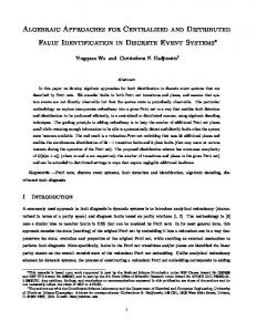
High−level Component−based Design Language
Source−to−Source Transformation Low−level Implementation int f(...) { send(a,b); i++; .... ? }
int f(...) { send(a,b); i++; .... ? }
int f(...) { send(a,b); i++; .... ? }
E F F I C I E N C Y
C O R R E C T N E S S
?
?
Figure 2.1: High-level component-based design into implementation.
Verimag - 28 October 2010
33
Mohamad Jaber
Chapter 2. Introduction In this thesis we propose a theory and tools for automatically derives correct and efficient centralized and distributed implementation in a systematic and ideally automated correct fashion from a high-level component-based framework. This is achieved, by using correctby-construction source-to-source transformations techniques (see Figure 2.1). The rest of the chapter is organised as follows. First in Section 2.2 we give a brief description of the current state of the art of component-based systems design and implementation. Then, in Section 2.3 we present the contribution of the thesis. Finally, we describe the outline of the thesis in Section 2.4.
2.2
State-of-the-Art of Component-based Systems Design and Implementation
In this section we summarize a brief description of the current state-of-the-art in component-based systems.
2.2.1
Existing component-based frameworks
Component-based design techniques are used to cope with the complexity of the systems. The idea is that complex systems can be obtained by assembling components. This is essential for the development of large-scale, evolvable systems in a timely and affordable manner. It offers flexibility in the construction phase of systems by supporting the addition, removal or modification of components without any or very little impact on other components. Components are usually characterized by abstractions that ignore implementation details and describe relevent properties to their composition, e.g. transfer functions, interfaces. The main feature of component-based design frameworks is allowing composition. This composition is used to build complex components from simpler ones. It can be formalized as an operation that takes, as input, a set of components and their integration constraints and provides, as output, the description of a new more complex component. This approach allows to cope with the complexity of systems by offering incrementality in the construction phase. There exists a large body of literature dealing with componentbased design. The following works are related to this approach: – PtolemyII [DII+ 99, EJL+ 03] is a software framework, developed at Electrical Engineering and Computer Sciences (EECS) UC Berkeley University. PtolemyII focuses on component-based heterogeneous modeling. It advocates an actor-oriented view of a system, where the basic building block of a system is an actor. A model is a hierarchical interconnection of actors. Actors are software components that run concurrently and communicate through interfaces called ports. An actor can be atomic, in which case it must be at the bottom of the hierarchy. An actor can be composite, in which case it contains other actors. The semantics of a model is not determined by the framework, but rather than by a software component in the model called di-
Thesis
34
Mohamad Jaber
Chapter 2. Introduction rector, which implements a model of computation. PtolemyII allows the simulation of models. However, the verification of models is, currently, not possible. Work is underway to add this possibility. It allows the generation of code, to do this, each component must be accompanied by a model (”template”) of C code which will be completed by the code generator. Moreover, PtolemyII has no intrinsic notion of mapping between actors or of using declarative specification in the design. – IF (Intermediate Format) [BGO+ 04] is a toolset, developed at Verimag. The IF toolset is a platform for component modeling and validation. It consists of set of timed automata communicating, either asynchronously by sending signals through FIFO, or synchronously with rendez on synchronized ports. The IF toolset uses techniques such as partial order reduction and on-the-fly model checking to explore the state space of the IF specification, giving access at the semantic level, to the corresponding labeled transition system (LTS). The latter can be analysed using the tool suite CADP [FGK+ 96], including the minimization and comparison tool Aldebaran based on bisimulation, and the alternating-free -calculus model-checker Evaluator. – Fractal [BCS02, BCL+ 06] is a component model, developed at France Telecom R&D and INRIA France. Fractal is a general component model for implementing, deploying and managing complex software systems. It can be understood generally as being composed of a membrane which consists of a set of components (called subcomponents) and one or more interfaces (similar to port in other component models). Interfaces can be of two kinds: server interfaces for incoming operation invocations, and client interfaces for outgoing operations invocations. Think [FSLM02, AHJ+ 09] is one of the Fractal implementation. However Fractal and THINK do not provide tools or analysis techniques, whether for simulation or verification. – Metropolis [BWH+ 03] and its successor [DDM+ 07]. Metropolis is a component-based framework : atomic component containing behavior (code), composite component containing other sub-components. Interfaces of components consist of a set of ports used either for asynchronous communications (send events), or for rendez-vous (synchronization between components). Metro II provides a frontend which produces an internal representation from the meta-model. This representation can be used for, generation of C++ code for simulation, or generation model used with the SPIN model-checker, etc. Other developments deal, one way or another, with issues related to component-based modeling: – Software Design Description Languages [GS04, BFL+ 04], and Architecture Description Languages focusing on non-functional aspects [VPL99, AVCL02]. – Standardized system modeling languages such as UML [OMG] and associated tools. – Languages and notations specific to system design tools such as SystemC [Pan01,
Verimag - 28 October 2010
35
Mohamad Jaber
Chapter 2. Introduction
– – –
–
RHG+ 01], GME [BGK+ 06], Simulink/Stateow [Mat], Autofocus [HS02]. Middleware standards such as Corba, Javabeans, .NET Software development environments such as PCTE, SWbus, Softbench, Eclipse. Coordination language extension of programming languages such as Linda, Javaspaces [FAH99], TSpaces [FLN+ 03], Concurrent Fortran, nesC [GLvB+ 03] and Polyphonic C] [BCF02]. Theoretical frameworks based on process algebras e.g., the Pi-Calculus [Mil98] or based on automata e.g., [RC03].
2.2.2
Discussion
There are different requirements for building efficient and correct implementation for complex systems. – Firstly, we need a component framework with the concept of component and associated composition operators for incremental description and correctness by construction. – Secondly, this framework should be expressive enough to directly encompass all types of coordination, and hence, help designers to formulate their solutions in terms of tangible, well-founded and organized concepts instead of using dispersed coordination mechanisms such as semaphores, monitors, message passing, remote call, protocols etc. – Thirdly, it also needs to be abstract enough by providing high-level primitives for modeling behaviors and communications. However, abstraction reduces expressiveness. Thus, the first challenge is to find the best compromise between a high level of abstraction and high expressiveness. All of these requirements lead to design complex systems in an easy and correct manner. Nonetheless, on top of abstraction and expressiveness, etc., other challenges appear, mainly how to automatically derive a correct and efficient implementation. – For this reason, the fourth requirement, for such framework, is to provide a rigorous but not complex semantics, because complexity limitates abstraction. When having a rigorous semantics, we can define correct and automatic source-to-source transformation for deriving efficient low-level implementation from the high-level models in a correct manner. Moreover, a strong theoretical backing can be defined at the high-level models that allows formal verification of design properties. Indeed, source-to-source transformations have been considered as a powerful means for optimizing programs [Lov77, HG06, BMFT07]. In contrast to conventional optimization techniques, they can be applied for deeper semantics-preserving transformations which are visible to programmers and subject to their direction and guidance. In the context of component-based frameworks, we have not seen major work on sourceto-source transformations, since component frameworks such as [BWH+ 03, DII+ 99] have well-defined denotational semantics. Nonetheless, it can be made only at the execution
Thesis
36
Mohamad Jaber
Chapter 2. Introduction level and not at source level. For example, it is not clear how to define component composition at source level from these semantics. There also exist many component frameworks without rigorous semantics. This is particularly absent in the case of modeling, as well as for middleware and software development standards, like CORBA. They use ad-hoc mechanisms for building systems from components and offer syntax level concepts only. In this case, using ad-hoc transformations, may easily lead to inconsistencies e.g. transformations may not be confluent. One the other hand, there are other techniques based on source-to-source transformations applied by language compilers. For example, compilation of synchronous languages [JHRC08], or optimizing communications in periodic reactive systems [CKL+ 05, CKL+ 02] use transformation techniques for optimization by flattening structure and composing Petri net behavior. Nonetheless, their underlying models are completely simple with respect to the communication primitives offered by these languages. For instance, the model considered in [CKL+ 05, CKL+ 02] is an extension of Kahn process networks allowing nondeterministic waiting on multiple input channels. The communication is binary, through point-to-point message passing on FIFO channels. To this end, on exploring the current state of the art we have not seen a componentframework that meets the requirements above. Generally speaking, we can divide them into two categories. The first category provides high-level design and modeling, however it is still unclear how to derive correct and efficient implementation from the high-level models. In contrast, the second category provides efficient implementation, however the design process is either based on low-level primitives, or not expressive enough.
2.3
Our Contribution
We present, in this thesis, a methodology to provide automatically efficient and correctby-construction centralized and distributed implementations starting from a high-level model of the software application in BIP. BIP (Behavior, Interaction, Priority) is a componentbased framework with formal and rigorous semantics that rely on multiparty interactions for synchronizing components and dynamic priorities for scheduling between interactions. A key idea of our methodology is to use a set of correct source-to-source transformations which preserve functional properties. Furthermore, they take into account extra-functional constraints. We propose several types of source-to-source transformations: 1. Transformation for generating centralized implementations: We define a set of transformations taking BIP models as input and transform them into functionally equivalent BIP models with different architectures. Such transformations allow in particular to generate from a hierarchical model an equivalent flat model or a single component by composing the behavior of the constituent components. From flat models monolithic C++ code can be generated. This code has been proven optimal
Verimag - 28 October 2010
37
Mohamad Jaber
Chapter 2. Introduction and much more efficient than the componentized code for implementation on a singleprocessor platforms; 2. Transformation for generating distributed implementations: Coordination in BIP is achieved through multiparty interactions and scheduling by using dynamic priorities. The associated semantics is defined on a global state model. This makes reasoning about systems easy. However, it is hard to obtain distributed implementations where the primitives available for communication and coordination are less powerful. For this reason, we propose automated transformation of high-level BIP models (where high atomicity is assumed and distributed coordination is sought by multi-party synchronization primitives) into distributed implementations in a systematic and correct fashion. In general, our methodology transforms arbitrary BIP models into Send/Receive BIP models, directly implementable on distributed execution platforms. The transformation consists of: – breaking atomicity of actions in atomic components by replacing strong synchronizations with asynchronous Send/Receive interactions; – inserting several distributed Engines that coordinate execution of interactions according to a user-defined partition; – augmenting the model with a distributed algorithm for handling conflicts between Engines. The obtained Send/Receive BIP models are proven observationally equivalent to the initial models. Hence, all the functional properties are preserved by construction in the implementation. Moreover, Send/Receive BIP models can be used to automatically derive distributed implementations. Currently, it is possible to generate stand-alone C++ implementations using either TCP sockets for conventional communication, or MPI implementation, for the deployment on multi-core platforms. This approach has been fully implemented and integrated in the BIP framework.
2.4
Organization of the Thesis
The rest of the thesis consists of five chapters. In Chapter 3 we present an overview of the BIP framework. Then, in Chapter 4 we describe a set of source-to-source transformations for generating efficient centralized implementation for deployment on single-processor platforms. In Chapter 5 we present a method using source-to-source transformation for generating efficient distributed implementation for deployment on multi-core platforms. In Chapter 6 we present the tool implementing the techniques proposed in this thesis. Finally, Chapter 7 draws conclusion and future work. The details of all chapters are as follows: – Chapter 3 presents the basic ideas about component-based methodology, the basic notions about components, their composition using glue operators, and the necessary properties for component-based construction of systems. It introduces the BIP component framework, describing its architecture, its semantics as well as its properties.
Thesis
38
Mohamad Jaber
Chapter 2. Introduction – Chapter 4 presents a method for generating efficient centralized implementation from high-level BIP model. The method is based on the successive application of three types of source-to-source transformations: flattening of components, flattening of connectors and composition of atomic components. We show that the system of the transformations is confluent and terminates. By exhaustive application of the transformations, any BIP component can be transformed into an equivalent monolithic component. From this component, efficient standalone C++ code can be generated. Applications of the method on two non trivial examples are also described in the chapter. – Chapter 5 presents a method for generating efficient distributed implementations from high-level BIP model. First, in this chapter, we present the main subtitles of generation distributed implementations. Second, we define set of source-to-source transformations which transform a high-level BIP model (where atomicity is assumed through global state semantics and distribution details are omitted via employing high-level synchronization primitives) into a real distributed implementation that allows parallelism between components as well as parallel execution of interactions. Moreover, we prove that the defined transformations preserve observational equivalence. Applications of the method on three non trivial examples are also described in the chapter. – In Chapter 6 we present a tool which implements the transformations defined in Chapter 4 and 5. Moreover, we give an overview of the integration of our tool in the design methodology of BIP for automatically deriving efficient centralized and distributed implementations from high-level BIP models. – We conclude the thesis in Chapter 7, with an overview of the work and its future perspectives.
Verimag - 28 October 2010
39
Mohamad Jaber
Chapter 2. Introduction
Thesis
40
Mohamad Jaber
CHAPTER
3
The BIP Component-based Framework
Contents 3.1
General Overview . . . . . . . . . . . . . . . . . . . . . . . . . . .
42
3.2
The BIP Language . . . . . . . . . . . . . . . . . . . . . . . . . . .
43
3.3
3.2.1
Ports and Interfaces . . . . . . . . . . . . . . . . . . . . . . . . . . 44
3.2.2
Atomic Component
3.2.3
Connectors and Interactions . . . . . . . . . . . . . . . . . . . . . . 47
3.2.4
Priorities . . . . . . . . . . . . . . . . . . . . . . . . . . . . . . . . 51
3.2.5
Composite Components . . . . . . . . . . . . . . . . . . . . . . . . 52
. . . . . . . . . . . . . . . . . . . . . . . . . . 45
Execution Platform . . . . . . . . . . . . . . . . . . . . . . . . . .
54
3.3.1
Enumerative Engine . . . . . . . . . . . . . . . . . . . . . . . . . . 55
3.3.2
Symbolic Engine . . . . . . . . . . . . . . . . . . . . . . . . . . . . 55
3.4
The BIP Tool-Chain . . . . . . . . . . . . . . . . . . . . . . . . . .
55
3.5
Summary . . . . . . . . . . . . . . . . . . . . . . . . . . . . . . . .
57
BIP (Behavior, Interaction, Priority) is a component framework for modeling heterogeneous real-time systems. In the first section, we give notions about component, their composition and the necessary properties for component-based construction of systems. Then, in Section 3.2 we present the BIP language. In Section 3.3 we present the execution platforms implementing the operational semantics of BIP. Then, Section 3.4 we give an overview of the BIP tool-chain. And we finish this chapter by giving conclusions in summary.
41
Chapter 3. The BIP Component-based Framework
3.1
General Overview
BIP is a component framework with a formal operational semantics given in terms of Labeled Transition Systems and Structural Operational Semantics derivation rules. Indeed, A component is a behavioral entity, having a well defined interface. It denotes an executable specification whose runs can be modeled as sequences of discrete actions. We distinguish two kinds of components: atomic and composite. Atomic components are the basic elements in the components hierarchy. Their behavior represented as labeled transition systems Definition 3.1.1 (Labeled transition system.) A labeled transition system is a triple B = (Q, Σ, →), where Q is a set of states, Σ is a set of labels, and →⊆ Q × Σ × Q is a set of labeled transitions. a
For any pair of states q, q 0 ∈ Q and label a ∈ Σ, we write q → q 0 , iff (q, a, q 0 ) ∈ T . If such a q 0 does not exist, we write q 9. Composite components are obtained by composing together other components (atomic or composite) using a glue operator, then, a new component can be derived (see Figure 3.1). Their behavior is the product of behaviors of the inner components, with restriction implied by the glue. Glue B B1
B2
B3
Figure 3.1: Components composition. Our ultimate goal is to provide a methodology for component description and integration in a meaningful manner. The methodology must be incremental, i.e., components can be composed through a meaningful hierarchy of glues. Moreover, in order to ensure the correctness of composite components, it must provide support for compositinality and composability. In the following we give a description of these requirements: – Incrementally a system can be considered as the composition of smaller components with the ability to the combination of decomposition and flattening (see Figure 3.2). Glue2 Glue1 B1
Flattening
Glue
B3 B2
Decomposition
B1
B2
B3
Figure 3.2: Incrementality of composition.
Thesis
42
Mohamad Jaber
Chapter 3. The BIP Component-based Framework – Compositionality the possibility of inferring a global system properties from the local properties of sub-systems (e.g inferring global deadlock-freedom from the deadlockfreedom of the individual components) (see Figure 3.3). Glue B B1
B2
B3
B1 |= P1
B2 |= P2
B3 |= P3
B |= P with P = f (P1 , P2 , P3 )
Figure 3.3: Compositionality of composition. – Composability the preservation of the main properties of components during the construction of the system (see Figure 3.4). Glue2 B1
B2
B3
B1 |= P1
B2 |= P2
B3 |= P3
Glue1
B3
B1
B2
B1 |= P1
B2 |= P2
B3 |= P3
Figure 3.4: Composability of composition. A detailed and fully formalized of these properties are presented in [Bas08]. The BIP component framework presents the composition of behaviors using two kinds of glue, interactions and priorities. It is shown in [BS08b] that these encompass the universal glue.
3.2
The BIP Language
BIP[Sif05, BBS06] is a component framework for constructing systems by superposing three layers of modeling (see Figure 3.5): Behavior, Interaction, and Priority. The lowest layer consists of a set of atomic components represented by transition systems. The second layer models Interaction between components. Interactions are sets of ports specified by connectors [BS08a]. Priority, given by a strict partial order on interactions, is used to enforce scheduling policies applied to interactions of the second layer. The BIP component framework has a formal operational semantics given in terms of Labeled Transition Systems and Structural Operational Semantics derivation rules. The BIP language offers primitives and constructs for modeling and composing complex behavior from atomic components. Atomic components are communicating Petri net extended with C functions and data. Transitions are labeled with sets of communication ports. Composite components are obtained from subcomponents by specifying connectors and priorities. A component in BIP can also be viewed as a point in a three-dimensional space represented in Figure 3.6. The dimension Behavior characterizes component behavior and the
Verimag - 28 October 2010
43
Mohamad Jaber
Chapter 3. The BIP Component-based Framework
Priorities Interactions B
E
H
A
V
I
O
R
Figure 3.5: Layered component model. Priority architecture system
Interaction
Behavior
Figure 3.6: Three-dimentional space construction.
space Interactions × P riorities characterizes the overall structure of the system. In the following sections, we give a formal description of each of the layers, introduced here.
3.2.1
Ports and Interfaces
Ports are particular names defining communication points for components. As we shall see later, they are used to establish interactions between components by using connectors. In BIP, we assume that every port has an associated distinct data variable x. This variable is used to exchange data with other components, when interactions take place. A set of ports is called an interface. Definition 3.2.1 (Port.) A port p[x] is defined by – p – the port identifier, – x – the data variable associated with the port.
Thesis
44
Mohamad Jaber
Chapter 3. The BIP Component-based Framework
3.2.2
Atomic Component
Atomic component is a unit of behavior with an interface consisting of ports, and behavior encapsulated as a set of transitions. It consists of : – A set of control states L, denoting locations at which the components await for synchronization. – A set of ports P used for synchronization with other components. Ports form the interface of atomic components. They are instances of predefined port-types, and may be associated with atom variables. – A set of variables X used to store (local) data. Basic C types can be used for variables. Variables may be associated to one or more ports. A variable associated to a port can be modified as a result of an interaction involving that port. – A behavior given by the set of transitions modeling atomic computation steps. A transition represents a step from a set of control states L1 to L2 labeled by a port p, p,g,f
guard g, function f . A transition is denoted as L1 −→ L2 . Here p is a port through which an interaction is sought, g a pre-condition for interaction through p, and f is a computation step consisting of local state transformations. g, also know as the guard of the transition, is a boolean condition on X. The transition can be executed if the guard is true. Example 1 Figure 3.7(a) shows an example of an atomic component with two ports p1 , p2 , a variable x, and two control states l1 , l2 . At control state l1 , the transition labeled p1 is enabled. When an interaction through p1 takes place, a random value is assigned for the variable x. This value is exported through the port p2 . From the control state l2 , the transition labeled p2 can occur (the guard is true by default), the variable x is eventually modified and the value of x is printed. Definition 3.2.2 (Atomic component.) An atomic component B is defined by B = (L, P, T, X, {gτ }τ ∈T , {fτ }τ ∈T ), where, – (L, P, T ) is a 1-safe Petri net, that is – L = {l1 , l2 , . . . , lk } is a set of control states, – P is a set of ports, – T ⊆ 2L × P × 2L is a set of transitions, – X = {x1 , . . . , xn } is a set of variables and for each transition τ ∈ T , gτ is a guard and fτ is an update function that is state transformer defined on X, (fτ (X)). Hereafter, we use the dot notation to denote the parameters of atomic components. For example, B.P means the set of ports of the atomic component B. In order to define the operational semantics for atomic component, let us first introduce some notations. Given a Petri net N = (L, P, T ) we define the set of 1-safe markings M
Verimag - 28 October 2010
45
Mohamad Jaber
Chapter 3. The BIP Component-based Framework port type IntPort(int x) p2
x l1
[x > 0] p2 print(x)
port type ePort() atomic type Generator data int x = 0 export port ePort p1() = p1
[true] p1 x := random()
export port IntPort p2(x) = p2 l2
place l1,l2
p1
initial to l1 do {}
(a) Atomic component
on p1 provided (true) from l1 to l2 do { x=random(); } on p2 provided (x>0) from l2 to l1 do { printf("The new value of x is:%d", x); } end (b) BIP code of the atomic component in Figure 3.7(a)
Figure 3.7: An example of an atomic component in BIP.
as the set of functions m : L → {0, 1}. Given two markings m1 , m2 , we define inclusion m1 ≤ m2 iff for all l ∈ L, m1 (l) ≤ m2 (l). Also, we define addition m1 + m2 as the marking m12 such that, for all l ∈ L, m12 (l) = m1 (l) + m2 (l). Given a set of places K ⊂ L, we define its characteristic marking mK by mK (l) = 1 for all l ∈ K and mK (l) = 0 for all l ∈ L \ K. Moreover, when no confusion is possible from the context, we will simply use K to denote its characteristic marking mK . Finally, for a given transition τ ∈ T , we define its pre-set • τ (resp. post-set τ • ) as the set of the control states which are direct predecessors (resp. successors) of this transition.
Definition 3.2.3 (Atomic component semantics.) The semantics of an atomic component B = (L, P, T, X, {gτ }τ ∈T , {fτ }τ ∈T ) is defined as the labeled transition system SB = (QB , ΣB , −→) where B
– QB = M × V is the set of states defined by: – M = {m : L → {0, 1}} the set of 1-safe markings, – V = {v : X 7→ D} is the set of valuations of variables X, – ΣB = P × D2 is the set of labels, – −→= QB × ΣB × QB is the set of transitions defined by the following rule: B
Thesis
46
Mohamad Jaber
Chapter 3. The BIP Component-based Framework τ ∈T p∈P 0 m = m −• τ + τ •
•
τ ≤m gτ (v) = true 0 v = fτ (v[xp 7→ v dn ])
v up = v(xp ) v up , v dn ∈ D
p(v up /v dn )
(m, v) −−−−→ (m0 , v 0 ) B
This rule correspond to the firing of behavior transition. Indeed, a transition can be taken as soon as they are enabled by the marking and the guard, and update the data valuation and the marking, according to the net flow and annotations of the transition. Moreover, it perform an instantaneous data exchange through the port p: the current value v up is sent and a new value v dn is received for xp , before the update.
3.2.3
Connectors and Interactions
Composition of components allows to build a system as a set of components that interact by respecting constraints of an interaction model. Connectors are used to specify possible interaction patterns between the ports of components. A connector is a set of ports of components which can be involved in an interaction. The number of interactions of a connector can grow exponentially to the number of ports. A connector is a macro notation for representing sets of related interactions in a compact manner. Two types of port (synchron,trigger ) are defined, in order to specify the feasible interactions of a connector. A trigger is an active port, and can initiate an interaction without synchronizing with other ports. It is represented graphically by a triangle. A synchron port is passive, hence needs synchronization with other ports, and is denoted by a circle. A feasible interaction of a connector is a set of its ports such that either it contains some trigger, or it is maximal, i.e., consisting of all the synchron ports. Example of sets of p1 p2 γ = {p1 p2 }
(a)
p1 p2 γ = {p1 , p1 p2 }
(b)
p1 p2 p3 γ = {p1 , p1 p2 , p1 p3 , p1 p2 p3 }
(c)
Figure 3.8: Connectors and their interactions. connectors and their feasible interactions are shown in Figure 3.8. By convention, triangles represent trigger and circles represent synchron ports. In the partially ordered set of interactions, the shaded nodes denote feasible interactions. In (a), the connector consists of the ports p1 and p2, both are of type synchron. In this connector, the only feasible interaction is p1p2. It represents a rendezvous, meaning that both actions are necessary for the synchronization. In (b), the interaction between p1 and p2 is asymmetric as p1 is a trigger and can occur alone, even if p2 is not possible. Nevertheless, the occurrence of
Verimag - 28 October 2010
47
Mohamad Jaber
Chapter 3. The BIP Component-based Framework u
u
u
u
s r1 r2 r3 γ = {sr1 r2 r3 } Rendezvous
N u u u s r1 r2 r3 γ = {s, sr1 , sr2 , sr3 , sr1 r2 , sr2 r3 , sr1 r2 r3 } Broadcast u
u
N u u u s r r r 1 2 3
u N s N u r1 rN s3 2
γ = {s, sr1 r2 r3 } Atomic broadcast
γ = {s, sr1 , sr1 r2 , sr1 r2 r3 } Causal chain
Figure 3.9: Graphic representation of connectors p2 requires the occurrence of p1. The feasible interactions are p1 and p1p2. In (c), the interactions between p1, p2 and p3 are also asymmetric. The interactions p1 can occur alone or synchronize with either or both p2 and p3. On the other hand, connectors sometimes need to be structured, i.e., having types associated to groups of ports. This is necessary to represent some interactions. The representation of structured connectors require connectors to be treated as expressions with typing and other operations on groups of connectors. This led to the formalization of the algebra of connectors defined in [BS07]. The Algebra of Connectors is defined to provide a compact notation for algebraic representation and manipulation of connectors. The Algebra of Connectors AC(P), introduced in [BS07], formalizes the concept of connectors supported by the BIP component model. It extends the notion of connectors to terms built from a set of ports by using a n-ary fusion operator and a unary typing operator for triggers and synchrons. Figure 3.9 shows four different coordination schemes: – Rendezvous means strong synchronization between port s and all ri . This is specified by a single interaction involving all the ports. This interaction can occur only if all the components are in states enabling transitions labeled respectively by s, r1 , r2 , r3 . – Broadcast means weak synchronization, that is a synchronization involving s and any (possibly empty) subset of ri . This is specified by the set of all interactions containing s. – Atomic broadcast means that either a message is received by all ri , or by none. Two interactions are possible: s, when at least one of the receiving ports is not active, and the interaction s r1 r2 r3 , corresponding to strong synchronization. – Causal chain means that for a message to be received by ri it has to be received at the same time by all rj , for j < i. For rendezvous, the priority model is empty. For all other coordination schemes, the
Thesis
48
Mohamad Jaber
Chapter 3. The BIP Component-based Framework maximal progress priority model ensures that, whenever several interactions are possible, the interaction involving a maximal number of ports has higher priority. An interaction consists of one or more ports of the connector, a guard on the variables of the ports of the interaction, two methods up{} and down{} realize data transfer between the ports of the interaction. The method up{} updates the local variables of the connector based on the values of variables associated with the ports. The method down{} updates the variables associated with the ports based on the values of the interaction variables. This structure also allows data transfer in hierarchical connectors. Example 2 Figure 3.11 gives an example of hierarchical connectors allowing data transfer in hierarchical manner. Let consider an initial valuation p1 .x 7→ 3, p2 .x 7→ 5, p3 .x 7→ 8, p5 .x 7→ 9 for the bottom ports. During the upward transfer, the value 9 is propagated to v1 and v2 , following the upward predicates p1 p2 and then p3 p4 p5 . Then, during the downward transfer the value 9 gets propagated downwards to p1.x, p2.x, p3.x and p5 .x following p3 p4 p5 and then p1 p2 . Definition 3.2.4 (Connector.) A connector γ = (p[x], P, A) is defined as follows – p is the exported port of the connector γ, – P = {pi [xi ]}i∈I is the support set of γ, that is, the set of ports that γ synchronizes, – A ⊆ 2P is a set of interactions a = {pi }i∈I labeled by G, U, D where, – G is the guard of γ, an arbitrary predicate G({xi }i∈I ), – U is the upward update function of γ of the form, x := F u ({xi }i∈I ), – D is the downward update function of γ of the form, ∪pi {xi := Fxdi (x)}. Hereafter, we use the dot notation to denote the parameters of connectors. For example, γ.A means the set of interactions of the connector γ.
connector type Sync2Max(IntPort p1,IntPort p2) G : (p1 .x > 0)&&(p2 .x > 0) U : v1 := M ax(p1 .x, p2 .x) D : p1 .x := p2 .x := v1 p(x)
data int v1 define [p1 p2] on p1 p2 provided (p1.x > 0) && (p2.x > 0)
v1
up {v1 = Max(p1.x,p2.x);} p1 (x)
down {p1.x = p2.x = v1;}
p2 (x)
(a) Interaction
export port IntPort p(v1) end (b) BIP code of the interaction in Figure 3.10(a)
Figure 3.10: An example of a connector containing one interaction in BIP.
Verimag - 28 October 2010
49
Mohamad Jaber
Chapter 3. The BIP Component-based Framework Example 3 Figure 3.10(a) shows a connector with two ports p1 , p2 , and exported port p3 (allows to define hierarchical connectors). There is one and only one interaction p1 p2 feasible by this connector. Synchronization through this interaction involves two steps providing its guard G : (p1 .x > 0)&&(p2 .x > 0) is true: 1) The computation of the upward update function U by assigning to v1 the maximum of the values of p1 .x and p2 .x; 2) The computation of the downward update function D by assigning the value of v to p1 .x and p2 .x. Figure 3.10(b) presents the corresponding BIP code. Definition 3.2.5 For a set of connectors Γ = {γj }j∈J , we define the dominance relation → on Γ as follows: γi → γj ≡ γj .p ∈ γi .P That is, γi dominates γj means that the exported port of γj belongs to the support set of γi (see Figure 3.11). By definition, we assume that the dominance relation has no cycle. Let P (Γ) = {p0 | γ = (p0 , P, A) ∈ Γ} be the set of their (distinct) exported ports.. Definition 3.2.6 (Interaction tree.) Let Γ = {γj }j∈J a set of connectors, an interaction tree at = (AΓ , →Γ ) of Γ is defined as follows: – AΓ ⊆ ∪{γj .A}j∈J is a set of interactions, – Let a1 , a2 ∈ AΓ , we have a1 →Γ a2 iff ∃γ1 , γ2 ∈ Γ such that a1 ∈ γ1 , a2 ∈ γ2 and γ2 .p ∈ a1 . Moreover, →Γ should satisfy the following conditions: – at must contains a uniquely defined interaction a0 ∈ AΓ , called top(at ) from which all other interactions are recursively dependent, that is, ∃a0 .∀ai ∈ AΓ , a0 →∗ ai , and a0 is unique. – at must contains at most one interaction per connector. That is, if ∃ai ∈ AΓ ∩ γ.A, then, ∀ak ∈ γ.A \ ai , ak ∈ / AΓ . Let Γ be a set of connectors such that (Γ, →) has no cycle and let at = (AΓ , →Γ ) be an interaction tree of Γ. We denote by: – At (Γ) = {ati | ati is an interaction tree of Γ}, the set of all interaction trees of Γ; – bottom(at ) = {ai | ai ∈ AΓ , ai ∩ P (Γ) = ∅}, the leaf interactions of the tree at ; – support(at ) = {p | p ∈ ai , ai ∈ bottom(at )}, the support set of ports for the leaf interactions of the tree at .
Definition 3.2.7 (Hierarchical connectors semantics.) Let Γ = {γj }j∈J a set of connectors. Executing of interactions in Γ implies an execution of an arbitrary interaction tree at ∈ At (Γ). Moreover, it involves transfer of data between synchronizing ports. In particular, let σ0 an initial valuation of bottom(at ), σ0 = {p.x → vp | p ∈ support(at )}. The upward valuation Uat (σ0 ) is obtained by propagating values from ports in the bottom interactions into the tree at according to upward update functions of the interactions of the tree, as long as the guard conditions allow them Gat . In a dual manner, we define the downward
Thesis
50
Mohamad Jaber
Chapter 3. The BIP Component-based Framework G : true U : v2 := M ax(p3 .x, p4 .x) + p3 .y + p5 .x D : p3 .x := p3 .y := p4 .x := p5 .x := v2 v2
γi γj
p4 (x)
v1 p5 (x)
p3 (x, y) p2 (x)
p1 (x)
G : (p1 .x > 0)&&(p2 .x > 0) U : v1 := M ax(p1 .x, p2 .x) D : p1 .x := p2 .x := v1
Figure 3.11: γi dominates γj . valuation Dat (σ) obtained by transforming a given valuation σ on ports of interactions of at according to their downward update functions. More precisely, guards and update functions, Gat , Uat and Dat are defined as follows:
Uat
( Ua = Uat0 ◦ Ua
at = {a}, 0 at = at \ {a}, a ∈ bottom(at ).
Gat
( Ga = Gat0 ∧ Ga
at = {a}, 0 at = at \ {a}, a ∈ bottom(at ).
Dat
( Da = Da ◦ Dat0
at = {a}, 0 at = at \ {a}, a ∈ bottom(at ).
Definition 3.2.8 (Flat connectors.) Γ is a set of flat connectors, iff no connector dominates another, that is, ∀γi , γj ∈ Γ we have γi 6→ γj .
3.2.4
Priorities
Given a system of interacting components, priorities are used to filter the enabled interactions. They are given by a set of rules, each consisting of an ordered pair of interactions or connectors. When connectors are specified in a priority, the rules apply between all the respective interactions of the connectors. Dynamic priorities can be specified by providing guard condition, which are boolean expression in C on the variables of the components involved in the interactions. The maximal progress priority is enforced implicitly by the BIP Engine: if one interaction is contained in another one, the latter has higher priority. Below is an example of priority expressed in the BIP language.
Verimag - 28 October 2010
51
Mohamad Jaber
Chapter 3. The BIP Component-based Framework priority p1 if(G) c1 < c2
This specifies the priority p1 that, when the boolean condition G is true, interactions of connector c2 would be preferred to those of c1.
3.2.5
Composite Components
Composite components are defined recursively by composition from atomic components or other composite components using glue consisting of interaction and priority models. The interface of a composite component is defined by exporting ports of subcomponents and connectors. Definition 3.2.9 (Component.) A composite component (or simply component) C is defined by the following grammar: C ::= B|({Ci }i∈I , Γ, P ) where, – B is an atomic component, – {Ci }i∈I is a set of constituent components, – P = (∪i∈I Ci .P ) ∪ (∪j∈J {γj .p}), is the set of ports of the component, that is P contains the ports of the constituent components and the exported ports of the connectors, – Γ = {γj }j∈J is a set of connectors, such that, 1. (Γ, →) has no cycle, 2. ∪j∈J γj .P ⊆ P (P is defined above), 3. Each γ ∈ Γ uses at most one port of every constituent component, that is, ∀γ ∈ Γ, ∀i ∈ I, |Ci .P ∩ γ.P | ≤ 1. Notice that a component is either an atomic component B or a composite component obtained as the composition of a set of constituent components {Ci }i∈I by using a set of connectors Γ = {γj }j∈J . The restriction 3) is needed to prevent simultaneous firing of two or more transitions in the same atomic component, because they may affect the same variables. Example 4 Figure 3.12(a) shows a compound component consisting of three identical atomic components described in Figure 3.7, connected by using the connector described in Figure 3.10. Each atomic component generates an integer. Then it synchronizes with all the other atomic components. During synchronization the global maximal value is computed and each atomic component receives the maximum of the values generated. Figure 3.12(b) presents the corresponding BIP code.
Thesis
52
Mohamad Jaber
Chapter 3. The BIP Component-based Framework compound type CompoundExample
p
component Generator comp1 p
conn5 conn4
component Generator comp2
p
component Generator comp3
p2
p2
p2
comp1
comp2
comp3
connector Singelton conn1(comp1.p1)
p1
p1
p1
connector Singelton conn2(comp2.p1)
conn1
conn2
conn3
connector Singelton conn3(comp3.p1) (a) Composite component
connector Sync2Max conn4(comp1.p2,comp2.p2) connector Sync2Max conn5(conn4.p,comp3.p2) export port IntPort p is conn5.p end (b) BIP code of the compound in Figure 3.12(a)
Figure 3.12: An example of compound component in BIP. Definition 3.2.10 (Flat component.) Composite component C is flat, iff the set of constituent component {Ci }i∈I are atomic components. The operational semantics of composite components is recursively defined on the component structure. For atomic components, their semantics coincides with the semantics of the underlying behavior. For composition, the semantics is obtained by restricting the parallel behavior according to the interaction and priority models applied. Definition 3.2.11 (Component Semantics.) The semantics of component C is a labeled transition system SC = (QC , ΣC , −→) defined inductively on the structure of C as C
follows: 1. C is an atomic component, defined by an atomic behavior B = (L, P, T, X, {gτ }τ ∈T , {fτ }τ ∈T ). Then, SC = SB (see Definition 3.2.3). 2. C is a composite component defined as the ({Ci }i∈I , Γ, P ), where C is flat. Let SCi = (QCi , ΣCi , −→) be the semantics of its atomic components. The labeled transition Ci
system SC = (QC , ΣC , −→) is defined as: C N – QC = i∈J QCi is the of states, the Cartesian product of set of states of subcomponents, – ΣC = At (Γ) is the set of labels, – −→⊆ QC × ΣC × QC is the transition relation, defined by the following rule: C
Verimag - 28 October 2010
53
Mohamad Jaber
Chapter 3. The BIP Component-based Framework
at = (AΓ , →) ∈ At (Γ) 0 pj (vj /vj )
0
qj −−−−→ qj0
∀j ∈ J
Cj
support(at ) = {pj }j∈J
{vj }j∈J = Dat ◦ Uat ({vj }j∈J )
j
vj , vj0 ∈ D
Gat ({vj }j∈J )
∀k ∈ / J. qk = qk0 at
q −→ q 0 C
3. if C is a composite component defined as the ({Ci }i∈I , Γ, P ), and C is not flat. Then, the same principle as above can be defined. Example 5 Figure 3.13 illustrates an abstract overview of the semantics of composite component. The composed behavior is shown in the right. It shows the product of the two behaviors, where the only allowed transitions are the ones with a solid arrow. The dotted transitions are not legal and shows the maximal behavior allowed by the interactions glue. l1, l2 p3
l2
l1 p1
p1
p2
p2 l20
l10
B1
p2
p1 p1 p2
l10 , l2 p3
p2
p1 l10 , l20
B2
l1, l20
p3
Figure 3.13: Component composition.
3.3
Execution Platform
The operational semantics is implemented by an Engine. In the basic implementation, the Engine computes the enabled interactions by enumerating over the complete list of interactions in the model (enumerative Engine). Another implementation is based on computing boolean representation for components and connectors by using an existing BDD package (symbolic Engine) 1 . 1. The implementation of the boolean functions is made using the BDD package CUDD.
Thesis
54
Mohamad Jaber
Chapter 3. The BIP Component-based Framework
3.3.1
Enumerative Engine
During the execution, on each iteration of the Engine, the enabled interactions are selected from the complete list of interactions, based on the current state of the atomic components. Then, between the enabled interactions, priority rules are applied to eliminate the ones with low priority. The main loop of the Engine consists of the following steps: 1. Each atomic component sends to the Engine its current state. 2. The Engine enumerates on the list of interactions in the model, selects the enabled ones based on the current states of the atomic components and eliminates the ones with low priority. 3. Amongst the enabled interactions, the Engine selects any one and notifies the involved atoms the transition to take. The time to compute the enabled interactions by Engine is proportional to the number of interactions in the model.
3.3.2
Symbolic Engine
In the enumerative BIP Engine [JBB09], for each connector, the Engine needs to compute all the possible interactions, check which ones are enabled in the current global state of the system, and select a maximal enabled one to be executed. As interactions are sets of ports, their number is potentially exponential in the number of ports in the connector. Hence, in the worst case, the performance of this Engine can be extremely poor. The boolean BIP Engine leverages on representing component behavior, connector interactions, and priorities as boolean functions. For an atomic component, all ports and control states are represented by boolean variables. This allows to encode behavior as a boolean expression of these variables. Similarly, each connector is represented by the boolean expression on its ports. The global behavior is obtained as a boolean operation on the expressions representing atomic components, connectors, and priorities. The choice of an interaction to be executed boils down to evaluating the control states, substituting their respective boolean variables, and picking a valuation of the port variables satisfying the boolean expression that represents the global behavior. The boolean representation of connectors replaces the costly enumeration step by efficient BDD manipulations. In comparison to the exponential cost of the enumerative Engine, this renders a more efficient Engine with evaluation that, in practice, remains linear.
3.4
The BIP Tool-Chain
The BIP tool-chain provides a set of tools for the modeling, the execution, the verification and the static transformation of BIP models. The overview of the BIP tool-chain is
Verimag - 28 October 2010
55
Mohamad Jaber
Chapter 3. The BIP Component-based Framework
Programming Models (Lustre, Matlab/Simulink, DOL, AADL, GeNoM, ...)
BIP Programs
compiler
IF Toolbox
D−Finder deadlock analysis
BIP Model
exporter
Analysis Tools
BIP2BIP & BIP2Dist Source−to−Source Transformation
code generator
C/C++ Code
C/C++ Code
Execution Models MPI, THINK, ...
Engine sequential, distributed, ...
Figure 3.14: The BIP tool-chain.
shown in Figure 3.14. It includes the following tools: – An editor, for describing textually a system in BIP language. – A compiler, for generating a BIP model from BIP description source. – A code generator, for generating, from a model, C++ code executable on the BIP Engine. The code-generator can also produce THINK specification [Pou10, PPRS06], from which the Think tool-chain can generate code to be executed over a choice of target platforms. – D-Finder, is a compositional verification tool for component-based systems described in BIP language [BBNS09, BBSN08]. – Source-to-Source transformations, of which the method and the implementation are presented in this thesis, allow useful transformations which generate efficient central-
Thesis
56
Mohamad Jaber
Chapter 3. The BIP Component-based Framework ized [BJS09] and distributed implementation from a composite component [BBJ+ 10b, BBJ+ 10a]. – An exporter to connect with external tools such as IF toolbox or analysis tools. – A set of translators from other languages (Lustre, MATLAB/Simulink, AADL, etc.) to BIP. For example, a Simulink-to-BIP translation [STS+ 10] from Simulink models into BIP which allows the validation and implementation of Simulink models. In particular, compositional and incremental generation of invariants can be applied for complex Simulink models. These compilation paths are also becoming available for Simulink models. Moreover, Simulink models can be explored using the compilation paths of BIP. Other example of translations is AADL-to-BIP translation from Architecture Analysis & Design Language (AADL) into BIP [CRBS08], allows simulation of systems specified in AADL and application to these systems of formal verification techniques developed for BIP, e.g. deadlock detection.
3.5
Summary
Component-based approach is aimed to deal with the complexity of systems. It is based on the idea of building a complex system by assembling basic components (blocks). It provides important characteristics for system construction such as reuse, incrementality, compositionality, etc. It allows not only the reuse of components but also the reuse of known properties of constituent components. We have presented BIP, a component-based framework for modeling heterogeneous systems. The BIP component model is the superposition of three layers: the lower layer describes the behavior of a component as a transition system; the intermediate layer consists of the interactions between transitions of the layer underneath; the upper layer describes the priorities characterizing a set of scheduling policies for interactions. Such a layering offers a clear separation between components’ behaviors and the structure of the system (interactions and priorities). BIP modeling framework allows dealing with complexity of systems by providing incremental composition of heterogeneous components. It also considers correctness-byconstruction for a class of essential properties such as deadlock-freedom [GS05]. The BIP tool-chain has been developed providing automated support for component integration and generation of glue code meeting given requirements. Efficient model transformations, verification methods have also been studied and implemented in the BIP toolchain. We are now going to present a method for generating efficient centralized implementations from BIP models. We will also show applications of our method for MPEG4 encoder and network sorting algorithm described in the BIP language.
Verimag - 28 October 2010
57
Mohamad Jaber
Chapter 3. The BIP Component-based Framework
Thesis
58
Mohamad Jaber
CHAPTER
4
Transformation for Generating Centralized Implementations
Contents 4.1 4.2
Problem Statement . . . . . . . . . . . . . . . Transformations . . . . . . . . . . . . . . . . . 4.2.1 Components Flattening . . . . . . . . . . . . 4.2.2 Connectors Flattening . . . . . . . . . . . . . 4.2.3 Components Composition . . . . . . . . . . . 4.3 Efficient Sequential Implementation . . . . . 4.4 Experimental Validation . . . . . . . . . . . . 4.4.1 MPEG Video Encoder . . . . . . . . . . . . . 4.4.2 Concurrent Sorting . . . . . . . . . . . . . . . 4.5 Summary . . . . . . . . . . . . . . . . . . . . .
4.1
. . . . . . . . . .
. . . . . . . . . .
. . . . . . . . . .
. . . . . . . . . .
. . . . . . . . . .
. . . . . . . . . .
. . . . . . . . . .
. . . . . . . . . .
. . . . . . . . . .
. . . . . . . . . . . . . . . . . . . . . . . . .
59 60 61 62 66 68 68 68 70 75
Problem Statement
Efficient implementation of component-based systems is a non-trivial task. Moreover, clarity of models may be at the detriment of efficiency. Indeed, naive compilation of component-based systems results in great inefficiency as a consequence of the interconnection of components [Lov77]. Nowadays, it is widely admitted that modularity in component-based development incurs an additional non-negligible overhead for implementation because of extensive use of interfaces, wrappers and other implementation artifacts. For instance, the generated BIP code is modular and can be executed on a dedicated platform consisting of an Engine which orchestrates the computation of atomic components
59
Chapter 4. Transformation for Generating Centralized Implementations by executing their interactions (described in Section 3.3). Hierarchical description allows incremental reasoning and progressive design of complex systems. Nonetheless, it may lead to inefficient programs if structure is preserved at run time. Compared to functionally equivalent monolithic C programs, BIP programs may be more than two times slower. This overhead is due to the computation of interactions between components by the Engine. The aim of this chapter is to show that it is possible to synthesize efficient monolithic code from component-based software described incrementally. We study source-to-source transformations for BIP allowing the composition of components and thus leading to more efficient code. These are based on the operational semantics of BIP which allows to compute the meaning of a composite component as a behaviorally equivalent atomic component. Thus, we show how by incremental composition of the components contained in a composite component, a behaviorally equivalent component can be computed. This composition operation has been implemented in the BIP2BIP tool, by using three types of sourceto-source transformations. A set of interacting components is replaced by a functionally equivalent component. By successive application of transformations, an atomic component can be obtained, that is a component with no interactions. The transformation from a composite component to an atomic one is fully automated and implemented through three steps: 1. Component flattening which replaces the hierarchy on components by a set of hierarchically structured connectors applied on atomic components; 2. Connector flattening which computes for each hierarchically structured connector an equivalent flat connector; 3. Component composition which composes atomic components to get an atomic component. Using such a transformation allows to combine advantages of component-based descriptions such as clarity and reuse with efficient implementation. The generated code is readable and by-construction functionally equivalent to the component-based model. We show through non trivial examples the benefits of this approach. The rest of the chapter is organised as follows. First in Section 4.2 we define the three source-to-source transformations. In section 4.4, we provide benchmarks for two examples: a MPEG encoder and a concurrent sorting program. In Section 4.5, we finish this chapter by giving conclusions in summary.
4.2
Transformations
In this section, we will define the transformations which successively transform a composite component into atomic components. That is, they eliminate component hierarchy and the hierarchical connectors by computing the product behavior. The transformation
Thesis
60
Mohamad Jaber
Chapter 4. Transformation for Generating Centralized Implementations from a composite component to an atomic one involves three steps: Component flattening, Connector flattening, Component composition. In this section, we describe the three transformations, and we illustrate them on the example shown in Figure 4.1. This example consists of two composite components (C1 and C2 ). Each one of these composite components consists of three identical atomic components described in Figure 4.1-c, connected by using the connector described in Figure 4.1-b. Each atomic component generates an integer. Then it synchronizes with all the other atomic components. During synchronization the global maximal value is computed and each atomic component receives the maximum of the values generated. G : true U : v1 := M ax(p1.x, p2.x) D : p1.x := p2.x := v1 C
p1 p2
p4 γ2
C1 p3 r1
t1
p(x) v1
γ1
γ3
p5 r2
t2
p1(x)
r3
γ5
r4
r5
t4
t3
p2(x)
(b)
γ4
C2
t5
r6
t6
r
x
l1
[x > 0] r print(x)
[true] t x := random()
l2
t
(a)
(c) Figure 4.1: Example.
4.2.1
Components Flattening
This transformation replaces the hierarchy on components by a set of hierarchically structured connectors applied on atomic components. Consider a composite component C, obtained as the composition of a set of components {Ci }i∈I . The purpose of this transformation is to replace each non atomic component Cj of C by its description. By successive applications of this transformation, the component C can be modelled as the set of its atomic components and their hierarchically structured connectors (see Figure 4.2). Definition 4.2.1 (Component flattening.) Consider a non atomic component C = ({Ci }i∈I , Γ, P ) such that there exists a non atomic component Cj ∈ {Ci }i∈I with Cj = ({Cjk }k∈K , Γj , Pj ). We define C[Cj 7→ Γj ] as the component C = ({Ci }i∈I ∪ {Cjk }k∈K \ {Cj }, Γ ∪ Γj , P ). Component flattening is defined by the following function:
Verimag - 28 October 2010
61
Mohamad Jaber
Chapter 4. Transformation for Generating Centralized Implementations C
C Cj
Figure 4.2: Component flattening.
( C Fc (C) = Fc (C[Cj 7→ Γj ])
if C is flat if C is not flat
Proposition 1 Component flattening is well-defined i.e., Fc is a function which produces a unique result on every input component, and terminates in a finite number of steps. Proof Regarding unicity of the result, we can show that, if two constituent components respectively Cj and Ck can be replaced inside the composite component C, then the replacement can be done in any order and the final result is the same. That is, formally we have C[Cj 7→ Γj ][Ck 7→ Γk ] = C[Ck 7→ Γk ][Cj 7→ Γj ]. The result follows immediately from the definition and elementary properties of union on sets. Regarding termination, every transformation step decreases the overall number of composite components by one, so component flattening eventually terminates when all the components are atomic. By applying to Example in Figure 4.1 the transformation C[C1 7→ {γ2 , γ3 }] then C[C2 7→ {γ4 , γ5 }], we obtain the new component in Figure 4.3. Finally, notice that this transformation never increases the structural complexity of the transformed component. The transformation does not change the set of atomic components as well as the set of the hierarchical connectors. Hence, it preserves the operational semantics of the original model.
4.2.2
Connectors Flattening
This transformation flattens hierarchical connectors. It takes two connectors γi and γj with γi → γj (recall that the dominance relation → is given in Definition 3.2.5 in Chapter 3) and produces an equivalent connector. We show in Figure 4.4 the composition of two connectors γi and γj . It consists in ”glueing” them together on the exported port pj . For the composite connector, the update functions
Thesis
62
Mohamad Jaber
Chapter 4. Transformation for Generating Centralized Implementations C p1 p2 p3
γ1
γ2
γ4 p5
γ3
γ5
r1
r2
r3
r4
r5
r6
t1
t2
t3
t4
t5
t6
Figure 4.3: Component flattening for example in Figure 4.1. are respectively, the bottom-up composition of the upward update functions, and the topdown composition of the downward update functions. This implements a general two-phase protocol for executing hierarchical connectors. First, data is synthesized in a bottom up fashion by executing upward update functions, as long as guards are true. Second, data is propagated downwards through downward update functions, from the top to the support set of the connector. γi(pi, Pi, Ai)
xi xj
pi
γ(p, P, A)
xi
pi
pj
γj (pj , Pj , Aj )
Figure 4.4: Connector glueing.
Definition 4.2.2 (Connector glueing.) Given connectors γi = (pi [xi ], Pi , Ai ) and γj = (pj [xj ], Pj , Aj ) such that γi → γj (pj ∈ Pi ) we define the composition γi [pj 7→ γj ] as a connector γ = (p, P, A) where – p = pi , – P = Pj ∪ Pi \ {pj }, – A = A1 ∪ A2 , where, – A1 = {ai | ai ∈ Ai , pj ∈ / ai }, – A2 = {ai \ {pj } ∪ aj | ai ∈ Ai , pj ∈ ai , aj ∈ Aj } If a ∈ A1 the guards and data transfer are inherited as such from γi . In the second case, if a ∈ A2 the guard and the transfer are defined as follows: – Ga = Gaj ∧ Gai [Uaj /xj ], – Ua = xi := Uai [Uaj /xj ],
Verimag - 28 October 2010
63
Mohamad Jaber
Chapter 4. Transformation for Generating Centralized Implementations – Da = (∪pk ∈aj xk := Daj ,xk [Dai ,xi /xi ]) ∪ (∪pk ∈ai \{pj } xk := Dai ,xk ). Intuitively, by composition, two linked connectors are glued together into a single connector. Their guards, respectively the upward and downward transfer functions are composed. Consequently, any port valuation obtained by the successive application of the upward (resp. downward) transfer predicates of the two connectors is equally obtained by the application of the upward (resp. downward) transfer predicate of the composed connector. Let us introduce some notations. Let Γ = {γi = (pi [x], Pi , Ai )}i∈I a set of connectors, and let P = {{pi } ∪ Pi }i∈I the set of all used ports. We call a port pj ∈ P transient in Γ if it is both exported by some connector γj from Γ and used by another connector γi from Γ. Obviously, transient ports can be eliminated through connector glueing. For a transient port pj exported by a connector γj , we will use the notation Γ[pj 7→ γj ] to denote the new set of connectors obtained by replacing thoroughly pj by its exporting connector γj , formally: Γ[pj 7→ γj ] = {γ | γ ∈ Γ, pj 6∈ γ.ports, γ 6= γj } ∪ {γ[pj 7→ γj ] | γ ∈ Γ, pj ∈ γ.ports}. That is, all connectors (except γj ) without pj in their support set are kept unchanged, while the others are transformed according to definition 4.2.2.
Definition 4.2.3 (Connector flattening.) Connector flattening is defined by the following function: Γ if Γ is a set of flat connectors F (Γ[p 7→ γ ]) if Γ is not a set of flat connectors, p is a γ j j j Fγ (Γ) = transient port of Γ Proposition 2 Connector flattening is well-defined i.e., Fγ produces a unique result for any set of connectors, and terminates in a finite number of steps. Proof Regarding unicity of the result, if pj and pk are two transient ports of Γ defined respectively by connectors γj and γk , then flattening in any order gives the same result, formally Γ[pj 7→ γj ][pk 7→ γk ] = Γ[pk 7→ γk ][pj 7→ γj ]. To show this result it is sufficient to show that any connector γ of Γ, different from γj and γk gets transformed in the same way, independently of the order of application of the two transformations. This can be shown, case by case, depending on the occurrence of ports pj and pk in the supports of γ, γj and γk following definition 4.2.2. Regarding termination, flattening of connectors is applicable as long as there are transient ports. Moreover, it can be shown that, every flattening step reduces the number of transient ports by one - the one that is replaced by its definition. Hence, flattening eventually terminates when no more transient ports exist, that is, Γ is a set of flat connectors.
Thesis
64
Mohamad Jaber
Chapter 4. Transformation for Generating Centralized Implementations C p1
γ1 p1[x1]
γ1
γ4 p3
γ3
r1
p5 r2
t1
t2
r3
γ5
r4
t3
r5
t4
r6
t5
t6
p3
p4 r3
G : true U : x1 := max(max(p3.x, r3.x), p4.x); D : p3.x := x1; r3.x := x1; p4.x := x1;
Figure 4.5: Connector glueing for example in Figure 4.3. By application of the transformation γ1 [p2 7→ γ2 ] to Example 2 in Figure 4.3, we obtain the new composite component given in Figure Figure 4.5. If we apply successively, γ1 [p3 7→ γ3 ], γ1 [p4 7→ γ4 ], γ1 [p5 7→ γ5 ] we obtain the new composite component given in Figure 4.6. C
p1
γ1
r1
r2
r3
r4
r5
r6
t1
t2
t3
t4
t5
t6
p1[x1]
r1
r2
r3
r4
r5
r6
G : true U : x1 := max(max(max(r1.x, r2.x), r3.x), max(max(r4.x, r5.x), r6.x)); D : r1.x := x1; r2.x := x1; r3.x := x1; r4.x := x1; r5.x := x1; r6.x := x1;
Figure 4.6: Connector flattening for example in Figure 4.3. In a similar way to component flattening, this second transformation does not increase the structural complexity of the transformed components. The set of atomic components is preserved as such, whereas, the overall set of connectors is decreasing. However, the remaining connectors have an increased computational complexity, because they integrate the guards and the data transfer of the eliminated ones. The operational semantics is also
Verimag - 28 October 2010
65
Mohamad Jaber
Chapter 4. Transformation for Generating Centralized Implementations preserved. The effect of the eliminated connectors is ”in-lined” in the remaining according to definition 3.2.7.
4.2.3
Components Composition
We present the third transformation which allows to obtain a single atomic component from a set of atomic components and a set of flat connectors. This transformation defines the composition of behaviors. Intuitively, as shown in Figure 4.7, the composition operation consists in ”glueing” together transitions from atomic components that are synchronized through the interaction of some connector (interaction p1 p2 for this example). Guards of synchronized transitions are obtained by conjuncting individual guards and the guard of the connector. Similarly, actions of synchronized transitions are obtained as the sequential composition of the upward update function followed by the downward update function of the connector, followed by the actions of the components in an arbitrary order. Definition 4.2.4 (Component composition.) Consider a component C = ({Bi }i∈I , Γ, P ) such that ∀i ∈ I Bi is an atomic component and Γ is a set of flat connectors. We define the composition Γ({Bi }i∈I ) as component B = (L, P, T, X, {gτ }τ ∈T , {fτ }τ ∈T ) defined as follows: – the set of control states L = ∪i∈I Bi .L, – the set of ports P = ∪γ∈Γ {γ.p}, – the set of variables X = (∪i∈I Bi .X) ∪ (∪γ∈Γ γ.p.x), – each transition in T corresponds to a set of interacting transitions {τ1 , . . . , τk } ⊆ ∪i∈I Ti such that ∪ki=1 τi .p = a (γ ∈ Γ, a ∈ γ.A). We define the transition τ = (l, γ.p, l0 ) where, – l =• τ1 ∪ . . . ∪• τk , – l0 = τ1• ∪ . . . ∪ τk• , – the guard gτ = ∧ki=1 gτi ∧ a.G, – the action X := fτ (X) with fτ = a.U ; a.D; (∪ki=1 fτi ). Figure 4.8 shows the Petri net obtained by composition of the atomic components of Figure 4.6 through the interaction r1 r2 r3 r4 r5 r6 . In contrast to previous transformations, component composition may lead to an exponential blowup of the number of transitions in the resulting Petri net. This situation may happen if the same interaction can be realized by combining different transitions from each one of the involved components. For instance, the interaction p1 p2 can give rise to four transitions in the resulting Petri net if there are two transitions labeled by p1 and p2 in the synchronizing components. Nevertheless, in practice exponential explosion seldom occurs, as in atomic components each port labels at most one transition (as in the examples shown hereafter). In this case, the resulting Petri net has as many transitions as connectors in Γ.
Thesis
66
Mohamad Jaber
Chapter 4. Transformation for Generating Centralized Implementations
G12
U12
D12
p1
p2 p p2 g2 f2
p1 g1 f1
p = p1 p2 g12 f12
g12 = G12 ∧ g1 ∧ g2 f12 = U12 ; D12 ; (f1 ∪ f2 )
Figure 4.7: Component composition.
t1 a1 =rand()
t2 a2 =rand()
t3 a3 =rand()
t4 a4 =rand()
t5 a5 =rand()
t6 a6 =rand()
r = r1 r2 r3 r4 r5 r6 G : true F : U ; D; f
U : x1 := max(max(max(a1, a2), a3), max(max(a4, a5), a6)); D : a1 := x1; a2 := x1; a3 := x1; a4 := x1; a5 := x1; a6 := x1; f : print(a1) ∪ print(a2) ∪ print(a3) ∪ print(a4) ∪ print(a5) ∪ print(a6)
Figure 4.8: Component composition for example in Figure 4.6.
Verimag - 28 October 2010
67
Mohamad Jaber
Chapter 4. Transformation for Generating Centralized Implementations
4.3
Efficient Sequential Implementation
By exhaustive application of these transformations, an atomic component can be obtained. From the latter, the code-generator can generate efficient standalone C++ code, which can be run directly without the Engine. In particular, all the remaining nondeterminism in the final atomic component is eliminated at code generation by applying an implicit priority between transitions. It should be noted that the transformations also can be applied independently, to obtain models that respond to a particular user needs. For example, one may decide to eliminate only partially the hierarchy of components, or to compose only some components.
4.4
Experimental Validation
These transformations have been implemented in the BIP2BIP tool which is currently integrated in the BIP toolset [BIP]. A detailed description of the BIP2BIP tool is given in Chapter 6. For two examples, we compare the execution times of BIP programs before and after flattening. These examples show that it is possible to generate efficient standalone C++ code from component-based descriptions in BIP.
4.4.1
MPEG Video Encoder macroblock
... frame
camera
input frames
MotEst(); DCT(); Quant(); ... Coding();
1 0 0 1 0 1 1 1 0 1 0 0
...
bitstream (encoded frame)
video encoder
Figure 4.9: MPEG4 encoder structure. In the framework of an industrial project, we have componentized in BIP an MPEG4 encoder written in C by an industrial partner. The aim of this work was to evaluate gains in scheduling and quality control of the componentized program. The results were quite positive regarding quality control [CFLS05a, CFLS05b, CFSS07] but the componentized program was almost two times slower than the handwritten C program. We have used BIP2BIP to generate automatically standalone C++ code from the BIP program as explained below (see Figure 4.10). The BIP program consists of 11 atomic components, and 14 connectors. It uses the data and the functions of the initial handwritten C program. It is composed of two atomic
Thesis
68
Mohamad Jaber
Chapter 4. Transformation for Generating Centralized Implementations
fin
fout
fin
fin fout
fin
fout
fout
fin
fout
grabFrame()
outputFrame()
GrabFrame
Encode
OutputFrame
fin exit c = Max c := 0
GrabMacroBlock out in
fin
out
MotionEstimation
c < Max grabMacroBlock() c := c+1
out in DCT
in
out in
in1
Quant
IQuant
out
out in
Intraprediction out Coding out
IDCT() in c < MAX c := c + 1
in IDCT out
in
out
in2
in Reconstruction
fout
fout c = MAX c := 0
reconstruction()
MAX = ( W * H ) / 256 W = width of frame H = height of frame
Figure 4.10: Encode component structure.
Verimag - 28 October 2010
69
Mohamad Jaber
Chapter 4. Transformation for Generating Centralized Implementations components and one composite component. The atomic component GrabFrame gets a frame and produces macroblocks (each frame is split into N macroblocks of 256 pixels). The atomic component OutputFrame produces an encoded frame. The composite component Encode consists of 9 atomic components and the corresponding connectors. It encodes macroblocks produced by the component GrabFrame. Figure 4.11 shows execution times for the initial handwritten C code, for the BIP program and the corresponding standalone C++ code generated automatically by using the presented technique. Notice that the automatically generated C++ code and the handwritten C code have almost the same execution times. The advantages from the componentization of the handwritten code are multiple. The BIP program has been rescheduled as shown in [CFLS05a] so as to meet given timing requirements. Table 4.1 gives the size of the handwritten C code, the BIP model, as well of the generated C++ code from the BIP model C (1) and the generated C++ code from the BIP model after flattening C (2) . The time taken by the BIP2BIP tool to generate automatically C (2) is less than 1sec.
loc
Handwritten 600
BIP 350
C (1) 1800
C (2) 800
Table 4.1: Code size in lines-of-code (loc) for MPEG4 encoder.
4.4.2
Concurrent Sorting
This example is inspired from a network sorting algorithm [AKS83]. We consider 2n atomic components, each of them containing an array of N values. We want to sort all the values, so that the elements of the first component are smaller than those of the second component and so on. We solve the problem by using incremental hierarchical composition of components with particular connectors. In Figure 4.12, we give a model for sorting the elements of 4 atomic components. The components C1 and C2 are identical. The pair (B1 , B2 ) is composed by using two connectors γ1 and γ2 to form the composite component C1 . Each atomic component computes the minimum and the maximum of the values in its array. These values are then exported on port p. The connector γ1 is used to compare the maximum value of B1 with the minimum value of B2 , and to permute them if the maximum is bigger than the minimum value. When the maximum value of B1 is smaller than the minimum value of B2 , that is the components are correctly sorted, then the second connector γ2 is triggered. It is used to export the minimum value of B1 and the maximum value of B2 to the upper level. At this level the same principle is applied to sort the values of the composite components C1 and C2 . This pattern can be repeated to obtain arbitrary higher hierarchies (see Figure 4.13).
Thesis
70
Mohamad Jaber
Chapter 4. Transformation for Generating Centralized Implementations
12 Automatically generated monolithic C code Handwritten monolithic Code BIP
11 10
Measured Time (Seconds)
9 8 7 6 5 4 3 2 1 0 0
50
100
150 200 250 300 Number of frames
350
400
450
Figure 4.11: Execution time for the MPEG4 encoder.
Verimag - 28 October 2010
71
Mohamad Jaber
Chapter 4. Transformation for Generating Centralized Implementations
γ2
C1
C2
γ1 B1
...
B2
...
...
... r(M in, M ax)
γ1 p(M in, M ax)
γ2 p(M in, M ax)
q(M in, M ax)
q(M in, M ax)
G : p.M ax > q.M in
G : p.M ax N3 ∧nI42 > N4] okI2
waitI3 [nI43 > N4 ∧nI53 > N5]
rI2
fI2
N3 := nI32 N4 := nI42
[nI44 > N4 ∧nI54 > N5]
okI3
rI3
fI3
N4 := nI43 N5 := nI53
okI2
fI2
okI4
rI4
fI4
N4 := nI44 N5 := nI54
treatI2
rI2
waitI4
treatI3
rI3
okI3
fI3
treatI4
rI4
okI4
fI4
Figure 5.11: A centralized Conflict Resolution Protocol for Figure 5.8. number of participations of Bi . Whenever a reserve message ra for interaction a = {pi }i∈I is received by the Conflict Resolution Protocol, the message provides a set of participation numbers ({nai }i∈I ) for all components involved in a. If for each component Bi , the participation number nai is greater than Ni , then the Conflict Resolution Protocol acknowledges successful reservation through port ok a and the participation numbers in the Conflict Resolution Protocol are set to values sent by the Interaction Protocol. On the contrary, if there exists a component whose participation number is less than or equal to what Conflict Resolution Protocol has recorded, then the corresponding component has already participated for this number and the Conflict Resolution Protocol replies failure via port fa . Now, since the structure and behavior of the Conflict Resolution Protocol components depend on the employed algorithm, we only specify an abstract set of minimal restrictions of this layer as follows: – For each component Bi , the Conflict Resolution Protocol maintains a variable Ni indicating the last participation number reserved for Bi . – For each interaction a = {pi }i∈I handled by the Conflict Resolution Protocol, we include three ports: ra , ok a and fa . The receive-port ra accepts reservation requests containing fresh values of variables nai . The send-ports ok a and fa accept or reject the latest reservation request, and Ni variables are updated in case of positive response. – Each ra message should be acknowledged by exactly one ok a or fa message. – Each component of the Conflict Resolution Protocol should respect the messagecount properties described above. 5.6.3.1
Centralized Implementation
Figure 5.11 shows a centralized Conflict Resolution Protocol for the model in Figure 5.8. In fact, the component in Figure 5.11 is the component CENT 1 in Figure 5.8. A reservation request, for instance, ra2 , contains fresh variables na32 and na42 (corresponding to components B3 and B4 ). The token representing interaction a2 is then moved from place
Thesis
92
Mohamad Jaber
Chapter 5. Transformation for Generating Distributed Implementations wait a2 to place treat a2 . From this state, the Conflict Resolution Protocol can still receive a request for reserving a3 and a4 since wait a3 and wait a4 still contain a token. This is where message-counts play their role. The guard of transition ok a2 is (na32 > N3 ) ∧ (na42 > N4 ) where Ni is the last known used participation number for Bi . Note that since execution of transitions are atomic in BIP, if transition ok a2 is fired, it modifies variables Ni atomically (i.e., before any other transition can take place). We denote this implementation by CENT . 5.6.3.2
Token Ring Implementation
Another example of a Conflict Resolution Protocol is inspired by the token-based algorithm due to Bagrodia [Bag87], where we add one reservation component per externally conflicting interaction. Figure 5.12 shows the respective components for the model presented in Figure 5.8. Exclusion is ensured using a circulating token carrying Ni variables; i.e., the component that owns the token compares the value of the received ni variables with the Ni variables from the token. If they are greater, an ok message is sent to the component that handles that interaction and the Ni values on the token are updated. Otherwise, a fail message is sent. Subsequently, the reservation component releases the token via port ST , which is received by the next component via port RT . Obviously, this algorithm allows a better level of distribution at the Conflict Resolution Protocol layer. We denote this implementation by TR. 5.6.3.3
Implementation Based on Dining Philosophers
A third choice of Conflict Resolution Protocol algorithm is an adaption of the hygienic solution to the dining philosophers problem presented in [CM88, Bag89]. Its Send/Receive BIP implementation is presented in Figure 5.13. Similar to token ring, each externally conflicting interaction is handled by a separate component. If two interactions are conflicting, the two corresponding components share a fork carrying Ni variables corresponding to the atomic components causing the conflict. In order to positively respond to a reserve, a component has to fetch all forks shared with its neighbors. Then, it compares participation numbers received from the reservation request and from the forks and responds accordingly. After such a response, the forks become dirty. Finally, the component sends the forks if it is asked to do so. We denote this implementation by DP .
5.6.4
Cross-Layer Interactions
In this subsection, we define the interactions of our 3-layer model. Following Definition 5.4.1, we construct Send/Receive interactions by specifying which one is the sender. Given a BIP model γ(B1 · · · Bn ), a partition γ1 · · · γm , and the obtained Send/Receive components B1SR · · · BnSR , Interaction Protocol components IP 1 · · · IP m , and Conflict Resolution
Verimag - 28 October 2010
93
Mohamad Jaber
Chapter 5. Transformation for Generating Distributed Implementations
RT
ST ST
r2
ok2
ST
RT
r3
f2
ok3
RT
r4
f3
ok4
f4
[∃j : nj ≤ Nj ] f3 RT
ST
r3 ST
RT
RT [∃j : nj ≤ Nj ] f3 [∀j : nj > Nj ] ok3 nj := Nj
r3
ok3
f3
Figure 5.12: Token-based Conflict Resolution Protocol for the BIP models in Figures 5.1 and 5.8.
Thesis
94
Mohamad Jaber
Chapter 5. Transformation for Generating Distributed Implementations
RR2 SR2
SR3
RF2 SF2
RR3 SF3 RF3
ok3
r3
SR4
f3 RR2 SR2
RR4 SF4 r2
RF2 SF2
RF4 f2
ok2
r4
RR : ReceiveRequest SR : SendRequest SF : SendF ork RF : ReceiveF ork
ok4
[!hasreqi ] RRi i ∈ {3, 4}
[hasreqi ∧ dirtyf orki ] SFi hasf orki := f alse i ∈ {3, 4} r2
f4
SR3
[∃j : nj ≤ Nj ] f2
RR3
SF3 [∀j : nj > Nj ] intern [hasreq3 ∧!hasf ork3 ] SR3 hasreq3 := f alse [hasreq3 ∧ dirtyf ork3 ] SF3 hasf ork3 := f alse;
[hasreq4 ∧!hasf ork4 ] SR4 hasreq4 := f alse
[!hasf ork3 ] RF3 [hasf ork3 ] intern
SR4
[hasreq4 ∧ dirtyf ork4 ] SF4 hasf ork4 := f alse;
[hasf ork4 ] [!hasf ork4 ] RF4 intern
[!hasreq3 ] RR3
[!hasreq3 ] RR3
RR4
SF4
[∃j : nj ≤ Nj ] f2
[∀j : nj > Nj ] ok2 nj := Nj
r2
RF3
RF4
ok2
f2
Figure 5.13: Dining philosophers-based Conflict Resolution Protocol for the BIP models in Figures 5.1 and 5.8.
Verimag - 28 October 2010
95
Mohamad Jaber
Chapter 5. Transformation for Generating Distributed Implementations Protocol components CENT 1 · · · CENT k , we construct the Send/Receive interactions γ SR according to Definition 5.4.1 as follows: – For each component Bi , γ SR contains a multicast connector formed by all ports oi , where Bi is the sender. – For each Interaction Protocol component IP j and port p in IP j , we include a binary interaction, such that port p of IP j is the sender, and, port p of the corresponding component in the components layer is the receiver. – For each interaction a that is in external conflict, γ SR contains an interaction between ra ports, such that the Interaction Protocol is the sender and Conflict Resolution Protocol is the receiver. Likewise, γ SR contains interactions between ok a and fa ports. Note that the interaction do not depend on the Conflict Resolution Protocol. The SR SR or B SR following the embedded Conflict entire model obtained is denoted BCENT , BTR DP Resolution Protocol. The interactions between the three layers of our running example are presented in Figure 5.8. The send-ports are graphically denoted by triangles and receiveports by bullets.
5.7
Correctness
In Subsection 5.7.1, we show that our 3-layer model meets the constraints of the Send/Receive model specified in Section 5.5. In Subsection 5.7.2, we prove that a BIP model is observationally equivalent with the BIP model obtained by the transformation of Section 5.6. Finally, we prove the correctness of models embedding different implementations of Conflict Resolution Protocol in Subsection 5.7.3.
5.7.1
Compliance with Send/Receive Models
Proposition 3 Given a BIP model B, the model B SR obtained by transformation of Section 5.6 meets the constraints of Definition 5.4.1. Proof The send-ports and receive-ports are clearly determined in subsection 5.6.4 and respect the syntax presented in the two first points of definition 5.4.1. We now prove the third point, that is whenever a send-port is enabled, all its associated receive-ports are enabled. Between the Interaction Protocol and Conflict Resolution Protocol layers, for reserve, ok and fail interactions related to a ∈ γ it is sufficient to consider places f ra and ea in the Interaction Protocol layer, waita and treata in the Conflict Resolution Protocol layer. Initially the configuration is (f ra , waita ) from which only the send-port ra in Interaction Protocol might be enabled, and the receive-port ra is enabled. If the ra interaction takes place, we reach the configuration (ea , treata ), in which only send-ports oka and fa in Conflict Resolution Protocol might be enabled, and the associated receive-ports in Interaction
Thesis
96
Mohamad Jaber
Chapter 5. Transformation for Generating Distributed Implementations Protocol are enabled. Then if either ok or fail interaction takes place we switch back to the initial configuration. Between components and Interaction Protocol layers, for all interactions involving component Bi , it is sufficient to consider only the places wi , ri and sp for each port p exported by Bi in the Interaction Protocol. Whenever one of the places wi or ri is enabled in each Interaction Protocol component, the property holds for the oi interaction. In this configuration, no place sp might be active since it would require one of the token from a wi or a ri , thus no send port p is enabled. If there is an Interaction Protocol component such that the token associated to Bi is an a place sp , it comes either from an a or an oka labeled-transition. In the first case, no other interaction involving Bi can take place, otherwise it would be externally conflicting with a. In the second case according to the Conflict Resolution Protocol, the oka was given for the current participation number in the component Bi and no other interaction using this number will be granted. Thus in all cases, there is only one active place sp with p exported by Bi . The response can then take place and let the components continue their execution. �
5.7.2
Observational Equivalence between Original and Transformed BIP Models
In this subsection, our goal is to show that B and B SR are observationally equivalent. Let us first recall the definition of observational equivalence of two transition systems A = (QA , P ∪ {β}, →A ) and B = (QB , P ∪ {β}, →B ). It is based on the usual definition of weak bisimilarity [Mil95], where β-transitions are considered unobservable. Notice that, a state of an atomic components is defined as a pair q = (s, v) where s ∈ L is the control state, v : X 7→ Data is a valuation of the variables X of the atomic component. For simplicity of reasoning and clarity about correctness we omit the variables defined in the original atomic components, hence, functions and guards defined in the transitions and interactions is not necessary. Moreover, a state of an atomic component q become the actual control state l. In this case, an interaction can be seen as a set of ports, and aNcomposite component B = γ(B1 , . . . , Bn ) is a transition system (Q, γ, →), where Q = ni=1 Qi (Qi = Bi .L) and → is the least set of transitions satisfying the rule: a = {pi }i∈I ∈ γ
pi
∀i ∈ I. qi →i qi0
∀i 6∈ I. qi = qi0
a
(q1 , . . . , qn ) → (q10 , . . . , qn0 )
Definition 5.7.1 (Weak simulation.) A weak simulation over A and B, denoted A ⊂ a B, is a relation R ⊆ QA × QB , such that we have ∀(q, r) ∈ R, a ∈ P : q →A q 0 =⇒ ∃r0 : β ∗ aβ ∗
(q 0 , r0 ) ∈ R ∧ r →
β
B
β∗
r0 and ∀(q, r) ∈ R : q →A q 0 =⇒ ∃r0 : (q 0 , r0 ) ∈ R ∧ r →B r0
Verimag - 28 October 2010
97
Mohamad Jaber
Chapter 5. Transformation for Generating Distributed Implementations A weak bisimulation over A and B is a relation R such that R and R−1 are both weak simulations. We say that A and B are observationally equivalent and we write A ∼ B if for each state of A there is a weakly bisimilar state of B and conversely. We consider the correspondence between actions of B and B SR as follows. For each interaction a ∈ γ, where γ is the set of interactions of B, we associate either the binary interaction ok a or the unary interaction a, depending upon existence of an external conflict. All other interactions (offer, response, reserve, fail) are unobservable and denoted β. We proceed as follows to complete the proof of observational equivalence. Amongst unobservable actions β, we distinguish between β1 actions, that are communication interactions between the components layer and the Interaction Protocol (namely offer and response), and β2 actions that are communications between the Interaction Protocol and and Conflict Resolution Protocol (namely reserve and fail). We denote q SR a state of B SR and q a state of B. A state of B SR from where no β1 action is possible is called a stable state, in the sense that any β action from this state does not change the state of the component layer. β∗
1 Lemma 1 From any state q SR , there exists a unique stable state [q]SR such that q SR −→ [q]SR .
Proof The state [q]SR exists since each Send/Receive component BiSR can do at most two β1 transitions: receive a response and send an offer. Since two β1 transitions involving two different components are independent (i.e do not change the same variable or the same place), the ordering of β1 action does not change the final state. Thus [q]SR is unique. � We now show a property of the participation numbers. Let B.n mean ‘the variable n that belongs to component B’. Lemma 2 When B SR is in a stable state, for each couple (i, j), such that Bi is involved in interactions handled by IP j , we have Bi .ni = IP j .ni > CENT .Ni . Proof When in stable state, all offers have been sent, thus the participation numbers in Interaction Protocol correspond to those in components Bi .ni = IPj .ni . Initially, for each component Bi , CENT .Ni = 0 and BiSR .ni = 1 thus the property holds. The Ni variables in Conflict Resolution Protocol are updated on a ok transition, using values provided by the Interaction Protocol, that is by the components. We show that after each oka transition, the property still holds. For each component BiSR participant in a, it holds that BiSR .ni = CENT .Ni after the offer. Then, the response transitions increments participation numbers in components such that in the next stable state BiSR .ni > CENT .Ni . For components Bi0 not participating in a, by induction we have BiSR .ni0 > CENT .Ni0 and only participation numbers in components can be incremented. �
Thesis
98
Mohamad Jaber
Chapter 5. Transformation for Generating Distributed Implementations Since we need to take into account participation numbers ni , we introduce an intermediate centralized model B n . This new model is a copy of B that includes in each atomic component an additional variable ni which is incremented whenever a transition is executed. As B and B n have identical set of states and transitions labeled by the same ports, they are observationally equivalent. (They are even strongly bisimilar.) Lemma 3 B ∼ B n . Proof We say that two states (q, q n ) of B and B n are equivalent if they have the same control states. This defines a bisimulation. � We are now ready to state and prove our central result. Proposition 4 B SR ∼ B n . a
q SR
rSR
β1∗ [q]SR
q
r
β1∗ a
a β1∗
r0SR
[r]SR
q SR
β1∗
[q]SR
β1∗ f ail
[q 0]SR
rSR ra
q
a
β1∗
[r]SR
oka
r
(a) Point(ii)
(b) Point(ii)
Figure 5.14: Proof of observational equivalence.
Proof We define a relation R between the states QSR of B SR and the states Q of B n as n follows: R = {(q SR , q) | ∀i ∈ I : [q]SR i = qi } where qi denotes the state of Bi at state q and SR SR SR [q]i denotes the state of Bi at state [q] . The three next assertions prove that R is a weak bisimulation: β (i) If (q SR , q) ∈ R and q SR −→ rSR then (rSR , q) ∈ R. a a (ii) If (q SR , q) ∈ R and q SR −→ rSR then ∃r ∈ Q : q −→ r and (rSR , r) ∈ R. β∗a
a
(iii) If (q SR , q) ∈ R and q −→ r then ∃rSR ∈ QSR : q SR −→ rSR and (rSR , r) ∈ R. β
(i) If q SR −→ rSR , either β is a β1 action and [q]SR = [r]SR , either β is a β2 action which does not change the state of component layer and does not enable any send-port. (ii) The action a in B SR is either a unary interaction a or a binary interaction oka . In both cases, a = {pi }i∈I has been detected to be enabled in IPj by the tokens in received places and the guard of the a or ra transition in Interaction Protocol, with the participation numbers ni . We show that a is also enabled at state [q]SR :
Verimag - 28 October 2010
99
Mohamad Jaber
Chapter 5. Transformation for Generating Distributed Implementations – If a has only local conflicts, no move involving Bi can take place in another Interaction Protocol, and no β1 move involving Bi can take place in IPj since a is enabled. – If a is externally conflicting, no move involving Bi has taken place in another Interaction Protocol (otherwise oka would not have been enabled), nor in IPj since the f ra place is empty. At stable state [q]SR , the lemma 2 ensures that IPj .ni = BiSR .ni . Following the definition of R, we have Bi .ni = BiSR .ni when B n is at state q. Thus a is enabled with the same a participation numbers at state q and in IPj at state q SR and [q]SR , which implies q −→. Since the β1 actions needed to reach the state [q]SR did not interfere with action a, we can replay them from rSR to reach a state r0 SR , as shown on figure 5.14. The state r0 SR is not stable because of response and offers that can take place in each component participant in Bi . Executing these actions brings the system in state [r0 ]SR which is clearly equivalent to r, and by point (i) we have (rSR , r) ∈ R. (iii) In figure 5.14, we show the different actions and states involved in this part. From q SR , we reach [q]SR by doing β1 actions. Then we execute all possible fail interactions (that are β2 actions), so that all f ra places are empty, to reach a state [q 0 ]SR . At this state, if a has only local conflicts, the interaction a is enabled, else the sequence ra oka can be executed since lemma 2 ensures that guard of oka is true. In both cases, the interaction corresponding to a brings the system in state rSR . From this state, the responses corresponding to each port of a are enabled, and the next stable state [r]SR is equivalent to r, thus (rSR , r) ∈ R. �
5.7.3
Interoperability of Conflict Resolution Protocol
As mentioned in Subsection 5.6.3, the centralized implementation CENT of the Conflict Resolution Protocol can be seen as a specification. We also proposed two other implementations, respectively, token-ring TR and dining philosophers DP . However, these implementations are not observationally equivalent to the centralized implementation. More precisely, the centralized version defines the most liberal implementation: if two reservation requests a1 and a2 are received, the protocol may or may not acknowledge them, in a specific order. This general behavior is not implemented neither by the token ring nor by the dining philosophers implementations. In the case of token ring, the response may depend on the order the token travels through the components. In the case of dining philosophers, the order may depend on places and the current status of forks. Nevertheless, we can prove an observational equivalence if we consider weaker versions of the above implementations. More precisely, for the token ring protocol, consider the weaker version TR (w) which allows to release the token or provide a fail answer regardless of the values of counters. Likewise, for the dining philosophers protocol, consider the weaker version DP (w) , where forks can always be sent to neighbors, regardless of their status and the values of counters. Clearly, a weakened Conflict Resolution Protocol is not desirable for
Thesis
100
Mohamad Jaber
Chapter 5. Transformation for Generating Distributed Implementations a concrete implementation since they do not enforce progress. But, they play a technical role in proving the correctness of our approach. The following proposition establishes the relation between the different implementations of the Conflict Resolution Protocol. Proposition 5 (i) CENT ∼ TR (w) ∼ DP (w) (ii) TR ⊂ TR (w) , DP ⊂ DP (w) . SR the 3-layer model obtained from the initial system B and emLet us denote by BX bedding algorithm X in the Conflict Resolution Protocol. Also, let us denote Tr (B) the set of all possible traces of observable actions allowed by an execution of B. The following proposition states the correctness of our implementation. SR SR Proposition 6 (i) B ∼ B SR ∼ BTR (w) ∼ BDP (w) SR ) and Tr (B) ⊇ Tr (B SR ). (ii) Tr (B) ⊇ Tr (BTR DP
Proof (i) The leftmost equivalence is is a consequence of lemma 3 and proposition 4. The other equivalences come from proposition 5 and the fact that observational equivalence is a congruence with respect to parallel composition. (ii) The trace inclusions follows from the simulations T R ⊂ T R(w) respectively DP ⊂ DP (w) �
5.8
Transformation from Send/Receive BIP into C++
In this section, we describe how we generate for a Send/Receive BIP component pseudo C++ code. Notice that since the behavior of these components are formalized as Petri nets, we only present generation of C++ code for a Petri net whose transitions are labeled by send-ports, receive-ports, or unary ports (see C++ Pseudo Code 1). Initially, each component creates a TCP socket and establishes reliable connections with all components that it needs to interact (Lines 1-2). These interactions and their corresponding physical connections are determined according to the complete Send/Receive BIP model and a configuration file. This file specifies the IP address and port number of all components for final deployment. We assign one Boolean variable to each place of the given Petri net, which shows whether or not the place contains the token. Thus, the initial state of the Petri net is determined by an initial assignment of these variables (Line 3). After initializations, the code enters an infinite loop that executes the transitions of the Petri net as follows. For each step, the code scans the list of all possible transitions and gives priority to transitions that are labeled by a send-port (Lines 6-10) or unary ports of the given Petri net (Lines 11-15). Actual emission of data is performed by an invocation of the TCP sockets system call send() in Line 7. Once data transmission or an internal computation is completed, tokens are removed from input places and put to output places of the corresponding transitions (Lines 8 and 13).
Verimag - 28 October 2010
101
Mohamad Jaber
Chapter 5. Transformation for Generating Distributed Implementations C++ Pseudo Code 1 Petri net Input: A Petri net of a Send/Receive BIP component and a configuration file. Output: C++ code that implements the given Send/Receive Petri net // Initializations 1: CreateTCPSocket(); 2: EstablishConnections(); 3: PrepareInitialState(); 4: while true do 5: // Handling send-ports and internal computations 6: if there exists an enabled transition labeled by a send-port then 7: send(...); 8: PrepareNextState(); 9: continue; 10: end if 11: if there exists an enabled transition labeled by a unary port then 12: DoInternalComputation(); 13: PrepareNextState(); 14: continue; 15: end if 16: // Handling receiving messages 17: select(...); 18: recv(...); 19: PrepareNextState(); 20: end while
Finally, if no send-port is enabled and all internal computations are completed, execution stops and waits for messages from other components (Line 17). Once one of the sockets contains a new message, the component resumes its execution and receives the message (Line 18). It is straightforward to observe that our code avoids creating deadlocks by giving priority to send-ports and unary-ports. Moreover, sending messages before doing internal computation triggers receivers components waiting for a response and increases parallelism. Note that we also provide the generation of C++ code by using MPI for communications. Generally speaking, the same principle is applied as above, however, we use the communication primitives offered by MPI (e.g., MPI Send (), MPI ISend (), MPI Recv (), etc.) instead of TCP sockets.
Thesis
102
Mohamad Jaber
Chapter 5. Transformation for Generating Distributed Implementations
o1
p1
o1
p1
B1SR
p2
o3 p3 p4
o4 p5
o2
p2
o3 p3 p4
o4 p5 p6 p7
B3SR
r4 ok4 f4
I3
o2
B2SR
r3 ok3 f3
I2
o4 p6 p7
B4SR
IP2
o2
p2
o3 p3 p4
o2
p2
o3 p3 p4
ok2 f2
IP1
r4 ok4 f4
ok2 f2
r2 ok2 f2
I1
r3 ok3 f3
r2
r2
CEN T1 r2 ok2 f2
o4 p5
o4
p6
p7
o5 p8 p9
I4 o5 p8 p9
o5 p 8 p 9
B5SR
B2SR
B3SR
o4 p5 p6
p7
B4SR
o5 p8 p9
B5SR
Figure 5.15: The impact of merging components.
5.9
Component Composition
This technique is applied to the intermediate 3-layer Send/Receive model developed in Section 5.6. It consists in composing some components from the 3-layer Send/Receive model. For instance, if we consider an Interaction Protocol handling one interaction, in this case, it is possible to merge it into one of its corresponding components without losing any parallelism. This method will be also useful in the case when generating MPI code, since an important overhead will appear due to context switching between processes. For example, if we consider a platform consisting of two cores, it is preferable to generate exactly two processes. Thus, we need to merge components from the 3-layer Send/Receive model to obtain the less number of components and without killing parallelism. Figure 5.15 illustrates an example of merging components. As input we take a set of partitioning of components and we obtain as output a new equivalent BIP model by merging with respect to the partition given as input. This can be done by applying the third transformation (Component Composition) presented in Chapter 4.
5.10
Experimental Validation
In this section, we present the results of our experiments. Recall that, our implementation automatically generates C++ code from the 3-layer BIP model developed in Sections 5.5 and 5.6, where Send/Receive interactions are implemented by TCP sockets or MPI primitives. We have implemented and integrated the transformations in the BIP toolset. The tool takes a composite BIP model in the global state semantics and a network configuration file as input and generates the corresponding C++ executable for each Send/Receive component for all layers of the intermediate BIP model (e.g, Atomic Component, Interaction Protocol, Conflict Resolution Protocol). Each executable can be run independently on a different machine or a processor core. We denote each experiment scenario by (i, X), where i is the number of interaction
Verimag - 28 October 2010
103
Mohamad Jaber
Chapter 5. Transformation for Generating Distributed Implementations partitions and X is the choice among the three Conflict Resolution Protocols described in Subsection 5.6.3 (i.e., CENT , TR, or DP ). For the case where partitioning of interactions results in having no external conflicts, hence, requiring no reservation component, we use the symbol ‘−’ to denote an empty Conflict Resolution Protocol. All experiments in this section are conducted on quad-Xeon 2.6 GHz machines with 6GB RAM running under Debian Linux. The machines are connected via a 100Mbps Ethernet network. For three non trivial examples, Diffusing Computation, Utopar Transportation System and Bitonic Sorting, described bellow we show that different conflict resolution algorithms and partitioning may result in significantly different performance depending on the initial BIP model and the deploying of the distributed implementation over target platforms.
5.10.1
Diffusing Computation
We model a simplified version of Dijkstra-Scholten termination detection algorithm for diffusing computations [DS80] in BIP. Diffusing computation is the task of propagating a message across a distributed system; i.e., a wave that starts from an initial node and diffuses to all processes in a distributed system. Diffusing computation has numerous applications such as traditional distributed deadlock detection and reprogramming of modern sensor networks. One challenge in diffusing computation is to detect its termination. In our version, we consider a torus (wrapped around grid) topology for a set of distributed processes, where a spanning tree throughout the distributed system already exists; each process has a unique parent and the root process is its own parent. Termination detection is achieved in two phases: (1) the root of the spanning tree possesses a message and initiates a propagation wave, so that each process sends the message to its children, and (2) once the first wave of messages reaches the leaves of the tree, a completion wave starts, where a parent is complete once all its children are complete. In this setting, when the root is complete, termination is detected. Our BIP model has n×m atomic components (see Figure 5.16 for a partial model). Each component participates in two types of interactions: (1) four binary rendezvous interactions (e.g., a0 · · · a3 ) to propagate the message to its children (as in a torus topology, each node has four neighbors, hence, potentially four children), and (2) one 5-ary rendezvous interaction (e.g., a) for the completion wave, as each parent has to wait for all its children to complete. Our first set of experiments is on a 4×6 torus. We apply different partitioning scenarios as illustrated in Figure 5.17. Figure 5.18 shows the time needed for 100 rounds of detecting termination of diffusing communication for each scenario. In the first two scenarios, the interactions are partitioned, so that all conflicts are internal and, hence, resolved locally by the Interaction Protocol. In case of (2, −), all interactions of the propagation wave are grouped into one component of the Interaction Protocol and all interactions related to the completion wave are grouped into the second component. Such grouping does not allow parallel execution of interactions. This is the main reason that the performance of (1, −)
Thesis
104
Mohamad Jaber
Chapter 5. Transformation for Generating Distributed Implementations
a a3 a0 a1 a2
Figure 5.16: Partial BIP model for diffusing computations.
(1, −)
(2, −)
(2, [CEN T, T R, DP ]) (4, [CEN T, T R, DP ]) (24, [CEN T, T R, DP ])
Figure 5.17: Different scenarios for diffusing computations.
Verimag - 28 October 2010
105
Mohamad Jaber
Chapter 5. Transformation for Generating Distributed Implementations and (2, −) are the worst in Figure 5.18. Next, we group all interactions involved in components 1 · · · 12 into one component and the rest in a second component of the Interaction Protocol. This constitutes experiments (2, CENT ), (2, TR), and (2, DP ). Such partitioning allows more parallelism during propagation and completion waves, as an interaction in the first partition can be executed in parallel with an interaction in the second partition 1 . This is why the performance of (2, CENT /TR/DP ) is better than (1, −) and (2, −). Now, since almost all propagation interactions conflict with each other and so do all completion interactions, in case of the dining philosophers algorithm, the conflict graph is not dense. Hence, a small number of decisions can be made in a local neighborhood of philosophers. It follows that the performance of (2, TR) is quite competitive with (2, DP ). It can also be seen that (2, CENT ) performs as good as (2, TR) and (2, DP ). This is due to the fact that there exist only two partitions, which results in a low number of reservation requests. Figure 5.18 also shows the same type of experiments with 4 and 24 partitions. Similar to the case of two partitions, the performance of TR and CENT for 4 and 24 partitions are almost the same. However, CENT and TR outperform DP . This is due to the fact that in case of DP , each philosopher needs to acquire 4 forks, which requires considerable communication. On the other hand, TR does not require as much communication, as the only task it has to do is releasing and acquiring the token. Moreover, the level of parallelism in DP in case of a 6 × 4 torus is not high enough to overcome the communication volume. In the next experiment, following the lesson learned from the tradeoff between communication volume and parallelism, we design a scenario where we exploit the fact that each reservation component in DP resolves conflicts through communicating with its neighboring components. This is not the case in TR. Thus, we consider a 20 × 20 torus. As can be seen in Figure 5.19, the performance of DP is significantly better than TR. This is solely because when we have a large number of components, in TR. The token has to travel a long way in order to allow parallel execution of interactions. To the contrary, in DP , the Conflict Resolution Protocol components act in their local neighborhood and although more communication is needed, it allows better concurrency, hence, higher simultaneous execution of interactions. We expect that by increasing the size of the torus, DP outperforms CENT as well. We conclude from this example by stating the main lesson learned from our experiments: Different partitioning schemes and choice of committee coordination algorithm for distributed conflict resolution suit different topologies and settings although they serve a common purpose. Designers of distributed applications should have access to a library of algorithms and choose the best according to parameters of the application. 1. Execution of each interaction involves 10ms suspension of the corresponding component in the Interaction Protocol to perform and I/O command.
Thesis
106
Mohamad Jaber
(24,DP)
(24,TR)
(24,CENT)
(4,DP)
(4,TR)
(4,CENT)
(2,DP)
(2,TR)
(2,CENT)
(2,-)
110 100 90 80 70 60 50 40 30 (1,-)
Total Execution Time (seconds)
Chapter 5. Transformation for Generating Distributed Implementations
Scenario
Figure 5.18: Performance of termination detection in diffusing computation in different scenarios (Torus 4×6).
5.10.2
Utopar Transportation System
The second example is Utopar, an industrial case study of the European Integrated project SPEEDS 2 . Utopar is an automated transportation system managing various requests for transportation. The system consists of a set of autonomous vehicles, called U-cars, a centralized automatic control (Central-Station) and calling units (see Figure 5.20). We modeled a simplified version of the Utopar Transportation System in BIP. The overall system architecture is depicted in Figure 5.21. It is a composition of an arbitrary (but fixed) number of components of three different types: U-Cars, Calling-Units and Central-Station. The Utopar system interacts with external users, i.e., the passengers. For sake of completeness, users are also represented in the Figure 1 as components, however, their behavior is not explicitly modeled. The overall behavior of the system is obtained by composing the behavior of the inner components according to the following set of interactions: – request: handling car requests (made by passengers) at Calling-Units; – destination: handling destination requests (made by passengers) seating within UCars; 2. http://www.speeds.eu.com/
Verimag - 28 October 2010
107
Mohamad Jaber
(10,DP)
(10,TR)
3500 3000 2500 2000 1500 1000 500 0 (10,CENT)
Total Execution Time (seconds)
Chapter 5. Transformation for Generating Distributed Implementations
Scenario
Figure 5.19: Performance of termination detection in diffusing computation in different scenarios (Torus 20×20).
Thesis
108
Mohamad Jaber
Chapter 5. Transformation for Generating Distributed Implementations
calling unit
Central Station
Figure 5.20: Utopar transportation system.
Verimag - 28 October 2010
109
Mohamad Jaber
Chapter 5. Transformation for Generating Distributed Implementations
departurei=1,N
departure
openi=1,N
open
awakei=1,N
U Car(N )
awake
destinationi=1,N posChangedi=1,N arrivali=1,N
destination
CentralStation
posChanged arrival
closei=1,N
close
enteri=1,N
request
enterk,l=1×M,1×M
CallingU nit(M × M ) requestk,l=1×M,1×M
Figure 5.21: High-level BIP model for Utopar system.
– enter: handling the step on (resp. off) for passengers into U-Cars; – departure: handling departure commands issued by Central-Station towards the UCars; – posChanged, arrival: information provided by moving U-Cars towards the CentralStation; – open, close: handling the opening/closing of the U-Cars doors, while parked at Calling-Units. Our first set of experiments consists of 25 = 5 × 5 calling units and 4 cars. For each calling unit we group all the interactions connected on it in the same Interaction Protocol. Moreover, for each car we group all the interactions connecting the car with the central station in the same Interaction Protocol. Thus, we obtain 29 Interaction Protocol components. Using this partitioning we generate the corresponding 3-layer Send/Receive model for the three Conflict Resolution Protocols. We simulate the target platform as follows. We consider that there exists a machine on each calling unit. Moreover, each machine is connected to their four neighbours and the communication between two neighbours machines takes 1ms. We generate the corresponding C++ executable for each Send/Receive component for all layers, and we embedded each C++ executable as follows. We embedded the code corresponding to the calling unit with its Interaction Protocol into the machine located on the
Thesis
110
Mohamad Jaber
62 60 58 56 54 (29,DP)
(29,TR)
52 (29,CENT)
Total Execution Time (seconds)
Chapter 5. Transformation for Generating Distributed Implementations
Scenario
Figure 5.22: Performance of responding 10 requests per calling unit (25 = 5 × 5 calling units, and 4 cars).
calling unit. Furthermore, we embedded the code corresponding to the central station into the central machine that is located in the center of the calling units. Regarding the Conflict Resolution Protocol, in the case of CENT the best choice is to embed its corresponding code into the central machine. Concerning TR and DP algorithm we embedded the code of each component of this layer in its corresponding Interaction Protocol. Figure 5.22 shows the time needed for responding 10 requests by each calling unit. It is clear that the performance of (29, DP ) is better than (29, TR) and (29, CENT ). This is due to the overhead of communications for the case of TR and CENT . More precisely, regarding CENT the overhead is due to the communication between the components of Interaction Protocol layer and Conflict Resolution Protocol layer, since the centralized Conflict Resolution Protocol is placed in the central machine. Regarding TR the overhead is due to the communications between Conflict Resolution Protocol which depends on the number of components in this layer. To the contrary, in DP , the Conflict Resolution Protocol components act in their local neighborhood although more communication is needed. Figure 5.23 also shows the same type of experiments by taking 4 cars and 49 = 7 × 7 calling units. The performance becomes worse for TR since the token has to travel a long way through the components of the Conflict Resolution Protocol layer.
Verimag - 28 October 2010
111
Mohamad Jaber
(53,DP)
(53,TR)
150 145 140 135 130 125 120 115 110 (53,CENT)
Total Execution Time (seconds)
Chapter 5. Transformation for Generating Distributed Implementations
Scenario
Figure 5.23: Performance of responding 10 request per calling unit (49 = 7 × 7 calling units, and 4 cars).
5.10.3
Bitonic Sorting
In the two previous examples, the system itself is geographically distributed, hence the generation of a distributed implementation is necessary. However, in other case the generation of a distributed implementation is necessary for deriving more computational power by using multiple processors (e.g., sorting algorithm, genetic algorithm). The aim of this example is to show that our methodology assists developers of parallel and multi-core applications to start developing from high-level BIP models and not get involved in low-level synchronization details. Bitonic sorting [Bat68] is one of the fastest sorting algorithms suitable for distributed implementation in hardware or in parallel processor arrays. A sequence is called bitonic if it is initially nondecreasing then it is nonincreasing. The first step of the algorithm consists in constructing a bitonic sequence. Then, by applying a logarithmic number of bitonic merges, the bitonic sequence is transformed into totally ordered sequence. We provide an implementation of the bitonic sorting algorithm in BIP using four atomic components, each one handling one part of the array. These components are connected as shown in Figure 5.24. The six interactions are non conflicting. Moreover, interactions I1 , I2 and I3 cannot run in parallel. The same holds for interactions I4 , I5 , I6 . Thus, to obtain maximal parallelism between interactions it sufficient to create only two components for the Interaction Protocol layer. Where, the first one handles the interactions I1 , I2 and I3 and
Thesis
112
Mohamad Jaber
Chapter 5. Transformation for Generating Distributed Implementations I2 I5 I1 step1
step1
step2
step2
step1
I4 step1
step2
step2
step1
step1
step1
step1
step2
step2
step2
step2
step3
step3
step3
step3
...
B1
...
B2
step3
...
B3
step3
B4
step3
I3
... step3
I6
Figure 5.24: High-level BIP model for Bitonic Sorting Algorithm.
the second one handles the interactions I4 , I5 and I6 . Furthermore, since all interactions are non conflicting, there is no need for the Conflict Resolution Protocol layer (detected automatically by the tool). In this example each component sends only three messages, each one containing its own array. We run experiments for three configurations: 1c, 4c, 4c0 . For 1c, we use one single-core machine, where the four atomic components along with the two IP components. For 4c, we use two dual-core machines and place each atomic component on a different core. We also distribute the IP components over two cores, such as to reduce the network communication overhead. For 4c0 , we use the same distribution for components and IP . The results are
I1
I2
B1SR ...
I3
I4
B2SR
I5
B3SR
...
...
I6
B4SR ...
Figure 5.25: 3-layer Send/Receive BIP model for Bitonic Sorting Algorithm.
Verimag - 28 October 2010
113
Mohamad Jaber
Chapter 5. Transformation for Generating Distributed Implementations k 20 40 80 160
C++/Socket (generated) 1c 4c 4c0 96 23 24 375 96 100 1504 390 397 6024 1539 1583
Table 5.1: Performance of Bitonic Sorting Algorithm.
k 20 40 80 160
S/R BIP Socket MPI 23 63 96 271 390 964 1539 4158
Merged S/R BIP Socket MPI 24 24 96 96 391 394 1548 1554
Table 5.2: The impact of component composition on Send/Receive models.
reported in Table 5.1 for arrays of size k × 104 elements, and k = 20, 40, 80, 160. As can be seen in Table 5.1 Table 5.1 shows the performance of the automatically C++ code generated using TCP sockets. It is clear that if we consider larger arrays, then increasing the number of cores leads to a proportional performance gain. For example, the execution time for sorting an array of size 160 × 104 , for the configuration 4c is 1539 seconds, and for the configuration 1c is 6024 ≈ 4 × 1539 seconds. The performance of case 4c (2 computers with two cores each) configuration is shown in Table 5.2. Observe that the performance of the C++/Socket code is approximately identical in both cases. This is because socket operations are interrupt-driven. Thus, if a component is waiting for a message, it does not consume CPU time. On the other hand, MPI uses active waiting, which results in CPU time consumption when the IP is waiting. Since we have four cores for six processes, the MPI code generated from the original Send/Receive model is much slower than the socket code. Nevertheless, as it appears in the table, reducing the number of components to one per core by merging (see Figure 5.26) allows the MPI code to reach the same speed as in the C++/socket implementation.
Thesis
114
Mohamad Jaber
Chapter 5. Transformation for Generating Distributed Implementations
I1
I2
SR B1 ...
I3
SR B2 ...
I4
I5
SR B3 ...
B2SR
I6
...
B3SR ...
SR B4 ...
Figure 5.26: Component composition components in Bitonic Sorting 3-layer Send/Receive BIP model.
5.11
Summary
In this chapter we proposed a methodology for producing automatically efficient and correct-by-construction distributed implementations by starting from a high-level model of the application software in BIP. The methodology transforms arbitrary BIP models into Send/Receive BIP models, directly implementable on distributed execution platforms. The transformation consists of: 1. breaking atomicity of actions in atomic components by replacing strong synchronizations with asynchronous Send/Receive interactions; 2. inserting several distributed controllers that coordinate execution of interactions according to a user-defined partition; 3. augmenting the model with a distributed algorithm for handling conflicts between controllers. We shown that the obtained Send/Receive BIP models are observationally equivalent to the initial models. Hence, all the functional properties are preserved by construction in the implementation. Moreover, Send/Receive BIP models can be used to automatically derive distributed implementations. Currently, it is possible to generate stand-alone C++ implementations using either TCP sockets for conventional communication, or MPI implementation, for deployment on multi-core platforms. This method is fully implemented. We report concrete results obtained under different scenarios (i.e., partitioning of the interactions and choice of algorithm for distributed conflict resolution). In the next chapter, we present the tool which implements the transformations presented in this thesis. Moreover, we give an overview of the integration of our tool in the design methodology for BIP for automatically deriving efficient centralized and distributed from high-level BIP models.
Verimag - 28 October 2010
115
Mohamad Jaber
Chapter 5. Transformation for Generating Distributed Implementations
Thesis
116
Mohamad Jaber
CHAPTER
6
Tool-Chain
Contents 6.1 6.2 6.3
6.1
BIP into Centralized Implementations Tool-Chain - BIP2BIP 117 BIP into Distributed Implementations Tool-Chain - BIP2Dist 119 Summary . . . . . . . . . . . . . . . . . . . . . . . . . . . . . . . . 119
BIP into Centralized Implementations Tool-Chain - BIP2BIP
The transformations from BIP into centralized implementations in Chapter 4 have been implemented in the BIP2BIP tool, which is currently integrated in the BIP toolset [BIP] as shown in Figure 6.1. The BIP2BIP tool is written in Java. It allows transformation of parsed models. It contains the following modules implementing the presented transformations. – Component flattening : this module transforms a composite component into an equivalent one consisting only of atomic components of the initial model and a set of connectors. – Connector flattening : this module transforms an hierarchically structured connector into an equivalent flat one. By successive applications of this module, we obtain a new model with flat connectors. – Component composition : this module transforms a set of atomic components and a set of flat connectors into an equivalent atomic component. By successive applications of this module, we obtain a new model consisting of a single atomic component.
117
Chapter 6. Tool-Chain
BIP language
BIP2BIP Component flattening
parser
Connector flattening
Model
Component Composition
Flat Model
Code generator
Code generator
C++ C++
BIP Engine
Figure 6.1: BIP2BIP toolset: General architecture
Thesis
118
Mohamad Jaber
Chapter 6. Tool-Chain By exhaustive application of these transformations, an atomic component can be obtained. From the latter, the code-generator can generate standalone C++ code, which can be run directly without the Engine. In particular, all the remaining non-determinism in the final atomic component is eliminated at code generation by applying an implicit priority between transitions. It should be noted that the transformations also can be applied independently, to obtain models that respond to a particular user needs. For example, one may decide to eliminate only partially the hierarchy of components, or to compose only some components. The performance of BIP2BIP is quite satisfactory. For example, when applied to an artificially complex BIP model, consisting of 256 atomic components, composed by using 509 connectors with 7 levels of hierarchy, it takes less than 15 seconds to generate the corresponding C++ program.
6.2
BIP into Distributed Implementations Tool-Chain - BIP2Dist
The transformations from BIP into distributed implementations in Chapter 5 have been implemented in the BIP2Dist tool (see Figure 6.2), which is also integrated in the BIP toolset. The BIP2Dist tool is written in Java. It allows the generation of distributed implementation starting from a high-level BIP model. In the follows, we will describe the design process for that generation using BIP2Dist tool. We illustrate the process on the example shown in Figure 6.3. 1. Starting from a high-level BIP model, we flatten the hierarchy of connectors and components; 2. From the flatten model that only consists of atomic components and flat connectors, we generate 3-layer Send/Receive BIP model by choosing a partition of interactions and a Conflict Resolution Protocol; 3. From the 3-layer Send/Receive BIP model, a designer may merge some components by choosing a partition of component to merge; 4. Finally, from the obtained model we generate C++ code using TCP socket or MPI for communication according to designer demand. Moreover, this step takes as input a mapping of the components over a distributed target platform.
6.3
Summary
We have provided an overview on the implementation of the BIP2BIP and BIP2Dist tool for generating centralized and distributed implementations from BIP models. In the next chapter, we conclude the thesis with an overview of the work and its future perspectives.
Verimag - 28 October 2010
119
Mohamad Jaber
Chapter 6. Tool-Chain
BIP language
parser BIP2BIP (component flattening) (connector flattening)
BIP model
BIP model
Interactions Partition
atomic component and flat interactions
Conflict Resolution Protocol
BIP2Dist
Components Partition
3−layer Send/Receive BIP
(Component Composition)
BIP2BIP
Send/Receive BIP
Socket/C++
Mapping
MPI/C++
Code Generator
Distributed Platform
Code Generator
Socket/C++ Code
MPI/C++ Code
Figure 6.2: BIP2Dist toolset: General architecture
Thesis
120
Mohamad Jaber
Chapter 6. Tool-Chain
B1
B2
B3
B4
1 I1 B1
Interactions Partition
B2
B3
I2
B4 Conflict Resolution Protocol
I3
2 Conflict Resolution Protocol
I1
B1SR
I2
I3
B2SR
B3SR
Components Partition
B4SR
3 A Mapping Distributed Platform Component
C
B
IP
core
A
127.0.0.1
3
B
192.1.1.3
1
C
192.1.1.3
2
4 i++; send();
receive(); f(); start
start
send(); for(...)
Figure 6.3: Design process to automatically generate distributed implementations
Verimag - 28 October 2010
121
Mohamad Jaber
Chapter 6. Tool-Chain
Thesis
122
Mohamad Jaber
CHAPTER
7
Conclusions and Perspectives
Contents 7.1 7.2
Conclusions . . . . . . . . . . . . . . . . . . . . . . . . . . . . . . . 123 Perspectives . . . . . . . . . . . . . . . . . . . . . . . . . . . . . . . 125
In this chapter, we conclude the thesis describing the main objectives of the work, the goals we have achieved, the future work directions and its perspectives.
7.1
Conclusions
The thesis shows that it is possible to reconcile component-based incremental design and efficient code generation by applying a paradigm based on the combined use of: 1. A high-level modelling language, BIP, based on well-defined operational semantics and supporting powerful mechanisms for expressing structured coordination between components. The design methodology using BIP language involves the following steps: (a) The system (software) to be designed is decomposed into components. The decomposition can be represented as a tree which shows how the system can be obtained as the incremental composition of components. Its root is the system and its leaves correspond to atomic components; (b) Description of the behavior of the atomic components; (c) Description of composite components as the composition of atomic components by using only connectors and priorities.
123
Chapter 7. Conclusions and Perspectives This is possible because BIP is expressive enough for describing any kind of coordination by using only architectural constraints [BS08b]. Along steps b) and c) it is possible by using the D-Finder tool, to generate and/or check invariants of the components and validate their properties. The methodology provides sufficient conditions for preserving the already established properties of the sub-systems along the construction. BIP has already successfully been used for the componentization of non trivial systems such as the controller of the DALA robot [BGL+ 08]. This allowed building component-based models for which enhanced analysis and verification is possible by using tools such as D-Finder [BBNS09, BBSN08] for compositional verification. 2. Semantics-preserving source-to-source transformations that allows to generate automatically efficient centralized or distributed implementations. We have developed two implementation methods for BIP, sequential and distributed, which target respectively single-processor or multi-processor execution platforms. – centralized implementations: we defined a set of source-to-source transformations that progressively transform architectural constraints between components into internal computation of product components. These transformations include flattening of hierarchical compositions and hierarchical connectors and also static composition of atomic behavior. The aim of these transformation is to transform a composite component into a single atomic component. From the latter an efficient C++ code can be generated. We show that these transformations are semantic preserving and moreover, when used in the implementation flow, they reduce overheads in execution time by reducing modularity introduced by the designer when it is not necessary at implementation level. – distributed implementations: we defined a set of source-to-source transformations that generate automatically distributed implementation from the high-level models specified in BIP. Although BIP provides a rich set of interactions, we only considered rendezvous interactions, as they play an important role in systems whose constituents need to synchronize on some event in order to start some computation. In a distributed setting, implementation of a multi-party rendezvous results in solving the committee coordination problem [CM88], where a set of professors are organized in a set of committees and two committees can meet concurrently only if they have no professor in common; i.e., they are not conflicting. Conflict resolution is the main obstacle in distributed implementation of multi-party rendezvous interactions. Our transformation consists of two steps. First, it takes as input a BIP model in terms of a set of components glued by rendezvous interactions and generates another BIP model which contains component glued by Send/Receive interactions in the following three layers: (1) the Atomic Components layer consists of a transformation of behavioral components in the original model, (2) the Interaction Protocol
Thesis
124
Mohamad Jaber
Chapter 7. Conclusions and Perspectives layer detects enabledness of interactions of the original model and executes them after resolving conflicts either locally or by the help of the third layer, and (3) the Conflict Resolution Protocol layer resolves conflicts unresolved by the interaction protocol. The Conflict Resolution Protocol implements a committee coordination algorithm and our design allows employing any such algorithm. The second step of our transformation takes the intermediate three-layer BIP model as input and generates C++ executables using either TCP sockets or MPI for communications. We conducted several experiments using different algorithms in the Conflict Resolution Protocol. As predicated, our experiments show that each algorithm is suitable for a different topology, size of the distributed system, communication load, and of course the structure of the initial high-level model. Thus, the important lesson learned from our experiments is that there is no silver bullet to automate code generation for distributed applications and designers must have access to a formal framework and a library of algorithms to be able to develop correct and yet efficient distributed applications.
7.2
Perspectives
For future work, we are considering several research directions. – According centralized and distributed implementations we plan to take into account priorities. Concerning centralized implementations, priority rules can be compiled in the form of restrictions of the guards of components. On the other hand, according to distributed implementations, we agree that priorities complicate the problem, as unlike conflict-resolution, priorities must be applied globally which requires approaches such computing a global snapshot. The rest of the following future works are according to distributed implementations; – Another direction is introducing the notion of time in distributed semantics of BIP. Providing timing guarantees in a distributed setting has always been a challenge and BIP is not an exception; – An important extension to explore is to allow the Conflict Resolution Protocol to incorporate different algorithms for conflict resolution simultaneously. This is because each set of conflicting interactions within the same system may react differently to different algorithms and, hence, it is desirable to handle each set with the algorithm that performs the best. In this context, we are also planning to develop and implement other algorithms, such as solutions to distributed graph matching and distributed independent set. Moreover, we need to have a better understanding of tradoffs between parallelism within the components layer and the Interaction Protocol, load balancing, and network traffic; – Another important line of research is to measure the overhead of our transformation technique as compared to hand-written code. To this end, we plan to design
Verimag - 28 October 2010
125
Mohamad Jaber
Chapter 7. Conclusions and Perspectives customized techniques and conduct experiments in large sensor networks where communication and computation tradoffs play an important role in efficiency and energy consumption and the network cannot afford incorporating solutions that add significant overhead. Another potential avenue for our work is large peer-to-peer networks; – Finally, given the recent advances in the multi-core technology, we plan to customize our transformation for multi-core platforms as well. In these platforms, network communication can be replaced by simple inter-process communication and one can investigate whether it is possible to devise more effective techniques to achieve correctby-construction concurrency and process synchronization.
Thesis
126
Mohamad Jaber
Bibliography
[AHJ+ 09]
Matthieu Anne, Ruan He, Tahar Jarboui, Marc Lacoste, Olivier Lobry, Guirec Lorant, Maxime Louvel, Juan Navas, Vincent Olive, Juraj Polakovic, Marc Poulhies, Jacques Pulou, Stephane Seyvoz, Julien Tous, and Thomas Watteyne, Think: View-based support of non-functional properties in embedded systems, Embedded Software and Systems, Second International Conference on 0 (2009), 147–156.
[AKS83]
M. Ajtai, J. Koml´ os, and E. Szemer´edi, Sorting in c log n parallel steps, Combinatorica 3 (1983), no. 1, 1–19.
[AVCL02]
Robert Allen, Steve Vestal, Dennis Cornhill, and Bruce Lewis, Using an architecture description language for quantitative analysis of real-time systems, WOSP ’02: Proceedings of the 3rd international workshop on Software and performance (New York, NY, USA), ACM, 2002, pp. 203–210.
[Bag87]
Rajive Bagrodia, A distributed algorithm to implement n-party rendevouz, Foundations of Software Technology and Theoretical Computer Science, Seventh Conference (FSTTCS), 1987, pp. 138–152.
[Bag89]
R. Bagrodia, Process synchronization: Design and performance evaluation of distributed algorithms, IEEE Transactions on Software Engineering (TSE) 15 (1989), no. 9, 1053–1065.
[Bas08]
Ananda Shankar Basu, Mod´elisation a ` base de composants de syst`emes temps r´el h´et´erog‘enes en bip, PhD thesis, UJF, 2008.
[Bat68]
K. E. Batcher, Sorting networks and their applications, AFIPS ’68 (Spring): Proceedings of the April 30–May 2, 1968, spring joint computer conference, 1968, pp. 307–314.
127
Bibliography [BBBS08]
Ananda Basu, Philippe Bidinger, Marius Bozga, and Joseph Sifakis, Distributed semantics and implementation for systems with interaction and priority, FORTE (Kenji Suzuki, Teruo Higashino, Keiichi Yasumoto, and Khaled El-Fakih, eds.), Lecture Notes in Computer Science, vol. 5048, Springer, 2008, pp. 116–133.
[BBJ+ 10a] Borzoo Bonakdarpour, Marius Bozga, Mohamad Jaber, Jean Quilbeauf, and Joseph Sifakis, Automated conflict-free distributed implementation of component-based models, SIES, 2010. [BBJ+ 10b]
, From high-level component-based models to distributed implementations, EMSOFT, 2010, (submitted).
[BBNS09]
Saddek Bensalem, Marius Bozga, Thanh-Hung Nguyen, and Joseph Sifakis, D-finder: A tool for compositional deadlock detection and verification, CAV (Ahmed Bouajjani and Oded Maler, eds.), Lecture Notes in Computer Science, vol. 5643, Springer, 2009, pp. 614–619.
[BBS06]
Ananda Basu, Marius Bozga, and Joseph Sifakis, Modeling heterogeneous realtime components in BIP, 4th IEEE Int. Conf. on Software Engineering and Formal Methods (SEFM06), September 2006, Invited talk, pp. 3–12.
[BBSN08]
Saddek Bensalem, Marius Bozga, Joseph Sifakis, and Thanh-Hung Nguyen, Compositional verification for component-based systems and application, ATVA (Sung Deok Cha, Jin-Young Choi, Moonzoo Kim, Insup Lee, and Mahesh Viswanathan, eds.), Lecture Notes in Computer Science, vol. 5311, Springer, 2008, pp. 64–79.
[BCF02]
Nick Benton, Luca Cardelli, and C´edric Fournet, Modern concurrency abstractions for c# , ECOOP (Boris Magnusson, ed.), Lecture Notes in Computer Science, vol. 2374, Springer, 2002, pp. 415–440.
[BCL+ 06]
Eric Bruneton, Thierry Coupaye, Matthieu Leclercq, Vivien Qu´ema, and JeanBernard Stefani, The fractal component model and its support in java, Softw., Pract. Exper. 36 (2006), no. 11-12, 1257–1284.
[BCS02]
E. Bruneton, T. Coupaye, and J. B. Stefani, Recursive and dynamic software composition with sharing, 2002.
[BFL+ 04]
Roberto Bruni, Jos´e Luiz Fiadeiro, Ivan Lanese, Ant´onia Lopes, and Ugo Montanari, New insights on architectural connectors, IFIP TCS (Jean-Jacques L´evy, Ernst W. Mayr, and John C. Mitchell, eds.), Kluwer, 2004, pp. 367–380.
[BGK+ 06] Krishnakumar Balasubramanian, Aniruddha S. Gokhale, Gabor Karsai, Janos Sztipanovits, and Sandeep Neema, Developing applications using model-driven design environments, IEEE Computer 39 (2006), no. 2, 33–40. [BGL+ 08]
Thesis
Ananda Basu, Matthieu Gallien, Charles Lesire, Thanh-Hung Nguyen, Saddek Bensalem, F´elix Ingrand, and Joseph Sifakis, Incremental component-based
128
Mohamad Jaber
Bibliography construction and verification of a robotic system, ECAI (Malik Ghallab, Constantine D. Spyropoulos, Nikos Fakotakis, and Nikolaos M. Avouris, eds.), Frontiers in Artificial Intelligence and Applications, vol. 178, IOS Press, 2008, pp. 631–635. [BGO+ 04] Marius Bozga, Susanne Graf, Ileana Ober, Iulian Ober, and Joseph Sifakis, The if toolset, SFM (Marco Bernardo and Flavio Corradini, eds.), Lecture Notes in Computer Science, vol. 3185, Springer, 2004, pp. 237–267. [BIP]
BIP, http://www-verimag.imag.fr/~async/bip.php.
[BJS09]
Marius Bozga, Mohamad Jaber, and Joseph Sifakis, Source-to-source architecture transformation for performance optimization in bip, SIES, IEEE, 2009, pp. 152–160.
[BMFT07] Richard Vincent Bennett, Alastair Colin Murray, Bj¨orn Franke, and Nigel P. Topham, Combining source-to-source transformations and processor instruction set extensions for the automated design-space exploration of embedded systems, LCTES (Santosh Pande and Zhiyuan Li, eds.), ACM, 2007, pp. 83– 92. [BS07]
Simon Bliudze and Joseph Sifakis, The algebra of connectors: structuring interaction in bip, EMSOFT (Christoph M. Kirsch and Reinhard Wilhelm, eds.), ACM, 2007, pp. 11–20.
[BS08a]
, The algebra of connectors - structuring interaction in bip, IEEE Trans. Computers 57 (2008), no. 10, 1315–1330.
[BS08b]
, A notion of glue expressiveness for component-based systems, CONCUR (Franck van Breugel and Marsha Chechik, eds.), Lecture Notes in Computer Science, vol. 5201, Springer, 2008, pp. 508–522.
[BWH+ 03] Felice Balarin, Yosinori Watanabe, Harry Hsieh, Luciano Lavagno, Claudio Passerone, and Alberto L. Sangiovanni-Vincentelli, Metropolis: An integrated electronic system design environment, IEEE Computer 36 (2003), no. 4, 45–52. [CFLS05a] J. Combaz, J-C. Fernandez, T. Lepley, and J. Sifakis, QoS Control for Optimality and Safety, Proceedings of the 5th Conference on Embedded Software, September 2005. [CFLS05b] J. Combaz, J.C. Fernandez, T. Lepley, and J. Sifakis, Fine grain QoS control for multimedia application software, Design, Automation and Test in Europe (DATE’05) Volume 2, 2005, pp. 1038–1043. [CFSS07]
Jacques Combaz, Jean-Claude Fernandez, Joseph Sifakis, and Loic Strus, Using speed diagrams for symbolic quality management., IPDPS, IEEE, 2007, pp. 1–8.
[CKL+ 02]
Jordi Cortadella, Alex Kondratyev, Luciano Lavagno, Claudio Passerone, and Yosinori Watanabe, Quasi-static scheduling of independent tasksfor reactive
Verimag - 28 October 2010
129
Mohamad Jaber
Bibliography systems, ICATPN (Javier Esparza and Charles Lakos, eds.), Lecture Notes in Computer Science, vol. 2360, Springer, 2002, pp. 80–100. [CKL+ 05]
, Quasi-static scheduling of independent tasks for reactive systems, IEEE Trans. on CAD of Integrated Circuits and Systems 24 (2005), no. 10, 1492–1514.
[CM84]
K. M. Chandy and J. Misra, The drinking philosophers problem, ACM Transactions on Programming Languages and Systems (TOPLAS) 6 (1984), no. 4, 632–646.
[CM88]
, Parallel program design: a foundation, Addison-Wesley Longman Publishing Co., Inc., Boston, MA, USA, 1988.
[CRBS08]
Mohamed Yassin Chkouri, Anne Robert, Marius Bozga, and Joseph Sifakis, Translating aadl into bip - application to the verification of real-time systems, MoDELS Workshops (Michel R. V. Chaudron, ed.), Lecture Notes in Computer Science, vol. 5421, Springer, 2008, pp. 5–19.
[DDM+ 07] Abhijit Davare, Douglas Densmore, Trevor Meyerowitz, Alessandro Pinto, Alberto Sangiovanni-Vincentelli, Guang Yang, Haibo Zeng, and Qi Zhu, A nextgeneration design framework for platform-based design, DVCon 2007, February 2007. [DII+ 99]
John Davis, II, John Davis Ii, Mudit Goel, Christopher Hylands, Bart Kienhuis, Edward A. Lee, Jie Liu, Xiaojun Liu, Lukito Muliadi, Steve Neuendorffer, John Reekie, Neil Smyth, Jeff Tsay, and Yuhong Xiong, Ptolemy ii: Heterogeneous concurrent modeling and design in java, 1999.
[DS80]
E. W. Dijkstra and C. S. Scholten, Termination detection for diffusing computations, Information Processing Letters 11 (1980), no. 1, 1–4.
[EJL+ 03]
Johan Eker, J¨ orn W. Janneck, Edward A. Lee, Jie Liu, Xiaojun Liu, J. Ludvig, Stephen Neuendorffer, S. Sachs, and Yuhong Xiong, Taming heterogeneity - the ptolemy approach, Proceedings of the IEEE 91 (2003), no. 1, 127–144.
[FAH99]
Eric Freeman, Ken Arnold, and Susanne Hupfer, Javaspaces principles, patterns, and practice, Addison-Wesley Longman Ltd., Essex, UK, UK, 1999.
[FGK+ 96] Jean-Claude Fernandez, Hubert Garavel, Alain Kerbrat, Laurent Mounier, Radu Mateescu, and Mihaela Sighireanu, Cadp - a protocol validation and verification toolbox, CAV (Rajeev Alur and Thomas A. Henzinger, eds.), Lecture Notes in Computer Science, vol. 1102, Springer, 1996, pp. 437–440. [FLN+ 03]
Thesis
Marcus Fontoura, Tobin J. Lehman, Dwayne Nelson, Thomas Truong, and Yuhong Xiong, Tspaces services suite: Automating the development and management of web services, WWW (Alternate Paper Tracks), 2003.
130
Mohamad Jaber
Bibliography [FSLM02]
Jean-Philippe Fassino, Jean-Bernard Stefani, Julia Lawall, and Gilles Muller, Think: A software framework for component-based operating system kernels, 2002. + [GLvB 03] D. Gay, P. Levis, R. von Behren, M. Welsh, E. Brewer, and D. Culler, The NesC language: A holistic approach to networked embedded systems, SIGPLAN Conference on Programming Language Design and Implementation, 2003. [GS04] David Garlan and Bradley R. Schmerl, Using architectural models at runtime: Research challenges, EWSA (Fl´avio Oquendo, Brian Warboys, and Ronald Morrison, eds.), Lecture Notes in Computer Science, vol. 3047, Springer, 2004, pp. 200–205. [GS05] Gregor G¨ oßler and Joseph Sifakis, Composition for component-based modeling, Sci. Comput. Program. 55 (2005), no. 1-3, 161–183. [HG06] Benjamin Hindman and Dan Grossman, Atomicity via source-to-source translation, Memory System Performance and Correctness (Antony L. Hosking and Ali-Reza Adl-Tabatabai, eds.), ACM, 2006, pp. 82–91. [HS02] Franz Huber and Bernhard Sch¨atz, Integrated development of embedded systems with, 2002. [JBB09] Mohamad Jaber, Ananda Basu, and Simon Bliudze, Symbolic implementation of connectors in bip, CoRR abs/0911.5446 (2009). [JHRC08] Lei Ju, Bach Khoa Huynh, Abhik Roychoudhury, and Samarjit Chakraborty, Performance debugging of esterel specifications, CODES+ISSS ’08: Proceedings of the 6th IEEE/ACM/IFIP international conference on Hardware/Software codesign and system synthesis (New York, NY, USA), ACM, 2008, pp. 173–178. [Lov77] David B. Loveman, Program improvement by source-to-source transformation, J. ACM 24 (1977), no. 1, 121–145. [Mat] Mathworks, http://www.mathwork.com. [Mil95] R. Milner, Communication and concurrency, Prentice Hall International (UK) Ltd., Hertfordshire, UK, 1995. [Mil98] Robin Milner, The pi calculus and its applications, JICSLP’98: Proceedings of the 1998 joint international conference and symposium on Logic programming (Cambridge, MA, USA), MIT Press, 1998, pp. 3–4. [OMG] Unified Modeling Language UML, Object Management Group, 2009, http: //www.uml.org/. [Pan01] Preeti Ranjan Panda, Systemc, ISSS, 2001, pp. 75–80. [PCT04] J. A. P´erez, R. Corchuelo, and M. Toro, An order-based algorithm for implementing multiparty synchronization, Concurrency and Computation: Practice and Experience 16 (2004), no. 12, 1173–1206.
Verimag - 28 October 2010
131
Mohamad Jaber
Bibliography [Pou10]
Marc Poulhi`es, Conception et implantation de syst`eme fond´e sur les composants. vers une unification des paradigmes g´enie logiciel et syst`eme, PhD thesis, UJF, 2010.
[PPRS06]
Marc Poulhi`es, Jacques Pulou, Christophe Rippert, and Joseph Sifakis, A methodology and supporting tools for the development of component-based embedded systems, Monterey Workshop (Fabrice Kordon and Oleg Sokolsky, eds.), Lecture Notes in Computer Science, vol. 4888, Springer, 2006, pp. 75–96.
[RC03]
Arnab Ray and Rance Cleaveland, Architectural interaction diagrams: Aids for system modeling, ICSE ’03: Proceedings of the 25th International Conference on Software Engineering (Washington, DC, USA), IEEE Computer Society, 2003, pp. 396–406.
[RHG+ 01] J. Ruf, D. Hoffmann, J. Gerlach, T. Kropf, W. Rosenstiehl, and W. Mueller, The simulation semantics of systemc, DATE ’01: Proceedings of the conference on Design, automation and test in Europe (Piscataway, NJ, USA), IEEE Press, 2001, pp. 64–70. [Sif05]
Joseph Sifakis, A framework for component-based construction extended abstract, SEFM (Bernhard K. Aichernig and Bernhard Beckert, eds.), IEEE Computer Society, 2005, pp. 293–300.
[STS+ 10]
V. Sfyrla, G. Tsiligiannis, I. Safaka, M. Bozga, and J. Sifakis, Compositional translation of simulink models into synchronous bip, SIES, 2010.
[VPL99]
James Vera, Louis Perrochon, and David C. Luckham, Event-based execution architectures for dynamic software systems, WICSA (Patrick Donohoe, ed.), IFIP Conference Proceedings, vol. 140, Kluwer, 1999, pp. 303–318.
Thesis
132
Mohamad Jaber
Bibliography
Verimag - 28 October 2010
133
Mohamad Jaber