School of Mechanical Engineering, National Technical University of Athens. Copyright © 2007 ... work, an experimentally validated transient diesel engine simulation code is ... automotive market, owing to its reliability that is combined with ...
2007-01-0136
Evaluation of Various Dynamic Issues during Transient Operation of Turbocharged Diesel Engine with Special Reference to Friction Development C.D. Rakopoulos, E.G. Giakoumis and A.M. Dimaratos School of Mechanical Engineering, National Technical University of Athens Copyright © 2007 SAE International
ABSTRACT The modeling of transient turbocharged diesel engine operation appeared in the early seventies and continues to be in the focal point of research, due to the importance of transient response in the everyday operating conditions of engines. The majority of research has focused so far on issues concerning thermodynamic modeling, as these directly affect heat release predictions and consequently performance and pollutants emissions. On the other hand, issues concerning the dynamics of transient operation are often disregarded or over-simplified, possibly for the sake of speeding up program execution time. In the present work, an experimentally validated transient diesel engine simulation code is used to study and evaluate the importance of such dynamic issues. First of all, the development of various forces (piston, connecting rod, crank and main crankshaft bearings) is computed and illustrated in order to evaluate the importance of abrupt load increases on the bearings durability. The usual approximation of the connecting rod being considered as equivalent to two masses (one reciprocating with the piston and the other rotating with the crank) is put into test. The same holds true for another usual assumption, i.e. the crankshaft being considered as sufficiently rigid. In this work, the engine crankshaft is analyzed in detail with the instantaneous torsional angle between engine and load taken into account. Thus, details are provided concerning the development of crankshaft torsional deformation during transients. The main part of the paper focuses on the development and contribution of various friction components during turbocharged diesel engine transients. This is accomplished via the use of a recently proposed detailed friction model. Mean fmep (friction mean effective pressure) modeling is found to considerably underestimate actual friction around firing TDC, leading to lower speed droops for abrupt load increases. The piston rings assembly contribution is dominant for the particular engine, due to its high number of piston rings and its relatively low crankshaft speed. The model can be used to investigate such interesting cases as the effect of engine oil temperature
on engine transient response, or the variation of oil film thickness during a cycle or a transient event.
INTRODUCTION The turbocharged diesel engine is nowadays the most preferred prime mover in medium and medium-large units applications (truck driving, land traction, ship propulsion, electrical generation). Moreover, it continuously increases its share in the highly competitive automotive market, owing to its reliability that is combined with excellent fuel efficiency. Nonetheless, its transient operation is often linked with off-design (e.g. turbocharger lag) and consequently non-optimum performance, pointing out the significance of proper interconnection between engine, governor-controller, fuel pump, turbocharger and load. During the last three decades, diesel engine simulation and experimental investigation have paved the way for an in-depth study of transient operation [1-7]. However, the majority of research has focused so far on issues concerning thermodynamic modeling because of their direct impact on heat release prediction and consequently performance and pollutants emissions. On the other hand, issues concerning engine dynamics during transient operation are often disregarded or oversimplified for the sake of possibly speeding up computer program execution time. Such notable dynamic issues that contribute to the nonlinearity of diesel engine (transient) operation are:
The crankshaft torsional deformation owing to the different magnitude of instantaneous torque induced by the engine and load,
The development of engine friction as, at the moment, the use of mean fmep relations in transient simulations prohibits any in depth analysis,
The development of the various forces of the slidercrank mechanism that may lead to considerable stress of the engine bearings, and
The movement of the connecting rod, which, although being a rigid body, is usually approximated by two masses, one reciprocating with the piston and the other rotating with the crank.
Engine friction is the most important of the abovementioned dynamic issues. It is a well known fact that friction torque varies significantly during the 720 degrees crank angle of a four-stroke engine cycle [8,9]; its magnitude compared to brake torque is not negligible, particularly at low loads where the most demanding transient events commence. Its modeling is, however, difficult due to the interchanging nature of lubrication (boundary, mixed, hydrodynamic) and the large number of components, i.e. piston rings, piston skirt, loaded bearings, valve train and auxiliaries that cannot be easily isolated, experimentally investigated, and studied separately even at steady-state conditions [10,11]. Moreover, during transient operation, it is believed that friction is characterized by non steady-state behavior, differentiating engine response and performance when compared to the corresponding steady-state values, i.e. at the same engine speed and fueling conditions [7]. For example, Winterbone and Tennant [12] assumed that friction torque should be generally overestimated by some percentage during the transient event to account for the peculiarities of transient operation. Rakopoulos and Giakoumis [7] investigated this aspect increasing the transient friction torque by a factor proportional to the instantaneous crankshaft deceleration. Friction modeling in transient simulation codes has, almost, always in the past (with a few notable exceptions [13-18]) been applied in the form of mean fmep relations, remaining constant for every degree crank angle in each cycle in the model simulation; thus, the effect of real friction torque on the model’s predictive capabilities was limited. This is primarily attributed to the scarcity-complexity of detailed, per degree crank angle, friction simulations. It is also, probably, due to the fact that friction modeling does not affect heat release rate but only the crankshaft energy balance; the latter is, nonetheless, essential for correct transient predictions. Consequently, correct friction modeling does not diversify the interior engine indicating properties and thus exhaust emissions. However, by defining the magnitude of engine mechanical losses, it directly affects brake specific fuel consumption. The sensitivity of transient operation predictions to friction modeling errors has been investigated by Watson [1], who showed that a (rather exaggerated) 50% overestimation in friction torque could lead to an almost equal increase in predicted final engine speed drop. He also proposed application of the mean fmep equation at each computational step rather than each cycle. Gardner and Henein [15], as regards engine starting, and Tuccilo et al. [16] gave some preliminary transient results adopting the semi-empirical RezekaHenein [19] friction model. Ciulli et al. [18] developed 3 friction models of various complexity and incorporated them in a simplified dynamic simulation. The objective
was to determine which of these models captured most effectively transient engine operation. Past work by the present research group [13,20], incorporating the more fundamental Taraza et al. [21] friction model in a transient simulation code, revealed that mean fmep modeling can underestimate the prediction of engine speed response by up to 8%. In all the works where analytical friction modeling was incorporated into the simulation code, this was, mainly, accomplished in an attempt to predict engine transient response more accurately. However, no comparison was presented with the results obtained using fmep relations; moreover, no attempt was made to study the development of friction components during transients, possibly with the exception of a few results presented in [18]. Another important aspect of engine dynamic operation is that both instantaneous torque and crankshaft speed fluctuate considerably during an engine cycle (even at steady-state conditions), as a result of the cyclic nature of gas pressure and inertia forces. This, in conjunction with the fact that load transients constitute a highly adverse engine operating condition that can lead to early material failure [7], urged the present research group to consider the following two aspects of dynamic operation in their transient investigations: •
The development of various forces, i.e. piston, connecting rod small and big end bearings, crank pin, crank journal and main crankshaft bearings; by so doing, it was possible to quantify the importance of abrupt load increases on the bearings durability,
•
The study of crankshaft torsional deformation during load transients, where a considerable deficit of torque is observed during the early cycles of the event. In the majority of the previous simulations, the crankshaft had been assumed sufficiently rigid, so that no differentiation was taken into account between engine and load torsional angles.
In order to fulfil the above goals, an experimentally validated, non-linear, transient diesel engine simulation code that follows the filling and emptying approach is used; this incorporates some important features to account for the peculiarities of transient operation. Improved relations concerning fuel injection, combustion, dynamic analysis, heat transfer to the cylinder walls, and multi-cylinder engine operation during transient response have been developed, which contribute to an in-depth modeling [6,7,13,20]. The fundamental friction model proposed by Taraza et al. [21] is used, to analytically simulate each friction component; direct comparison is also made with the results obtained using the common ‘fmep approach’. This friction model separates friction torque into four terms, allowing for detailed modeling at each degree crank angle. The obvious advantage of working with a detailed friction model, over the mean fmep relations, is the fact that it was made possible to estimate the
side deals with transient operation calculations on a oCA (degree crank angle) basis. Therefore, a single-zone model following the filling and emptying approach is used for the thermodynamic processes evaluation. It is felt that this approach is the best compromise between accuracy and limited PC program execution time [7]. The fuel is dodecane (C12H26) with a lower heating value, LHV=42,500 kJ/kg. Perfect gas behavior is assumed. Polynomial expressions are used for the species considered, concerning the evaluation of internal energy and specific heat capacities for first-law applications to the engine cylinder contents [8]. The species considered are: O2, N2, CO2, H2O and CO; the latter is taken into account, using the corresponding chemical equilibrium scheme, only when the mixture is rich (Ф>1) and for gas temperatures exceeding 1400 K, as for example occurs during the early cycles of the transient event where the turbocharger lag is prominent [7].
contribution of each friction component during a cycle and study its development during a transient event. The analysis carried out will be given in a series of diagrams that depict the response of engine speed, forces of the kinematic mechanism, friction components, and torsional deformation of the crankshaft. The development of an interesting engine parameter, i.e. oil film thickness, as well as the effect of oil temperature on engine transient response, will also be studied. Owing to the narrow speed range of the engine in hand, mainly load increases under constant governor setting are investigated, which, nonetheless, play a significant role in the European Transient Cycles of heavy duty vehicles. A sensitivity analysis will also be carried out, in order to establish whether incorporation of a detailed friction, crankshaft or connecting rod sub-model leads in more accurate predictions of transient engine response.
SIMULATION ANALYSIS
For heat release rate predictions, the fundamental model proposed by Whitehouse and Way [22] is used. Especially during transients, the constant K in the (dominant) preparation rate equation of the model is correlated with the Sauter mean diameter (SMD) of the fuel droplets, through a formula of the type K ∝ (1/ SMD)2.5 [23]. The effect of fuel-air equivalence
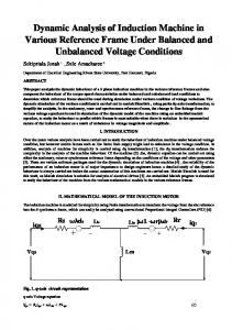
The block diagram of the simulation model developed is illustrated in Fig. 1. A brief description of the equations involved will be presented in the next sub-sections. GENERAL PROCESS DESCRIPTION The present analysis does not, at the moment, include predictions of exhaust gas emissions and on the other Air T1
p1 Pressure Ratio, p2/p1
1.80
Compressor
1.60
1.40
1.20
1.00 0.1
T2
NTC
Compressor Torque
+ Rack Position
40
0 1240
1280
1320
1360
1400
Fuel Pump Injected Fuel Quantity (mgr/cycle/cyl)
Governor 80
200.0
T4
Turbine Torque
0.0 0
20
40
60
80
Fuel Pump Rack Position (%)
100
SoI
T5
N
τL
p4 min
Diesel Engine
mfi
120.0
40.0
0.5
Inlet Manifold
160.0
80.0
0.4
p3
pg
120
0.3
Intercooler T3
T/C Inertia
0.2
Mass Flow Rate, V/ (T/293) 1/2 (m3 /s)
p2
τD
60
-
τS
50
τe + Engine
40
30
20
10
0 0
90
180
p5 mex
N
270
360
φ
pg
& Load Inertia
-
τfr
Friction model
N Exhaust Manifold p6 T6 Turbine p7 T7 Exhaust
Fig.1. Block diagram of the developed simulation code
N
ratio Ф is also taken into account through the following correction equation for the activation constant ‘act’,
act = act o ⋅ (∆Φ Φo )c
The last term on the right hand side of Eq. (4b) takes into account the crank’s angular acceleration ‘ε’ in the piston acceleration.
(1)
with the subscript ‘o’ denoting reference conditions. The improved model of Annand [24] is used to simulate heat loss QL to the cylinder walls,
⎧⎪ k g ⎫ ⎡ dQL a′ dTg ⎤ 4 4 ⎪ =A ⎨ Reb ⎢a(Tg − Tw ) + ⎥ + c(Tg − Tw )⎬ (2) dt ω dt ⎦ ⎣ ⎩⎪ D ⎭⎪ where a, a’, b and c are constants evaluated after experimental matching at steady-state conditions, A=2Apist+A', with Apist=(πD2/4) the piston cross section area, A'=πDx, with x the instantaneous cylinder height in contact with the gas (see Eq. (3) below). Further, k g is the gas thermal conductivity, and the Reynolds number Re is calculated with a characteristic speed derived from a k-ε turbulence model and a characteristic length equal to the piston diameter. During transient operation, the thermal inertia of the cylinder wall is taken into account, using a detailed heat transfer scheme that models the temperature distribution from the gas to the cylinder wall up to the coolant (convection from gas to internal wall surface and from external wall surface to coolant, and conduction across the cylinder wall).
Fig. 2. Schematic diagram of slider crank mechanism identifying the various forces developed
BEARINGS LOADING At each instant of time, the piston displacement from the top dead center (TDC) position is determined by [8]
(
x( ϕ) = r(1 − cos ϕ) + Lrod 1 − 1 − λ 2 sin2 ϕ
)
(3)
where r is the crank radius, λ=r/Lrod with Lrod the connecting rod length (see also Fig. 2), and the crank angle φ is measured from the TDC position. Differentiating the above equation with respect to time, we get the instantaneous piston velocity ⎛ ⎞ λ cos ϕ ⎟ upist (ϕ) = ωr sin ϕ ⎜ 1 + ⎜ 1 − λ 2 sin2 ϕ ⎟⎠ ⎝
The loading of the bearings can then be computed from the following equations, with reference to Fig. 3 [25,26] B0x = −mrod.l ⋅ b sin β B0y = −
B1x = −mrod.r ⋅ upist ⋅ ω ⋅ cos β B1y =
F(ϕ) − mrod.r ⋅ rω2 cos(ϕ + β) cos β
(6)
(4a)
⎛ cos 2ϕ + λ sin ϕ 1 upist ⎞ b(ϕ) = ω2r ⎜ cos ϕ + λ + ε ⎟ ⎜ (1 − λ 2 sin2 ϕ)3 / 2 ω2 rω ⎟⎠ (4b) ⎝ 4
(5)
for the connecting rod small end bearing,
for the connecting rod big end bearing,
while differentiating once again with respect to time, we get the instantaneous piston acceleration 2
F(ϕ) − mrod.l ⋅ b cos β cos β
B2x = B2y = − for the crank pin,
F(ϕ) sin(ϕ + β) cos β
F(ϕ) cos(ϕ + β) + mrod.r ⋅ rω2 cos β
(7)
Y X Y
m rod. l b
B0
Frod β θ0
X φ
Connecting Rod Small End Bearing
Fig. 3. Force distribution for bearing loadings evaluation
B3x = −
F(ϕ) sin(ϕ + β) cos β
⎡ F(ϕ) ⎤ B3y = ⎢ cos(ϕ + β) − (mrod.r + mcrank ) ⋅ rω2 ⎥ cos β ⎣ ⎦
(8)
for the crank journal1, and B 4x = − ⎡F(ϕ) tan β + (mrod.r + mcrank ) ⋅ rω2 sin ϕ ⎤ ⎣ ⎦ 2 B4y = ⎡ −F(ϕ) + (mrod.r + mcrank ) ⋅ rω cos ϕ ⎤ ⎣ ⎦
(9)
An important aspect of friction theory is the mode of lubrication, which as shown in Fig. 4 can be hydrodynamic, mixed or boundary. In hydrodynamic friction the surfaces are separated by a liquid film, minimizing the respective wear. As the pressure increases or the speed decreases, the oil film thins out to the point where its thickness is comparable in size to the surface irregularities. This is the mixed lubrication regime. With further increase in load or decrease in speed, the boundary layer regime is reached, which, for internal combustion engine applications, is experienced around dead centers, at engine start-up and shut-down modes [28].
for the main crankshaft bearing.
1 Boundary
Bi = Bix2 + Bi2y
(10a)
and the angle θ, shown in Fig. 3, is given by ⎛B θi = tan ⎜ ix ⎜ Biy ⎝ −1
⎞ ⎟ ⎟ ⎠
(10b)
In Eqs (5-9), β corresponds to the connecting rod angle 2
2
(see also Fig. 2), i.e. β = cos [ (1 − λ sin ϕ)] . The total force acting on the piston is composed of the gas and the inertia force, i.e. F(ϕ) = Fg (ϕ) + F( l ϕ) , which then propagates into the thrust force Fthr (ϕ) = F(ϕ) ⋅ tan β and the force in the direction of the connecting rod Frod (ϕ) = F(ϕ) / cos β . The gas force is determined by
Fg (ϕ) = (pg (ϕ) − patm ) ⋅ Apist
while
the
reciprocating
masses (inertia) force by Fl (ϕ) = −ml ⋅ b(ϕ) , with the reciprocating
mass
ml = mrod.l + mpist
FRICTION MODELING For the computation of friction torque, at each degree crank angle, the model proposed by Taraza et al. [21] is adopted, which describes the non-steady profile of friction torque during each cycle. In this model the total amount of friction is divided into four parts, i.e. piston rings assembly (including piston rings and piston skirt contribution), loaded bearings, valve train and auxiliaries. A brief description of the model will be given in the next sub-sections. More details can be found in Refs [21,27,13]. For each bearing force in Eqs (8) and (9), the contribution from both cylinders that surround this journal is taken into account.
Hydrodynamic
Piston Rings 0.1 Valve Train Piston Skirt Bearings 0.01
Duty Parameter, s
Fig. 4. Stribeck diagram of friction coefficients for various internal combustion engine components
Piston rings assembly For most of the piston stroke, lubrication is assumed hydrodynamic, with metal contact occurring near firing TDC. The duty parameter s of the typical Stribeck diagram (see also Fig. 4) is defined by
and
mrod.l = mrod − mrod.r , i.e. the connecting rod is assumed equivalent to two masses, one reciprocating with the piston assembly and the other rotating with the crank.
1
Mixed
0.001
with i = 0…4 according to the bearing studied.
−1
Friction Coefficient, f
The corresponding total bearing force is then
s=
µoil upist Fring / Lring
(11)
with Lring the active length of the ring profile, upist the instantaneous piston velocity from Eq. (4a), and Fring the normal force of the ring profile, which is the sum of the ring diametral elastic tension and the instantaneous force from the gas pressure inside the cylinder. Oil viscosity µoil is approximated by the Vogel equation
µoil = Coil
⎛ Θ1 ⎞ ⎜⎜ Θ +Θ ⎟⎟ ⋅ e⎝ oil 2 ⎠
(12)
where Coil, Θ1 and Θ2 are constants depending on the oil type [29], and Θoil is the mean, over an engine cycle, oil temperature in oC. Increase in oil temperature is generally desirable as it reduces the oil film viscosity,
thus decreasing the amount of friction; however, some researchers have reported an increase in engine wear [9]. For hydrodynamic coefficient is [8,9]
lubrication
(s>scr),
the
fpr = C ⋅ sm
friction
(13a)
whereas, for the mixed lubrication regime (s